1
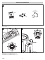
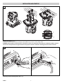
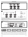
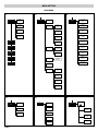
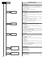
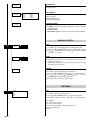
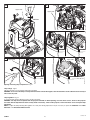
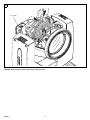
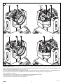
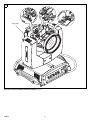
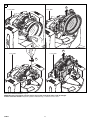
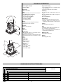
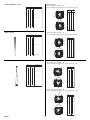
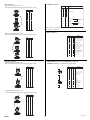
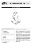
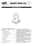
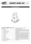
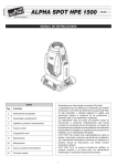
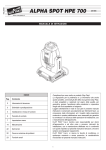
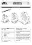
ENGLISH
®
SHARPY
C61375
INSTRUCTION MANUAL
INDEX
Page
Contents
2
Safety information
3
Unpacking and preparation
4
Installation and start-up
5
Control panel
7
Menu setting
14
Maintenance
20
Optional accessories
21
Technical information
21
Cause and solution of problems
22
Channel functions
Congratulations on choosing a Clay Paky product!
We thank you for your custom.
Please note that this product, as all the others in the rich Clay
Paky range, has been designed and made with total quality to
ensure excellent performance and best meet your expectations
and requirements.
Carefully read this instruction manual in its entirety and keep it
safe for future reference. It is essential to know the information
and comply with the instructions given in this manual to ensure
the fitting is installed, used and serviced correctly and safely.
CLAY PAKY S.p.A. disclaims all liability for damage to the fitting
or to other property or persons deriving from installation, use and
maintenance that have not been carried out in conformity with this
instruction manual, which must always accompany the fitting.
CLAY PAKY S.p.A. reserves the right to modify the
characteristics stated in this instruction manual at any time and
without prior notice.
1
SAFETY INFORMATION
• Installation
Make sure all parts for fixing the projector are in a good state of repair.
Make sure the point of anchorage is stable before positioning the projector.
The safety chain must be properly hooked onto the fitting and secured to the framework, so that, if
the primary support system fails, the fitting falls as little as possible.
If the safety chain gets used, it needs to be replaced with a genuine spare.
189W
• MINIMUM DISTANCE OF ILLUMINATED OBJECTS
The projector needs to be positioned so that the objects hit by the beam of light are at least
12 metres (39’4”) from the lens of the projector.
12
• Minimum distance from flammable materials
The projector must be positioned so that any flammable materials are at least 0.20 metres (8") from
every point on the surface of the fitting.
• Mounting surfaces
It is permissible to mount the fitting on normally flammable surfaces.
• Maximum ambient temperature
Do not operate the fixture if the ambient temperature (Ta) exceeds 40° C (104° F).
IP20
• IP20 protection rating
The fitting is protected against penetration by solid bodies of over 12mm (0.47”) in diameter (first
digit 2), but not against dripping water, rain, splashes or jets of water (second digit 0).
• Protection against electrical shock
Connection must be made to a power supply system fitted with efficient earthing (Class I appliance
according to standard EN 60598-1).
It is, moreover, recommended to protect the supply lines of the projectors from indirect contact
and/or shorting to earth by using appropriately sized residual current devices.
• Connection to mains supply
Connection to the electricity mains must be carried out by a qualified electrical installer.
Check that the mains frequency and voltage correspond to those for which the projector is designed
as given on the electrical data label.
This label also gives the input power to which you need to refer to evaluate the maximum number
of fittings to connect to the electricity line, in order to avoid overloading.
tc 100°C
• Temperature of the external surface
The maximum temperature that can be reached on the external surface of the fitting, in a thermally
steady state, is 100°C (212°F).
• Maintenance
Before starting any maintenance work or cleaning the projector, cut off power from the mains
supply.
After switching off, do not remove any parts of the fitting, to avoid getting burnt for at least 35
minutes. After this time the likelihood of the lamp exploding is virtually nill.
The fitting is designed to hold in any splinters produced by a lamp exploding. The lenses must be
mounted and, if visibly damaged, they have to be replaced with genuine spares.
• Lamp
The fitting mounts a high-pressure lamp that needs an external igniter. This igniter is fitted onto the
apparatus.
- Carefully read the "operating instructions" provided by the lamp manufacturer.
- Immediately replace the lamp if damaged or deformed by heat.
Pb
• Battery
This product contains a rechargeable lead-acid battery. To preserve the environment, please
dispose the battery at the end of its life according to the regulation in force. Instructions on how to
remove the battery from the product are available on www.claypaky.it
The products referred to in this manual conform to the European Community Directives to which
they are subject:
• Low Voltage 2006/95/CE
• Electromagnetic Compatibility 2004/108/CE
SHARPY
2
UNPACKING AND PREPARATION
1
Lamp 189W
(fitted into projector)
099108
2 x 183102/802
Packing contents - Fig. 1
2
3
PAN Mechanism Lock and Release (every 90°) - Fig. 2
TILT Mechanism Lock and Release (every 45°) - Fig. 3
SHARPY
3
INSTALLATION AND START-UP
4
Installing the projector - Fig. 4
The projector can be installed on the floor resting on special rubber feet, on a truss or on the ceiling or wall.
WARNING: with the exception of when the projector is positioned on the floor, the safety cable must be fitted. (Cod. 105041/003 available on request).
This must be securely fixed to the support structure of the projector and then connected to the fixing point at the centre of the base.
5
1
2
2
3
1
Connecting and disconnecting power cable - Fig. 5
SHARPY
4
CONTROL PANEL
6
Mains
L
N
Connecting to the mains supply - Fig. 6
7
DMX 512
5 PIN
5
4
3
1
2
SCREEN
SIGNAL
SIGNAL
DMX 512
DMX 512
3 PIN
SIGNAL
2
SCREEN
1
3
SIGNAL
Connecting to the control signal line (DMX) - Fig. 7
Use a cable conforming to specifications EIA RS-485: 2-pole twisted, shielded, 120Ohm characteristic impedance, 22-24 AWG, low capacity. Do not use
microphone cable or other cable with characteristics differing from those specified. The end connections must be made using XLR type 3 or 5-pin male/female
connectors. A terminating plug must be inserted into the last projector with a resistance of 120Ohm (minimum 1/4 W) between terminals 2 and 3.
IMPORTANT: The wires must not make contact with each other or with the metal casing of the connectors. The casing itself must be connected to the
shield braid and to pin 1 of the connectors.
8
Fixture ID
2
Dmx Address
1
Warning Message
12m
Switching on the projector - Fig. 8
Press the switch. The projector starts resetting the effects. At the same time, the following information scrolls on the display:
Model
SHARPY
Firmware
Version X.X.X
Date - Hour
xxx (Fixture ID)
Dmx Address xxx
System errors
E: .........................
W: .........................
On conclusion of resetting in case of absence of the dmx signal, Pan and Tilt move to the “Home” position (Pan 50% - Tilt 50%). The control panel
(Fig. 8) has a display and buttons for the complete programming and management of the projector menu. The display can be in one of two
conditions: rest status and setting status. When it is in the rest status, the display shows the projector’s DMX address and the Fixture ID address
(if set).
During menu setting status, after a wait time (about 30 seconds) without any key having been pressed, the display automatically returns to rest status.
It should be noted than when this condition occurs, any possible value that has been modified but not yet confirmed with the
key will be cancelled.
F
Continue
SHARPY
5
➔
9
28
28
Reversal of the display - Fig. 9
To activate this function, press UP
and DOWN
keys simultaneously while the display is in the rest mode. This status will be memorised and
maintained even for the next time it will be switched on. To return to the initial state, repeat the operation all over again.
Setting the projector starting address
On each projector, the starting address must be set for the control signal (addresses from 1 to 512).
The address can also be set with the projector switched off.
Setting the address: see pag. 8.
Setting the projector Fixture ID
On each projector, the Fixture ID address must be set for an easy identification of the fixtures in an installation (ID from 1 to 255).
The Fixture ID address can be set with the projector switched off.
Setting the Fixture ID: see pag. 8.
B
C
Functions of the buttons - Using the menu
F
C
DOWN
Confirms the displayed value, or activates the displayed function, or enters the successive
menu.
Decreases the value displayed (with auto-repetitions) or passes to the next item in the menu.
B
Increases the value displayed (with auto-repetitions) or passes to the previous item in a menu.
D
Return to the top level
E
Commute from units, tens, hundreds, in the "Address", "Fixture ID" and "Calibration" menù.
UP
LEFT
RIGHT
USING THE MENU:
1) Press
once – “Main Menu” appears on the display.
2) Use the UP
and DOWN
keys to select the menu to be used:
• Setup (Setup Menu): To set the setting options.
• Option (Option Menu): To set the operating options
• Informations (Informations Menu): To read the counters, software version and other information.
• Manual Control (Manual control Menu): To trigger the test and manual control functions.
• Test (Test Menu): To check the proper functionning of effects
• Advanced (Advanced Menu): Access to the "Advanced menu" is recommended for a trained technical personnel.
To enable the "Advanced" see pag.13
3) Press
to display the first item in the selected menu.
4) Use the UP
and DOWN
keys to select the MENU items.
F
F
B
C
B
C
Setting addresses and options with the projector disconnected
The projector’s DMX address, as well as other possible operating options, can also be set when the appliance is disconnected from the electricity supply.
All that is needed is to press
to momentarily activate the display and thus access the settings. Once the required operations have been carried out,
the display will switch off again after a wait time of 30 seconds.
F
SHARPY
6
MENU SETTING
MAIN MENU
1
2
Set Up
Dmx
Address
3
Option
Channel
Mode
Information
Lamp Dmx
Pan / Tilt
Fixture ID
Ethernet
Interface
Invert
Pan
Fixture
Hours
Invert
Tilt
Lamp
Hours
Lamp
Strikes
Swap
Pan-Tilt
Option
System
Version
Encoder
Pan-Tilt
Information
Color
Manual
Control
Board
Diagnostic
Fixed Wheel
Shortcut
Dmx
Monitor
Linear
Movement
Test
Shutter
Fans
Monitor
Shutter
On Error
Network
parameters
Advanced
Display
Setting
System
Errors
Default
Preset
User
Preset 1
User
Preset 2
User
Preset 3
4
5
Manual
Control
Lamp
Reset
Channel
6
Test
Pan / Tilt
Colour
Advanced
Access code
1234
Upload
Firmware
Beam
Gobo
Setup
Model
Calibration
All
Continue
SHARPY
7
➔
NOTE: On grey the default options
Set Up
Dmx
Address
SET UP MENU
DMX ADDRESS
NOTE: without the DMX signal the Address (XXX) flashing
Allows you to select the DMX ADDRESS.
1) Press
- the current DMX Adress appear on the display.
2) Use the UP
and DOWN
, RIGHT
keys to plan the DMX
Address.
3) Press
to confirm the selection or LEFT
to keep current settings.
Address xxx
F
B
C
E
D
F
Channel
Mode
CHANNEL MODE
Allows you to select a channel arrangement from the two available.
1) Press
- the current settings appear on the display (Standard or
Vector).
2) Use the UP
and DOWN
keys to select one of the following
settings:
- Standard
- Vector
3) Press
to confirm the selection or LEFT
to keep current settings.
Standard
F
Vector
B
C
F
Fixture ID
D
FIXTURE ID
Allows you to select the FIXTURE ID.
- the current Fixture ID appear on the display.
1) Press
2) Use the UP
, DOWN
, RIGHT
keys to plan the Fixture ID.
3) Press
to confirm the selection or LEFT
to keep current settings.
Value xxx
F
B
F
C
E
ETHERNET INTERFACE
It lets you set the Ethernet settings to be attributed to the projector.
1) Premere
.
2) Use the UP
and DOWN
keys to select the “Ethernet Interface”
options to set:
Ethernet
Interface
F
B
C
Control Protocol
It lets you select the “Control Protocol” Art-net to assign according to the
control unit used:
1) Press
the current setting appears on the display.
2) Use the UP
and DOWN
keys to select one of the following settings:
- Disabled
- Art-net on IP 2
- Art-net on IP 10
3) Press
to confirm the selection or LEFT
to keep the current setting.
Control
Protocol
F
B
C
F
D
Repeat on DMX
It lets you enable the transmission of the Ethernet protocol by DMX signal
to all the connected projectors.
1) Press
the current setting appears on the display.
2) Use the UP
and DOWN
keys to select one of the following settings:
- Disabled: DMX transmission disabled.
- Enabled on primary: DMX transmission enabled.
3) Press
to confirm the selection or LEFT
to keep the current setting.
Repeat on
DMX
F
B
C
F
D
Universe
It lets you assign the “Universe” number to be assigned to a series of
projectors.
1) Press
– the current Universe address appears on the display.
2) Use the UP
, DOWN
, RIGHT
keys to set the Universe address.
3) Press
to confirm the selection or LEFT
to keep the current setting.
Universe
F
B
F
SHARPY
D
8
C
E
D
OPTIONS MENU
LAMP DMX
Used for enabling lamp remote control channel.
1) Press
- the current settings appear on the display (On or Off).
2) Use the UP
and DOWN
keys to enable (On) or disable (Off)
the lamp remote control channel.
3) Press
to confirm the selection or LEFT
to keep current settings.
On
Option
Lamp Dmx
Off
F
B
C
F
Pan / Tilt
Invert
Pan
D
PAN / TILT
Invert pan
Used for reversing Pan movement.
1) Press
- the current settings appear on the display (On or Off).
2) Use the UP
and DOWN
keys to enable (On) or disable (Off)
PAN inversion.
3) Press
to confirm the selection or LEFT
to keep current settings.
On
Off
F
B
C
F
Invert
Tilt
D
Invert tilt
Used for reversing tilt movement.
1) Press
- the current settings appear on the display (On or Off).
2) Use the UP
and DOWN
keys to enable (On) or disable (Off)
Tilt inversion.
to confirm the selection or LEFT
to keep current settings.
3) Press
On
Off
F
B
C
F
Swap
Pan-Tilt
D
Swap Pan-Tilt
Used for swapping Pan and Tilt channels (as well as Pan fine and Tilt fine).
1) Press
- the current settings appear on the display (On or Off).
2) Use the UP
and DOWN
keys to enable (On) or disable (Off)
Pan and Tilt channel swap.
3) Press
to confirm the selection or LEFT
to keep current settings.
On
Off
F
B
C
F
Encoder
Pan-Tilt
D
Encoder Pan-Tilt
Used for enabling the Pan / Tilt encoders.
1) Press
- the current settings appear on the display (On or Off).
2) Use the UP
and DOWN
keys to enable (On) or disable (Off)
Pan / Tilt encoders.
3) Press
to confirm the selection or LEFT
to keep current settings.
On
Off
F
B
C
F
Color
Fixwheel
Shortcut
D
COLOR
Fixed wheel short-cut
Used for optimizing color change time so that the disc turns in the direction that requires shorter movement.
1) Press
– the current settings appear on the display (On or Off).
2) Use the UP
and DOWN
keys to enable (On) or disable (Off)
color change optimization.
3) Press
to confirm the selection, or LEFT
to keep current settings.
On
Off
F
B
C
F
Linear
Movement
D
Linear Movement
It enables the linear movement of the colour wheel.
1) Press
– the current settings appear on the display (On or Off).
2) Use the UP
and DOWN
keys to enable (On) or disable (Off)
the linear movement of the colour wheel.
3) Press
to confirm the selection, or LEFT
to keep current settings.
On
Off
F
F
B
C
D
Continue
SHARPY
9
➔
Shutter
Shutter
On Error
SHUTTER
Shutter on error
Used for automatically closing the stop/strobe in the event of Pan/Tilt
position error.
1) Press
- the current settings appear on the display (On or Off).
2) Use the UP
and DOWN
keys to enable (On) or disable (Off)
automatic stop/strobe closing in the event of Pan/Tilt position error.
3) Press
to confirm the selection, or LEFT
to keep current settings.
On
Off
F
B
C
F
D
DISPLAY
Used for automatically reduce brightness on the display after about 30
seconds in idle.
1) Press
- the current settings appear on the display (On or Off).
2) Use the UP
and DOWN
keys to enable (On) or disable (Off) the
decreasing of display brightness.
3) Press
to confirm the selection or LEFT
to keep current settings.
On
Display
Off
F
B
C
F
Setting
Default
Preset
SETTING
Used to save 3 different settings of the items in the options menu and
relative submenus.
1) Press
- “Default preset” appears on the display.
2) Use the UP
and DOWN
keys to select one of the following
configurations:
- Default preset (*)
- User preset 1
- User preset 2
- User Preset 3
3) Press
- “Load preset X” appears on the display.
4) Use the UP
and DOWN
keys to select:
- Load preset X to recall a previously stored configuration.
- Save to preset X to store the current configuration.
a confirmation message (Are you sure?) appears on the display.
5) Select YES to confirm the selection or NO to keep the current setting
and return to the next higher level.
Reset To
Dafault
Go Back
User
Preset 1
F
Load
Preset 1
Save To
Preset 1
User
Preset 2
Load
Preset 2
F
Save To
Preset 2
User
Preset 3
Load
Preset 3
Save To
Preset 3
B
C
B
C
(*) DEFAULT PRESET
Used for restoring default values on all options menu items and relevant submenus.
1) Press
, a confirmation message (Are you sure?) appears on the display.
2) Select YES to confirm the selction or NO to keep current setting.
OPTION
DEFAULT
Lamp DMX
On
Invert Pan
Off
Invert Tilt
Off
Swap Pan-Tilt
Off
Encoder Pan-Tilt
On
Fixed Wheel Shortcut
On
Shutter on error
Off
Display
On
F
SHARPY
D
10
Information
System
Errors
INFORMATION MENU
SYSTEM ERRORS
Shows a list of warnings and messages relevant to errors occurred since
the fixtures switching-on.
1) Pressing
you are allowed to reset the SYSTEM ERRORS list.
A confirmation message (Are you sure you want to clear error list ?)
appears on the display.
2) Select YES to reset the list or NO to go back.
F
Fixture
Hours
FIXTURE HOURS
Used for displaying projector operating hours (total and partial).
1) Press
- Hours total and partial appears on the display.
Total counter
Counts the number of projector working life hours (from manufacture to
date).
Partial counter
Counts the number of partial projector working life hours since the
last reset to date.
2) Press
to reset partial projector working hours a confirmation
message (Are you sure?) appears on the display.
3) Select YES to reset partial projectors counter or NO to keep the
current setting and return to the top menu level.
Total XXX
Partial XXX
Reset...
F
F
Lamp
Hours
LAMP HOURS
Used for displaying the lamp working hours (total and partial).
1) Press
- Hours total and partial appears on the display.
Total counter
Counts the number of projector working hours with the lamp on (from
manufacture to date).
Partial counter
Counts the number of lamp working hours since the last reset to date.
2) Press
to reset partial lamp working hours, a confirmation message
(Are you sure ?) appears on the display.
3) Select YES to reset partial counter or NO to keep the current setting
and return to the top menu level
Total XXX
Partial XXX
F
Reset...
F
Lamp
Strikes
LAMP STRIKES
Used for displaying the number of times the lamp was turned on (total and
partial).
1) Press
- the number of times the lamp was turned on (total and
partial) appears on the display.
Total counter
Counts the number of times the lamp was turned on (from manufacture
to date).
Partial counter
Counts the number of times the lamp was turned on since the last
reset to date.
2) Press
to reset partial lamp strikes hours, a confirmation message
(Are you sure ?) appears on the display.
3) Select YES to reset partial counter or NO to keep the current setting
and return to the top menu level
Total XXX
Partial XXX
Reset...
F
F
System
Version
Board
CPU brd
com.dev
0: PT-3f
1: 8-Ch
Revis.
x.x.x
x.x
x.x
x.x
Hw.rv.
x.x
x.x
x.x
SYSTEM VERSION
Used for displaying the software and hardware version of each board
installed in the projector.
CPU brd (CPU board)
0: PT-3f (Pan / Tilt board)
1: 8-Ch (8 channel board)
Board
Diagnost.
Board
0:PT-3f
1:8-Ch
Status
Good
Good
Err%
0.00
0.00
BOARD DIAGNOSTIC
Used for displaying the status error of each board installed in the projector:
0: PT-3f (Pan / Tilt board)
1: 8-Ch (8 channel board)
Continue
SHARPY
11
➔
DMX MONITOR
Used for displaying the projector DMX channel level in bit (Val) and in
percentage (Perc).
Dmx
Monitor
Fans
Monitor
Fan
Lamp
Lamp
BallIn
PwrSp
FANS MONITOR
Used for displaying the speed of each fan installed in the projector:
Lamp (Lamp Fan)
Ball. IN (Ballast IN Fan)
PwrSp (Power Supply Fan)
Speed (RPM)
XXXX
XXXX
XXXX
XXXX
NETWORK PARAMS
Allows the "Network" parameters of the projector to be displayed or:
IP address: Internet Protocol address (two projectors must not have the
same IP address)
IP mask: 255.0.0.0
Mac address: Media Access Control: the projector’s Ethernet Address
Network
params
MANUAL CONTROL
Manual
Control
LAMP
Used for turning lamp on and off from the projector control panel.
- the current settings appear on the display (On or Off).
1) Press
2) Use the UP
and DOWN
keys to turn the lamp on (On) or off (Off)
3) Press
to confirm the selection or LEFT
to keep current settings
and return to the top level.
On
Lamp
F
B
F
Off
C
D
RESET
Used for resetting the projector.
1) Press
to reset the projectors, a confirmation message (Are you sure
?) appears on the display.
2) Select YES to starting reset the fixture or NO to keep the current setting
and return to the top menu level.
No
Reset
Yes
F
CHANNEL
Used for setting channel levels from the projector control panel.
1) Press
- the first channel appears on the display.
2) Use the UP
and DOWN
keys to select the required channel:
3) Press
and use the UP
and DOWN
keys to select the
required DMX level (value between 0 and 255).
4) Press LEFT
to return to the top menu level.
Channel
F
B
F
D
C
B
C
TEST MENU
Test
TEST
Allows you to check the proper functioning of effects.
1) Press
to return to the top menu level.
2) Use the UP
and DOWN
keys to select the required test.
3) Press
to confirm the selection or LEFT
to keep current settings.
Pan-Tilt
Colour
Beam
Gobo
All
F
B
F
C
D
Test sequence:
Pan - Tilt effects (Pan & Tilt)
Colour effects (Colour wheel)
Beam effects (Stopper-Strobe / Dimmer / Prism / Frost)
Gobo effects (Static gobo)
All effects
SHARPY
12
ADVANCED MENU
Advanced
To enable the "Advanced Menu" set up the "Access code" (1234) using the
UP
, DOWN
, RIGHT
keys.
Press
- "Menu advanced" appears on the display
Code
1234
B
F
C
E
Upload
Firmware
Transfer the firmware on all
the connected fixtures ?
Are you sure ?
Yes/No
UP LOAD FIRMWARE
Allows you to transfer the firmware from 1 fixture to all the connected fixtures.
1) Press
, a confirmation message appears on the display.
2) Select YES to start the firmware loading or NO to keep the current setting and return to the top menu level
Setup
Model
Changing to a wrong model
may damage the fixture.
Are you sure ?
Yes/No
SETUP MODEL
Allows you to change the default model of projector.
1) Press
a confirmation message appears on the display.
2) Select YES to define the model of projector or NO to keep the current
setting and return to the top menu level.
F
F
CALIBRATION
Allows you to adjust effects from the control panel to obtain perfect uniformity between the projectors.
1) Press
- “channels” appears on the display.
2) Using the UP
and DOWN
keys, select the effect you wish to
regulate.
and use the RIGHT
, UP
and DOWN
buttons to
3) Press
make the adjustment by setting a value between 0 and 255.
4) Press
to confirm the selection or LEFT
to keep current settings and return to the top level.
Calibration
F
F
F
B
C
E
B
C
D
FACTORY DEFAULT
Allows you to restore default values of all channels (128).
1) Press
– a confirmation message appears on the display (Reset
calibration to factory default ?).
2) Select YES to reset calibration to factory default or NO to keep the
current setting and return to the top menu level.
F
SHARPY
13
MAINTENANCE
10
11
2
1
1
1/4 Turn
2
1/4 Turn
3
4
Locking and releasing Pan and Tilt movements - Refer to the instructions in the UNPACKING AND PREPARATION section.
Opening the head covers - Fig. 10.
Closing the head covers - Fig. 11.
SHARPY
14
13
12
1
Upper Side
Upper Side
2
1
2
1/4 Turn
Upper Side
Upper Side
4
3
14
5
Upper Side
Upper Side
6
Opening and closing lamp compartment - Fig. 12
Lamp change - Fig 13
Take the new lamp out of its package and insert in the fitting.
WARNING: do not touch the lamp’s envelope with bare hands. Should this happen, clean the bulb with a cloth soaked in alcohol and dry it
with a clean, dry cloth.
Lamp regulation - Fig. 14
To centre the lamp, turn the adjusting screw as shown in the figure.
WARNING: The lamp must be adjusted with the projector switched off. After adjusting, close the effects covers, switch on the projector
and check that the adjustment has been correctly made. If necessary, switch off the projector, remove the effects covers and repeat lamp
adjustment.
NOTE: To adjust the lamp vertically (with regard to the Y axis) after having replaced it, it may be necessary to operate the Calibration in the Menu
Advanced on the Fixed Gobo Wheel channel.
Continue
SHARPY
15
➔
15
2
Lower Side
1
Replacing fixed gobos wheel - Fig. 15
WARNING: Before using personalised gobos wheel contact Clay Paky.
SHARPY
16
16
Lower Side
Lower Side
Upper Side
Upper Side
Periodical cleaning - Fig. 16
To ensure optimal operation and performance for a long time it is essential to periodically clean the parts subject to dust and grease deposits. The
frequency with which the following operations are to be carried out depends on various factors, such as the amount of the effects and the quality of the
working environment (air humidity, presence of dust, salinity, etc.).
Use a soft cloth dampened with any detergent liquid for cleaning glass to remove the dirt from the reflectors and filters. It is recommended that the
projector undergoes an annual service by a qualified technician for special maintenance involving at least the following operations:
• General cleaning of internal parts.
• Restoring lubrication of all parts subject to friction, using lubricants specifically supplied by Clay Paky.
• General visual check of the internal components, cabling, mechanical parts, etc.
• Electrical, photometric and functional checks; eventual repairs.
Continue
SHARPY
17
➔
17
1
2
3
Upper Side
Extraction of the effect modules: Preliminary operations - Fig. 17
SHARPY
18
18
2
Lower Side
Lower Side
1
4
Lower Side
Lower Side
3
Extraction of the effect modules - Fig. 18
IMPORTANT: Grasp the modules using the support structure and not the details which could get damaged.
Insertion of the effect modules: Repeat the operations indicated in Fig. 17 and 18 in reverse order.
SHARPY
19
OPTIONAL ACCESSORIES
19
Lower Side
1
2
C61190
Heat screen filter - Fig. 19
An optional filter kit is also available when the SHARPY projector is used in environments that do not meet the minimum allowed distance of 12
metres from illuminated objects; when this kit is assembled, the projector can be used at a minimum distance of 8 metres from illuminated objects.
20
Lower Side
1
2
C61190 accessory can be placed inside the projector when not in use - Fig. 20
SHARPY
20
TECHNICAL INFORMATION
IP20 protection rating:
• Protected against the entry of solid bodies larger
than 12mm (0.47”).
• No protection against the entry of liquids.
Power supplies available
115/230V 50/60Hz
Input power:
350VA a 230V 50Hz.
Lamp:
Lamp system with a short arc burner in a reflector
• Type MSD Platinum 5R (L10103)
- Output Lamp power: 189W
- Colour temperature 8000 K
- Luminous flux 7950lm
- Average life 2000 h
- Any working position
315
(12.40")
280
(11.02")
Motors:
13 stepper motors, operating with microsteps,
totally microprocessor controlled.
Movable body:
• Movement by means of two stepper motors,
controlled by microprocessor.
• Automatic repositioning of PAN and TILT after
accidental movement not controlled by control
unit.
• Travel:
- PAN = 540°
- TILT = 252°
• Maximum speeds:
- PAN = 2.45 sec
- TILT = 1.30 sec
• Resolution:
- PAN = 2.11°
- PAN FINE = 0.008°
- TILT = 0.98°
- TILT FINE = 0.004°
345
(13.58")
475
(18.70")
330
(12.99")
Body:
• Aluminium structure with die-cast plastic cover.
• Two side handles for transportation.
• Device locking PAN and TILT mechanisms for
transportation and maintenance.
Inputs:
• DMX 512
185
(7.28")
Safety Devices:
• Bipolar circuit breaker with thermal protection.
• Automatic break in power supply in case of
overheating or failed operation of cooling system.
Cooling:
Forced ventilation with axial fans.
Channels:
Max 20 control channels.
450
(17.72")
CE Marking:
In conformity with the European Union Low
Voltage
Directive 2006/95/CE and Electromagnetic
compatibility
Directive 2004/108/CE.
Working position
Functioning in any position.
Weights:
about 16 Kg (35lbs 3ozs).
405
(15.94")
CAUSE AND SOLUTION OF PROBLEMS
THE PROJECTOR WILL NOT SWITCH ON
ELECTRONICS NON-OPERATIONAL
PROBLEMS
DEFECTIVE PROJECTION
REDUCED LUMINOSITY
POSSIBLE CAUSES
No mains supply.
Lamp exhausted or defective.
Signal transmission cable faulty or disconnected.
Incorrect addressing.
Fault in the electronic circuits.
Lenses or reflector broken
Dust or grease deposited.
SHARPY
CHECKS AND REMEDIES
Check the power supply voltage.
Replace the lamp. (See instructions).
Replace the cables.
Check addresses (see instructions).
Call an authorised technician.
Call an authorised technician.
Clean (see instructions).
21
CHANNEL FUNCTION
SHARPY
CHANNEL MODE
CHANNEL
STANDARD
VECTOR
1
COLOUR WHEEL
COLOUR WHEEL
2
STOP / STROBE
STOP / STROBE
3
DIMMER
DIMMER
4
STATIC GOBO CHANGE
STATIC GOBO CHANGE
5
PRISM INSERTION
PRISM INSERTION
6
PRISM ROTATION
PRISM ROTATION
7
EFFECTS MOVEMENT
EFFECTS MOVEMENT
8
FROST
FROST
9
FOCUS
FOCUS
10
PAN
PAN
11
PAN FINE
PAN FINE
12
TILT
TILT
13
TILT FINE
TILT FINE
14
FUNCTION
FUNCTION
15
RESET
RESET
16
LAMP CONTROL (with Option "Lamp Dmx" ON)
LAMP CONTROL (with Option "Lamp Dmx" ON)
17
PAN - TILT TIME
18
COLOUR TIME
19
BEAM TIME
20
GOBO TIME
SHARPY
22
NOTE: On conclusion of resetting in case of absence of DMX signal, Pan & Tilt move to the "Home" position (Pan 50% - Tilt 50%) all the others channels stay at 0%.
• COLOUR WHEEL - channel 1
• STATIC GOBO CHANGE - channel 4
%
255
100
50.0
48.7
47.0
45.5
43.7
42.0
40.5
38.7
36.7
35.0
33.7
32.0
30.0
28.7
27.0
25.0
23.7
22.0
20.5
18.2
16.7
15.0
13.7
11.7
10.0
8.7
7.0
5.0
3.7
2.0
0.0
128
124
120
116
111
107
103
99
94
90
86
82
77
73
69
64
60
56
52
47
43
39
35
30
26
22
18
13
9
5
0
EFFECT
FAST ROTATION (160 rpm)
MACRO
BIT
SLOW ROTATION (0.2 rpm)
BLUE + WHITE
BLUE
CTB 8000 + BLUE
CTB 8000
CTO 190 + CTB 8000
CTO 190
CTO 260 + CTO 190
CTO 260
CYAN + CTO 260
CYAN
MAGENTA + CYAN
MAGENTA
YELLOW + MAGENTA
YELLOW
PINK + YELLOW
PINK
LAVENDER + PINK
LAVENDER
LIGHT GREEN + LAVENDER
LIGHT GREEN
GREEN + LIGHT GREEN
GREEN
AQUAMARINE + GREEN
AQUAMARINE
ORANGE + AQUAMARINE
ORANGE
RED + ORANGE
RED
WHITE + RED
WHITE
10
9
8
7
11
12
• STOP / STROBE - channel 2
6
13
5
14
4
3
15
2
16
17
MACRO
WHITE
BIT
%
EFFECT
252 - 255
239 - 251
226 - 238
213 - 225
208 - 212
207
98.7 - 100
93.7 - 98.2
88.7 - 93.2
83.7 - 88.2
81.7 - 83.2
81.2
OPEN
RANDOM FAST STROBE
RANDOM MEDIUM STROBE
RANDOM SLOW STROBE
OPEN
FAST PULSATION (360 bpm)
1
BIT
%
EFFECT
255
100
GOBO 16 SHAKE FAST SPEED (600 bpm)
250
249
98.0
97.5
GOBO 16 SHAKE, SLOW SPEED (24 bpm)
GOBO 15 SHAKE FAST SPEED
244
243
95.5
95.0
GOBO 15 SHAKE, SLOW SPEED
GOBO 14 SHAKE FAST SPEED
237
236
93.0
92.5
GOBO 14 SHAKE, SLOW SPEED
GOBO 13 SHAKE FAST SPEED
231
230
90.5
90.0
GOBO 13 SHAKE, SLOW SPEED
GOBO 12 SHAKE FAST SPEED
224
223
88.0
87.5
GOBO 12 SHAKE, SLOW SPEED
GOBO 11 SHAKE FAST SPEED
218
217
85.5
85.0
GOBO 11 SHAKE, SLOW SPEED
GOBO 10 SHAKE FAST SPEED
212
211
83.2
83.0
GOBO 10 SHAKE, SLOW SPEED
GOBO 9 SHAKE FAST SPEED
205
204
80.5
80.0
GOBO 9 SHAKE, SLOW SPEED
GOBO 8 SHAKE FAST SPEED
199
198
78.0
77.5
GOBO 8 SHAKE, SLOW SPEED
GOBO 7 SHAKE FAST SPEED
192
191
75.0
74.7
GOBO 7 SHAKE, SLOW SPEED
GOBO 6 SHAKE FAST SPEED
186
185
73.0
72.5
GOBO 6 SHAKE, SLOW SPEED
GOBO 5 SHAKE FAST SPEED
180
179
70.5
70.0
GOBO 5 SHAKE, SLOW SPEED
GOBO 4 SHAKE FAST SPEED
173
172
68.0
67.5
GOBO 4 SHAKE, SLOW SPEED
GOBO 3 SHAKE FAST SPEED
167
166
65.5
65.0
GOBO 3 SHAKE, SLOW SPEED
GOBO 2 SHAKE FAST SPEED
160
63.0
GOBO 2 SHAKE, SLOW SPEED
159
62.5
FAST ROTATION (60 rpm)
SLOW ROTATION (5 rpm)
118
46.2
114-117
44.7-46.0
113
44.2
SLOW ROTATION (5 rpm)
72
28.2
FAST ROTATION (60 rpm)
68-71
64-67
60-63
56-59
52-55
48-51
44-47
40-43
36-39
32-35
28-31
24-27
20-23
16-19
12-15
8-11
4-7
0-3
26.7-28.0
25.0-26.2
23.7-24.7
22.0-23.2
20.5-21.7
18.7-20.0
17.0-18.2
15.5-16.7
14.0-15.0
12.5-13.7
11.0-12.0
9.5-10.5
8.0-9.0
6.2-7.5
4.7-6.0
3.2-4.2
1.7–3.0
0.0–1.2
STOP
GOBO 17
GOBO 16
GOBO 15
GOBO 14
GOBO 13
GOBO 12
GOBO 11
GOBO 10
GOBO 9
GOBO 8
GOBO 7
GOBO 6
GOBO 5
GOBO 4
GOBO 3
GOBO 2
GOBO 1
WHITE
• PRISM INSERTION - channel 5
BIT
%
255
100
EFFECT
PRISM INSERTED
0%-100%: 0.36 sec
108
104 - 107
103
42.5
41.0 - 42.0
40.5
SLOW PULSATION (30 bpm)
OPEN
FAST STROBE (12 flash/sec)
128
127
4
0-3
1.7
0.0 - 1.2
50.0
49.7
PRISM EXCLUDED
SLOW STROBE (1 flash/sec)
CLOSED
0
0.0
• DIMMER - channel 3
• PRISM ROTATION - channel 6
BIT
%
255
100
EFFECT
0%-100%: 0.02 sec
540°
360°
0°
0.0
%
EFFECT
255
100
FAST ROTATION (43 rpm)
193
75.5
SLOW ROTATION (1.1 rph)
191 - 192 74.7 - 75.0 STOP
190
74.2
SLOW ROTATION (1.1 rph)
STOP
0
BIT
128
127
50.0
49.7
FAST ROTATION (43 rpm)
POSITION 540°
105
41.7
POSITION 450°
84
33.0
POSITION 360°
63
24.7
POSITION 270°
42
16.2
POSITION 180°
21
8.2
POSITION 90°
0
0.0
POSITION 0°
Continue
SHARPY
23
➔
• EFFECTS MOVEMENT - channel 7
BIT
%
255
100
• PAN - channel 10
Operation with option InvertPan Off
(Tilt conventionally represented at 14% and option Invert Tilt
G
EFFECT
GOff)
BIT
%
255
100
0
0.0
0%-100%: 0.33 sec
0
0.0
• FROST - channel 8
G
Operation with option InvertPan On
(Tilt conventionally represented at 14% and option Invert Tilt
BIT
%
255
100
EFFECT
GOff)
FROST INSERTED
BIT
%
255
100
0
0.0
0%-100%: 0.12 sec
0
0.0
FROST EXCLUDED
• FOCUS - channel 9
• PAN FINE - channel 11
Operation with option InvertPan Off
(Tilt conventionally represented at 14% and option Invert Tilt
G
BIT
%
255
100
EFFECT
GOff)
NEAR
BIT
%
255
100
0
0.0
0%-100%: 1.11 sec
0
0.0
DISTANT
G
Operation with option InvertPan On
(Tilt conventionally represented at 14% and option Invert Tilt
SHARPY
24
GOff)
BIT
%
255
100
0
0.0
• TILT - channel 12
Operation with option Invert Tilt Off
(Pan conventionally represented at 0% and option Invert Pan
G
SE
BIT
%
255
100
• FUNCTION - channel: 14
GOff)
BIT
%
255
100
EFFECT
UNUSED RANGE
L
TX
D
X
E
63
128
51-62
20.0-24.2 LINEAR (Default)
38-50
14.7-19.5 CONVENTIONAL
DIMMER CURVE
FUNCTION
50.0
SEL
TX
D
24.7
X
E
0
25-37
9.7-14.2 NORMAL
12-24
4.7-9.5
FAST (Default)
0-11
0.0-4.2
UNUSED RANGE
PAN-TILT
FUNCTION
The functions are actived passing through the unused range and staying 5
seconds in necessary level.
0.0
SEL
TX
D
X
E
• RESET - channel: 15
G
Operation with option Invert Tilt On
(Pan conventionally represented at 0% and option Invert Pan
BIT
%
255
100
GOff)
BIT
%
EFFECT
255
100
COMPLETE RESET
Complete reset is activated passing
throug the unused range and staying
5 seconds in complete reset levels.
SEL
TX
DMX
S
E
128
127
50.0
49.7
COMPLETE RESET
PAN / TILT RESET
Pan / Tilt reset is activated passing
throug the unused range and staying
5 seconds in Pan / Tilt reset levels.
128
50.0
77
76
S EL
TX
DMX
S
30.0
29.7
PAN / TILT RESET
EFFECTS RESET
E
Effects reset is activated passing
throug the unused range and staying
5 seconds in Effects reset levels.
26
25
10.0
9.7
0
0.0
EFFECTS RESET
UNUSED RANGE
0
0.0
SEL
TX
DMX
S
E
• TILT FINE - channel 13
Operation with option Invert Tilt Off
(Pan conventionally represented at 0% and option Invert Pan
G
BIT
%
255
100
• LAMP CONTROL (only with option LAMP DMX On) - channel: 16
GOff)
IMPORTANT: SHARPY is not provided with hot restrike ignition
BIT
%
255
100
EFFECT
LAMP ON
ON
Lamp switch-on passing
through the unused range
and staying 5 sec
in Lamp ON levels.
SEL
TX
DMX
S
E
ON
OFF
101
100
39.5
39.0
LAMP ON
LAMP OFF
Lamp switch off passing
throug the unused
range and staying 5 s in
Lamp OFF levels.
OFF
0
SEL
0.0
TX
DMX
S
E
G
Operation with option Invert Tilt On
(Pan conventionally represented at 0% and option Invert Pan
SE
BIT
%
255
100
0
0.0
26
25
10.0
9.7
0
0.0
LAMP OFF
UNUSED RANGE
GOff)
L
TX
DM
X
S
E
S
E
SEL
TX
DMX
Continue
SHARPY
25
➔
TIMING CHANNELS
Timing Channel
Channel function
17
Pan - Tilt time
Pan - Tilt - (Pan fine - Tilt fine)
18
Colour time
Colour wheel
19
Beam time
Dimmer - Frost - Prism
20
Gobo time
Static Gobo
TIME TABLE
BIT
0
1
2
3
4
5
6
7
8
9
10
11
12
13
14
15
16
17
18
19
20
21
22
23
24
25
26
27
28
29
30
31
32
33
34
35
36
37
38
39
40
41
42
SHARPY
Seconds
Full
0.2
0.4
0.6
0.8
1
1.2
1.4
1.6
1.8
2
2.2
2.4
2.6
2.8
3
3.2
3.4
3.6
3.8
4
4.2
4.4
4.6
4.8
5
5.2
5.4
5.6
5.8
6
6.2
6.4
6.6
6.8
7
7.2
7.4
7.6
7.8
8
8.2
8.4
BIT
43
44
45
46
47
48
49
50
51
52
53
54
55
56
57
58
59
60
61
62
63
64
65
66
67
68
69
70
71
72
73
74
75
76
77
78
79
80
81
82
83
84
85
Seconds
8.6
8.8
9
9.2
9.4
9.6
9.8
10
10.2
10.4
10.6
11
12
13
14
15
16
17
18
19
20
21
22
23
BIT
86
87
88
89
90
91
92
93
94
95
96
97
98
99
100
101
102
103
104
105
106
107
108
109
110
111
112
113
114
115
116
117
118
119
120
121
122
123
124
125
126
127
128
Seconds
BIT
129
130
131
132
133
134
135
136
137
138
139
140
141
142
143
144
145
146
147
148
149
150
151
152
153
154
155
156
157
158
159
160
161
162
163
164
165
166
167
168
169
170
171
24
25
26
27
28
29
30
31
32
33
34
35
36
37
38
39
40
26
Seconds
41
42
43
44
45
46
47
48
49
50
51
52
53
54
55
56
57
BIT
172
173
174
175
176
177
178
179
180
181
182
183
184
185
186
187
188
189
190
191
192
193
194
195
196
197
198
199
200
201
202
203
204
205
206
207
208
209
210
211
212
213
214
215
Seconds
58
59
60
65
70
75
80
85
90
95
100
110
120
130
140
150
BIT
216
217
218
219
220
221
222
223
224
225
226
227
228
229
230
231
232
233
234
235
236
237
238
239
240
241
242
243
244
245
246
247
248
249
250
251
252
253
254
255
160
Seconds
170
180
190
200
210
220
230
240
250
260
270
280
290
300
310
Follow cue
Data
gfstudio.com
Cod. 099108-EN
Rev. 1 05/12
CLAY PAKY S.p.A. - Via Pastrengo, 3/b - 24068 Seriate (BG) Italy - Tel. +39-035-654311 - Fax +39-035-301876 - www.claypaky.it