1
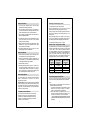
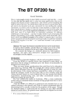
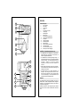
ENGLISH Parts Description 1 1. 2. 3. 4. 5. 6. 7. 8. 9. 10. 11. 12. 13. 14. 15. 16. 17. 18. 2 3 4 5 6 Zoom Indicator Zoom Head Fresnel Lens Sensor Decorative Front Panel Locking Ring Mounting Base Battery Cover Ready indicator (orange LED) Flash On/Off and Mode Switch Hold Button Tilting Angle Scale Swivel Angle Scale Distance Table Detection Indicator (green LED) Power Ratio Switch Power-On indicator (red LED) Bracket (not shown in diagram) CAUTION Read this section before use § The DF200 flash unit is designed to be used with any digital camera with a built-in flash. The DF200 can be used as a supplemental slave flash. § The DF200 flash unit contains high voltage circuitry. To avoid electrical shock or burn, do not attempt to dismantle any part of the flash. If the external shell of the flash unit is broken or cracked, do not touch the internal mechanisms or circuitry even when the batteries are removed. 13 § When replacing the batteries, replace all of the battery cells. With weaker cells, the flash unit will take longer to recharge for the next shot. 14 § The DF200 flash unit is neither weatherproof nor waterproof. When using the DF200 in the rain or near water, avoid any contact with water. The warranty does not cover water damage. It is often impractical to repair electrical components damaged by water. 7 12 8 15 9 Batteries 16 10 11 17 The DF200 flash unit uses four AA batteries. You may use alkaline, NiCD, or NiMH rechargeable batteries. Manganese batteries are not recommended, because of shorter life and longer flash recharging time. Replace the batteries if the Orange Ready LED Indicator take s more than 30 seconds to illuminate after each flash shot. 1 Battery Precautions Attaching and Removing the Flash 1. To ensure proper electrical contact, clean the battery terminals before installing the batteries. Turn the Flash On/Off (10) to the Off position. 2. To prevent battery explosion, leakage or overheating, use four new AA batteries of the same type and brand. Do not mix and match different types or new/used batteries. 3. Do not attempt to recharge batteries other than NiCD or NiMH rechargeable batteries. 4. If the flash will not be used for an extended period of time, remove all batteries from the flash to avoid possible damage from battery leakage. 5. Battery performance decreases at low temperatures. Keep batteries warm (near room temperature) before using them, especially in cold weather. 6. Take spare batteries when going on a long trip, or when photographing outdoors in cold weather. Battery Installation 1. Turn the Flash On/Off Switch (10) to the Off position, then open the Battery Cover (8) by sliding it forward. 2. Insert four AA batteries into the battery compartment. Be sure the polarity (+,-) of the batteries are aligned according to the diagram inside the battery chamber. 3. Close the Battery Cover (8). 4. Slide the Flash On/Off Switch (10) to the “1” position. The red Power-On Indicator (17) will light come on. You may hear the high-pitch whine of the capacitor as it charges. After a few seconds, the orange Ready Indicator (9) will light up indicating that the flash is ready for use. Auto Standby System To conserve battery power, the flash unit will automatically switch to standby mode if the flash is not used for approximately 3 minutes. Important Note : Even though the flash unit is automatically switched to standby mode, it will still use some battery power for flash detection. Therefore, if the flash will not be used for a long period, it is recommended that you set the Flash On/Off Switch (10) to the Off position. Low-Battery Power Indication The amount of time that it takes for the orange Ready Indicator LED to come on is your indication of battery condition. As the batteries are depleted, the time will increase. As the charge time approaches 30 seconds, consider a new set of batteries. 2 Slide the Mounting Base (7) onto the shoe on the flash bracket and turn the Locking Ring (6) until it is secure. When you attach or remove the flash, grasp the bottom of the flash to prevent damage to the Mounting Base (7) or the bracket’s shoe. Mount your digital camera on the bracket, on the grip pad, using the ¼-20 thumbscrew and tighten securely. (Refer to the following section “Flash Photography with the DF200”.) Turn the Flash On/Off Switch to the “1” position. Distance Table – Using the Zoom Head The distance table (14) on the back of the flash suggests the maximum effective flash range for the five (5) zoom positions - W2, W1, MID, T1 and T2 . The zoom positions correlate to the “35mm equivalence” focal length of your digital camera lens. (Digital cameras vary greatly. Use these numbers as a guide.) In general: use W1, W2 for wide angle, MID for normal (no zoom), and T1, T2 for telephoto. Select the zoom setting appropriate for your lens positioning. For example : Guide Number (in meters) 23 25 28 30 31 Zoom range of camera (35mm equivalence) 28-34mm 35-49mm 50-84mm 85-104mm 105mm and above Suggested Zoom Position on flash unit (in mm) W2 W1 MID T1 T2 *This table is based on Full power setting - Power setting 1 (W2 = 28mm, W1 = 35mm, MID = 50mm, T1 = 85mm, T2 = 105mm) Flash Photography with the DF200 In order to ensure that the images taken with your digital camera are sufficiently illuminated, follow these instructions: Step: 1. Before mounting your digital camera onto the bracket set the White Balance and Flash mode: i. If your digital camera allows for the adjustment of white balance, set the camera to “sunlight”, or “outdoors”. (*Refer to your digital camera user manual.) ii. Set the flash mode of your digital camera to “On“ or “Red Eye” to ensure that the flash is emitted for every shot. “On” is also known as “fill” for some cameras. 0 For most digital cameras “Red Eye Reduction” mode will pre-pulse the camera flash several times prior to the actual flash pulse. 3 2. Once you have set the white balance and flash mode on your digital camera you may mount your camera onto the flash bracket. 3. Turn on your digital camera and take a few shots using the camera’s built-in flash. If you can, count the number of flash pulses emitted by your camera’s built-in flash each time it flashes. (Many digital cameras emit more than one pulse.) Hold (Manual Standby) Feature The DF200 is a slave flash, triggered by your cameras built-in flash. In a situation where other cameras are present it is possible that your DF200 flash may be triggered by another cameras flash. You may prevent this by using the DF200’s hold feature. Press the hold button (11) to suspend the operation of the DF200 temporarily. 4. Look at the DF200 Flash On/Off and Mode Switch (10). § If your digital camera flash emits only one pulse - slide the DF200 On/Off and Mode Switch (10) to the “1” position. Proceed to Step 6 . § If your digital camera flash emits two pulses - slide the DF200 On/Off and Mode Switch (10) to the “2/N ” position. Proceed to Step 6. § If you cannot determine the number of pulses emitted by your camera’s built-in flash proceed to Step 5 for further instructions to profile your flash. 5. If the number of flash pulses cannot be determined: i. Slide the Flash On/Off and Mode Switch (10) to the “DETECT” position. ii. Take a flash shot with your digital camera. (Make sure the digital camera flash fires.) iii. Shortly after the camera flash has fired, the green “detect” LED indicator (15) should illuminate for approximately two seconds indicating that the DF200 has “learned” the flash profile of this digital camera. If the green detect indicator LED does not light up, switch off the DF200 and repeat the prior two -step procedure. iv. After the DF200 has successfully detected your digital camera’s flash, slide the DF200 switch (10) from “DETECT” to “2/N”. (One detent position to the left.) v. The DF200 has now “profiled” your digital camera flash and is now synchronized with it. Try a few sample shots. Important note: If the DF200 flash is switched off it will “forget” the profile for your camera. Turn on the DF200 and repeat the profiling procedure (step V). To use your DF200 with a different digital camera, turn the DF200 off and repeat the profiling procedure, if necessary. 6. Next, adjust the zoom position of the DF200 flash head to match the field of view of your digital camera. Refer to the Distance Table (14) as a guide. If your digital camera does not have an optical zoom lens, try the MID position. 7. Next, set the DF 200 power level. Depending on the lighting conditions and distance to your subject, the power of the DF200 can be set to four different power ratios: 1 (full), 1/4 th, 1/8 th, or 1/16 th power. Based upon the zoom setting and distance to your subject, use the distance table to select a suitable power level. Take a few shots to perfect your settings. 8. Now, you are ready for digital flash photography. When the hold button (11) is depressed, the green detect indicator LED (15) will illuminate, indicating that your DF200 is now temporarily inactive. While on hold, the green LED will remain a steady green. The DF200 will not respond to any flash trigger, either intentional or not. 4 5 To resume operation, depress the hold button (11) again and the green detection indicator (15) will cease to illuminate. The DF200 is now ready to resume normal operation. Power Output (Power Ratio Switch) The flash output can be adjusted manually to prevent under or over-exposure. The power of the DF200 flash can be set adjusting the “Power Ratio” switch to four intensities: 1 (Full power), 1/4, 1/8, or 1/16 power. Use this table as a guide: ft/meter Power Setting ZOOM 1 1/4 1/8 1/16 W2 75/23 37/11 26/8 18/5 W1 83/25 41/13 30/9 20/6 MID 92/28 46/14 33/10 23/7 T1 98/30 49/15 35/11 24/7 T2 102/31 51/16 36/11 25/8 Bounce Flash When you take a flash photograph, sometimes a strong shadow will appear behind the subject as a result of a direct flash. To minimize or eliminate this shado w, tilt the flash head upward to reflect the flash off of the ceiling or a wall. The flash head is adjustable from 0° to 90° vertically. There are detents (click-stops) at several positions including 30°, 45°, 60 °, 75 ° and 90° positions. The flash head may be rotated 330° horizontally for additional flexibility. § The effectiveness of a bounce flash is dependent upon distance and the condition of the reflecting surface. The angle of the flash must be set properly to achieve the best possible lighting effect. Normally, when a flash is bounced against a surface, it loses 2-3 apertures of light (f-stops), even if the surface is white. § Exposure in bounce lighting is a factor based upon distance, first from the flash to the reflected surface, then to the subject and finally back to the camera. The exposure will vary with camera aperture setting, the distances involved, and quality of the reflective surface. Experiment to derive the best results. § The use of a white surface is highly recommended for bounce lighting effects, resultant in the best overall reflective light level. If a colored surface is used for bounce lighting, it will reflect its color upon the subject. Specifications Guide number 28 @ISO 100 Power Settings Four Power Ratios: Full, 1/4 th, 1/8 th, 1/16 th Zoom Range Five detent positions: W2, W1, MID, T1, T2 Bounce Angle 0° - 90° (multiple detents) Swivel Angle 330 ° (multiple detents) Ready Light Orange LED Detect Light Green LED Ready Light Red LED Auto Power Standby Three minutes Duration of Flash Max. 1/1000 second Note Power Source We are continually upgrading the DF200 flash to meet market demands. As such, specifications may change and the product may vary slightly from the description provided in this manual. Check the Vivitar website for updates and information at www.vivitar.com 4 AA batteries (Alkaline, NiCd, or NiMH Recommended) Number of Flashes - Alkaline - NiCd or NiMH Approximate flashes/battery set 80 – 1000 150 – 2000 Recycling Time - Alkaline - NiCd or NiMH 0.5 – 8 seconds 0.5 – 7 seconds Color Temperature 5,600k Weight (w/o batteries) 240 grams Dimension (mm) 70.0 (L) x 175.0 (H) x 45 (W) Compatibility All digital cameras with built in flash Precautions During Use 1. The DF200 is a precision instrument. Be very careful not to bump or drop it. 2. Avoid exposure to extremely high or low temperatures or excessive humidity. Store your flash away from heat or direct sunlight. Never store in a car. Always use fresh batteries, and replace all 4 batteries du ring replacement. 3. Do not use a thinner, benzene or other cleaning agents to remove dirt or fingerprints from the unit. Clean with a soft, moistened cloth. 4. When the flash unit is brought from a cold exterior into a warm interior, condensation may occur on the inside of the flash unit. In such case, do not use the flash unit until it has reached room temperature. 5. For extended storage, choose a cool dry place, preferably with good ventilation. Never store the flash in a drawer or cupboard containing naphthalene or camphor (moth balls) as these will have negative effects on the flash. 6 7