1
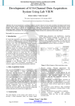
Modal Testing Excitation Guidelines
Marco A. Peres and Richard W. Bono, The Modal Shop, Inc., Cincinnati, Ohio
Electrodynamic shakers or exciters are commonly used in
experimental modal analysis. The practical aspects regarding
the setup of the shakers, stingers and transducers are often the
source of test difficulties and avoidable measurement errors.
This article reviews the basics of shakers as beneficial to modal
testing and common problems associated with setup issues and
resulting measurement errors. These include shaker alignment,
sensor considerations, stinger selection, amplifiers, reciprocity
assumptions and other test-related circumstances.
A system setup for modal testing includes several measurement and test components around the structure under test itself.
Typically one or more electrodynamic shakers (also called modal
exciters) are employed to provide a known excitation input force to
the structure. Dynamic transducers are used to measure the input
excitation force and the resulting vibration responses. Once data
are acquired, the resulting frequency response functions (FRFs)
obtained by the data acquisition system are stored for post processing calculations, data reduction, curve fitting, and mode extraction.
Figure 1 offers a simple representation of the main instrumentation
components found in a modal test setup.
Multichannel dynamic signal analyzers (DSAs) are required to
acquire data. Many of today’s DSAs have 24-bit A/D (analog to
digital) converters with built-in signal conditioning (ICP® or IEPE
inputs) and built-in source channels (signal generator) to drive the
shaker system and provide mechanical excitation to the structure.
Advanced modal software incorporates robust geometry-driven
data acquisition wizards, analysis methods and algorithms. What
was extremely difficult or almost an art many years ago, has been
greatly simplified for easier and faster modal testing.
In addition to all the recent advancements on the analysis side,
new methods and algorithms for modal parameter extractions, the
challenges of acquiring good data for experimental modal analysis
are still very real. The old adage “garbage in, garbage out” becomes
more present than ever if care and attention are not paid to some
of the basic practical aspects behind test setups. And as another
old saying goes, a chain is no stronger than its weakest link. So in
a forced input modal test system, special attention must be paid to
the excitation setup to ensure good quality data and representative
results, especially considering that it is the reference measurement used in the processing of FRFs. Accordingly, it is critical to
understand the practical aspects of shaker setup for modal testing
measurements with respect to the force sensor, the modal exciter
and the power amplifier.
Obtaining Valid Measurements
Sensor Selection. Piezoelectric force sensors and piezoelectric
impedance heads are the two most common transducers used for
measuring input forces. An impedance head is nothing more than
a transducer that measures both force and resulting driving point
response in one device. Today, an impedance head is typically an
accelerometer and force transducer built together, but it was originally based on a velocity transducer and force transducer. (This
is where the name impedance head comes from and has lingered
on today even though velocity is not normally measured.) This is
a critical measurement in experimental modal analysis, and it is
recommended that impedance heads be used in most cases. A combination of a separate force transducer and accelerometer mounted
next to each other is often used instead, but the convenience and
accuracy of measuring the driving point excitation with a single
transducer and validating reciprocity between input locations is
best obtained with an impedance head.1
A force transducer with sensitivities in the range of 11 to 22
Based on SAE paper 2011-01-1652 presented at the 2011 Noise and Vibration Conference, Grand Rapids, MI, May 2011. Copyright © 2011 SAE
International.
8 SOUND & VIBRATION/NOVEMBER 2011
Figure 1. Typical modal test setup.
Figure 2. Force transducer (shown installed on modal stinger).
mV/N (50 to 100 mV/lbf) allows forces up to ±445 N (±100 lbf)
to be measured; typically more than enough force range for most
modal application scenarios. Also available are impedance head
transducers with TEDS (transducer electronic data sheet) capability
as described by the IEEE 1451.4 standard.2 The built-in memory
available on TEDS transducers stores sensor calibration information
and specifications allowing plug-and-play functionality when the
sensor is connected to the data acquisition system. This simplifies
system setup and minimizes chances of human error due to entering incorrect sensitivity values when setting up the channels.
Sensor Mounting Considerations. A very important consideration when mounting force transducers is recognizing that the
typical force transducers used are “uni-directional.” This means
two things: first, that force transducers are designed to accurately
measure force on only one of its two mounting faces, for example
labeled “top” and “base” as seen on Figure 2. This is due to the
fact that the force transducer itself has mass and stiffness. They
are designed and calibrated to read force accurately on one of its
mounting faces so they need to be installed accordingly.
Note that, for this model force transducer, the “top” of the unit
is the designed sensing surface and should be mounted directly to
the test article. Some impedance head transducers have an indication of exactly which side to mount to the structure. In any case,
it is always a good idea to refer to the transducer’s user manual
for identifying which mounting surface is intended to measure
the force accurately.
Secondly, because the sensor measures force in only one direction, a stinger is used to reduce any possible side loads that may be
transmitted. Note that this piezoelectric force sensor is mounted to
a thin rod-style stinger that is stiff in the axial direction and flexible
in the lateral direction. (This is detailed later in this article.)
Another important consideration is that the force transducer
should always be mounted directly to the test structure, between
it and the stinger and shaker assembly. If the force gage is mounted
on the exciter side, as shown in the illustration in Figure 3, then
the dynamics of the stinger become part of the measured function.
(This is generally only an issue when using a conventional shaker
for modal applications; modal shakers, as we will see later, have
www.SandV.com
Figure 5. Section view of generic electrodynamic shaker.
Figure 3. Typical stinger setup showing proper force transducer location relative to test article, threaded stinger rod, and exciter. Left configuration shows
correct way of mounting force sensor next to structure (force gage “divorces”
the stinger/shaker from the structure) as opposed to mounting the sensor on
shaker/exciter side, where the stinger becomes part of test structure.
Figure 6. Electromagnetic force equation of conductor immersed in magnetic
field; F = electromagnetic force, L = length of conductor, I = current vector,
B = magnetic field vector.
Figure 4. Impedance head mounted in skewed orientation to test structure.
a through-hole armature design and would not allow the force
transducer to be mounted incorrectly).
The force transducer is usually mounted using a threaded adhesive mounting base (Figure 4) firmly attached to the test structure
using dental cement, two-part quick epoxy, or a cyanoacrylate type
adhesive (Super Glue or Loctite®). Often a piece of foil adhesive
tape is first applied to protect the surface of the test article, with the
mounting pad bonded to the tape. Dental cement is ideal because it
is extremely stiff, providing rigid attachment within the frequency
range of typical modal testing. If the test structure can be drilled
and tapped with an appropriate thread, directly attaching the force
transducer to the structure is the best solution.
Electrodynamic Shakers
Principle of Operation. A shaker (or exciter) is an electrodynamic
transducer consisting of a voice coil attached to a moving armature,
and a magnet structure with a small gap in which the voice coil
moves (see Figures 5 and 6). The magnet structure is designed to
provide a strong magnetic field across the gap, so when the current flows in the voice coil it will experience a force dependent on
the strength of the current and the magnetic field. Small shakers
www.SandV.com
(with sine peak force capability below 500 N or 100 lbf) – or most
modal shakers in the market today – typically use high-strength
permanent magnets. Larger shakers use electromagnets instead
(field coils). An alternating electric current in the voice coil causes
the shaker to move forward and backwards in the magnetic field,
causing the armature and the test article to vibrate accordingly to
a certain input signal.
Several different magnet systems have been used in electrodynamic exciters. They typically consist of a cast magnet of a special
magnetic alloy or a ceramic material. In general the greater the magnetic flux, the greater the efficiency of the shaker. Al-Ni-Co magnets
(an alloy of aluminum, nickel, and cobalt) became available in the
early 1930s and have been used in electrodynamic shakers until
the 1980s. In the mid ’80s rare-earth magnets became available,
and almost all modern shaker designs benefit from neodymium
magnets (based on an alloy of the rare earth metal neodymium,
iron, and boron).
These magnets are about four times stronger than Al-Ni-Co
magnets for a given size, which offers a great benefit for shaker
performance and usability. Modern shakers can deliver forces
more efficiently and can be constructed much lighter than previously. Shaker manufacturers have been able to achieve up to a
67% reduction in weight, enabling truly “one-man” handling for
the exciter.
In summary, new lightweight shakers are easier to handle and
fixture during installation, especially when the test engineer needs
to move the shaker around and try different excitation points. This
is very common in large-channel-count modal tests.
Shaker Quantity and Force Requirements. The question on how
many shakers are required by a certain modal test is often hard
to answer. Often test systems are limited by the total number of
output sources in the data acquisition system or shakers available
SOUND & VIBRATION/NOVEMBER 2011 9
in the test lab for modal testing. Usually two to four shakers are
sufficient for most tests, particularly when testing larger structures
like automobiles or aircraft. Generally, tests with more than five
shakers are rare. Ultimately, there need to be enough shakers acting as reference locations that are positioned so that the modes of
interest of the structure are adequately excited and observed, and
good frequency response measurements are obtained. This includes
having multiple shaker/reference locations to resolve repeated roots
and/or closely spaced modes.
The excitation levels for modal testing are usually reasonably
low. There is no need to provide large force levels for conducting
a modal test especially if appropriate response transducers (accelerometers) are selected with good sensitivity and resolution,
as well as high quality, high resolution (24-bit technology is fairly
standard in today’s commercial offerings) data acquisition systems.
The level only needs to be sufficient enough to make good measurements. In fact, larger force levels tend to overdrive the structure,
exciting nonlinear characteristics of the structure and providing
poorer overall measurements than with lower level force tests. For
this reason, again, on larger structures, it is often desirable to use
multiple shakers at lower force levels to more evenly distribute
force than a few single shakers operating at high level forces.
Through-Hole Armature Design. Conventional vibration testing uses a shaker with a traditional mounting platform or table
design; the test article is directly attached to the top surface of the
armature with some base excitation applied, usually monitored
by controlling some prescribed acceleration. The device under
test (DUT) is normally subjected to some operating environment,
generic spectrum or some excessive environment to determine if
the equipment is suitable for the intended service.
In the early days of modal testing with shaker excitation, smaller
shakers were used to apply some low-level excitation to be able to
measure a frequency response function. Usually the shaker was
attached with a long rod, commonly referred to as a stinger or quill,
to impart force to the structure. (The purpose of the stinger was to
dynamically decouple the shaker from the structure.)
Because these traditional shakers were typically used for base
excitation, the armature attachment configuration was not optimal.
Usually, some type of left-right thread arrangement was made or
some type of collar was designed to enable an easier attachment
to the shaker. It was a rather difficult arrangement no matter how
the connection was made, given a threaded interface on both attachment ends. In addition, there had to be some thought given to
shaker position and actual length of stinger needed. If a different
length stinger was needed, then the shaker needed to be reoriented
and realigned, or different stinger lengths were used for the modal
test. Overall, the setup of the traditional shaker for a modal test
was very difficult and cumbersome.
Due to all these problems, specific design configurations better suited for modal testing applications were developed. In the
late 1980s, ideas from the University of Cincinnati’s Structural
Dynamics Research Laboratory gave rise to the through-hole armature with a chuck-and-collet design (like gripping a drill bit on
a hand drill) that enabled very easy adjustment and attachment of
the shaker to the modal test article as shown in Figure 7. A long
stinger can slide into the shaker’s through-hole armature, threaded
to the force transducer attached to the test article, be properly
aligned, and then clamped down with the chuck and collet at the
appropriate length.
These components are shown as an exploded view in Figure 8,
and a video demonstrating actual installment is available on the
Internet.3 This design also easily accommodates stingers of different lengths if needed, and the arrangement is so simple that it is
difficult to imagine having to set up the test without this important
feature. Through-hole armature design with a chuck-and-collet
stinger attachment makes test setup so much easier that the term
modal shaker usually refers specifically to a shaker that comes with
a through-hole armature (as opposed to a traditional platform/table
shaker style used for general vibration testing).
Shaker Mounting and Alignment. Proper force excitation
requires the thrust axis of the modal shaker to be aligned with
the force sensor (or impedance head) mounted on the structure
10 SOUND & VIBRATION/NOVEMBER 2011
Figure 7. Cut-away view of through-hole armature shaker design.
under test. Failure to do so may
result in unmeasured forces
transmitted to the structure
due to the side loading of the
sensor and possible mechanical or electrical shaker damage
due to forcing and rubbing of
the armature coil. Alignment
issues cause difficulty in any
modal test. Care must be taken
to provide the best alignment
possible to attain the best possible measurements.
Modal shakers can be bolted
to the floor or any suitable base
by using the holes located in the
base of the shaker trunnion. By
loosening the trunnion body,
the modal shaker’s angular position can be adjusted by rotating
it in the trunnion base. Ergonomic handles are included in
some shakers (Figure 7 and 10)
to facilitate the task of tightening/loosening the trunnion and
rotating the shaker. Often it is
helpful to run a bead of temporary adhesive, such as hot glue,
around the edge of the trunnion
to secure the shaker during
testing. This will help to avoid
“creep” during testing, which
Figure 8. Exploded view of chuck- could cause further misalignand-collet stinger attachment on ment and measurement errors.
modal shaker with through-hole
One way to align the shakarmature design (A-force sensor or
impedance head, B-stinger, C-chuck er during setup is to use the
top piece, D-collet, E-chuck bottom stinger. In setting up a shaker
piece, F-armature, G-modal exciter.
test, typically the stinger is slid
into the shaker’s through-hole armature with the force transducer
or impedance head attached to the end of the stinger. With the
shaker collet loosened, the stinger can be extended in and out of
the armature to obtain the desired length. Once this is done, the
force gage or impedance head mounting pad can be affixed to the
structure as explained previously.
If the alignment is correct, the shaker stinger will easily unthread from the force transducer or impedance head and also
thread right back in without any binding or difficulty whatsoever.
This should be accomplished without the stinger putting side
load onto the shaker armature, sliding easily within the chuckand-collet assembly, which assures that the shaker and stinger
are properly aligned.
At times there may be a threaded mating hole in the structure
www.SandV.com
Figure 9. Lateral shaker stand.
for mounting the force gage or impedance head and attaching
the shaker. Alignment in these situations is much more difficult,
requiring that the shaker or test article be moved so that the fixed
threaded hole places the stinger exactly in the correct position. The
main point is that the shaker must be aligned so that the stinger
can be very easily threaded into the force gage or impedance head
with no difficulty or binding.
If the excitation point on the structure requires suspending
the shaker, an appropriate fixture needs to be employed. Figure
9 shows a typical shaker mounting installation used to laterally
excite an automobile for a modal test of a body-in-white car frame.
The stand allows for coarse adjustment of the shaker’s vertical and
longitudinal positions. A set of four turnbuckles used to hang the
shaker to the stand allows for fine adjustment of the shaker position
and alignment angle to the structure driving point.
Depending on the size or height of the test article, the shaker
stand shown in Figure 9 may be too small, and some special fixture
to hold the shaker needs to be used. It is not uncommon for the
special test fixture to be validated first and checked for its natural
modes of vibration, which may interfere during the actual test of
the article.
In a suspended configuration at very low frequencies below 5-10
Hz, the inertia provided by the shaker body may not be sufficient,
and the shaker may exceed its stroke limits way before it exceeds
its force capability. To minimize this issue, often heavy metal block
masses are attached (bolted) to the base of the shaker trunnion to
enhance performance, providing more (double or triple) inertia to
push against the structure.
Stingers
Theory of Operation. As mentioned earlier, a stinger is always
used on the interface between the shaker and the structure. The
primary reason for the use of an exciter stinger is to prevent lateral
constraint forces and moments.4 By design, an exciter applies axial
force to the test article with high fidelity. Its armature is designed to
not have the freedom to move in a lateral direction, perpendicular
to the force axis. The test article, on the other hand, may have lateral
motion at the forcing point. This may be due to the geometry of the
test article or due to a lateral mode of vibration. This is especially
true if the test article has a soft suspension.
If one were to connect the exciter directly to the forcing point,
the exciter will constrain the article’s tendency to move laterally.
This resistance, even if it is only a small effect, can cause two
www.SandV.com
problems. The first is that the force transducer will have a lateral
force and moment that will not be measured accurately, since it
senses properly only along its principal axis. The second is that
the article feels the combined effect of the intended axial force
and the unintended lateral force and moment. As a result, the
test article would be excited with forces that are not measured at
all. These effects will show up as errors in the force or frequency
response measurements.
An exciter stinger has a lateral (bending) stiffness that is much
smaller than its axial (compression or tension) stiffness. This
means that when the exciter’s armature is stationary, a small
lateral movement of the test article causes a small lateral force at
the exciter, while a small movement in the axial direction causes
a much larger axial force. In other words, axial forces through the
stinger are accompanied by little relative axial motion, but lateral
forces are accompanied by much larger relative lateral motion. The
lateral force and moment generated by lateral motion of the test
article are therefore reduced.
An additional advantage of using a stinger is that a flexible
stinger is more forgiving with positioning and aligning the exciter
at the forcing point. Without a stinger, you may need to have the
mounting centers of the exciter and force transducer within 0.5
mm (0.02 inch) or closer, to get a good bolted connection. This is
difficult to do if you have to move the entire exciter and its support. A stinger can tolerate a misalignment of nearly 10 times this
amount, especially if the stinger is long. This reduces your setup
time. Furthermore, the use of a coupling nut makes attachment and
removal easy compared with other connection methods.
Another advantage of a stinger is the isolation of the test article
from the exciter. If a catastrophe should occur, either by failure of
the test suspension or by a transient voltage into the power amplifier, a large force would be created at the connection between
exciter and test article. The stinger acts as a mechanical fuse as the
weakest link absorbing the damage. As a result, the inexpensive
stinger is sacrificed to save the much more expensive exciter and
test article.
Piano Wire Stinger. Of course the shaker’s dynamic subsystem
will never be perfectly decoupled, and there will practically
always be some slight cross-axis force input to the structure. As
discussed earlier, the intent of the stinger design is to be very stiff
in the axial direction and extremely compliant to lateral loads to
minimize this situation. Piano wire stingers are an excellent way
to circumvent the problems with lateral stiffness associated with
conventional stingers.
The piano wire is pretensioned with a load that is greater than
the alternating load to be applied; a preload of three to four times
the range is considered reasonable. The piano wire is fed through
the core of the through-hole shaker armature, so it is critical to have
a modal shaker that is designed to accommodate this. A simple
preload can be applied with weights or an elastic tie-down strap
(Figure 9). With the preload applied, the collet is used to clamp the
tensioned piano wire. As long as the applied load during shaker
excitation is less that the preload, then the piano wire is an excellent way to transmit force and conduct a modal test, eliminating
the effects of lateral stiffness in conventional stingers. If the applied
load during shaker excitation is more than the preload, it will cause
the wire to buckle and the shaker won’t be able to pass the force to
the structure. This is analogous to an AC signal riding on a DC bias
(or offset), with the equivalent of a mechanical clipping occurring
when the AC signal is greater than the DC offset.
An alternative to the piano wire is a thin rod stinger design (see
Figures 2 and 4), which also utilizes the through-hole armature
design available on modal shakers. Since this design is a stiff rod
(rather than a wire) it does transmit some amount of force laterally.
However, this style of stinger does not need to be pretensioned,
greatly simplifying setup. As a result, it is more commonly used as
an acceptable compromise of performance and ease of use.
The effect of the stinger assembly’s lateral stiffness on the overall
system is very dependent on the stiffness of the structure being
tested. If the structure itself is very stiff, then this is often not a
serious concern. However, when the structure is very flimsy or has
a significant amount of rotational effect at the attachment point of
SOUND & VIBRATION/NOVEMBER 2011 11
Figure 10. Example of 31 N (7 lbf) mini shaker with integrated, 100-W,
Class-D amplifier (bottom).
the stinger, then these lateral loads can become very important and
a source of large measurement error. In addition, these rotational
effects generally become more important at higher frequencies, so
it is always difficult to determine that actual impact on the overall
results. One easy way to determine the stinger lateral and rotational
effects is to make several test runs with the length of the stinger
varying by ±10% and observe the change in the measured drive
point frequency response. Reference 5 provides a good overview
and comparison on stinger types and effects on measured FRFs.
Shaker Amplifiers
A power amplifier is always needed to provide the necessary
energy to drive the shaker. Many considerations come into play
when selecting the right power amplifier for the shaker. As electrodynamic shakers are usually low-impedance devices, one must
ensure the amplifier selected can indeed drive the shaker to its
desired performance. Compatibility between the shaker and amplifier is fundamental along with other requirements such as broad
frequency range, low-frequency response, power rating, power
efficiency, low harmonic distortion, safety features, interlocks,
etc. Using a power amplifier made or recommended by the shaker
manufacturer is the safe choice; it typically guarantees the performance characteristics of the shaker system (sine or random force
capability), which can only be stated once a shaker and amplifier
pair is selected.
Voltage/Current-Mode Amplifiers. As the shaker armature and
coil move through a magnetic field during normal operation, a
voltage is induced in the circuit called back electromotive force
(or simply back EMF). The voltage associated with the back EMF
is proportional to the shaking velocity and it opposes the current
coming from the amplifier. The back EMF functions as an electrodynamic damping term in the system.
Most power amplifiers operate in voltage mode; that is, the
output voltage is proportional to the input voltage waveform
with some gain set by the user. In addition to voltage mode, some
amplifiers can also operate in current mode, where the amplifier’s
output voltage is adjusted to maintain the required current on the
output (to follow the input signal) regardless of back EMF generated in the system.
Current-mode operation allows measurement of free-decay
damping of the structure (by turning the excitation signal off). With
current amplifiers, the armature of the shaker coil is allowed to
freely float after the excitation is terminated, which is highly desirable for sine-dwell or normal-mode tuning (normal-mode testing).
12 SOUND & VIBRATION/NOVEMBER 2011
Current mode is also preferable for studying nonlinearities, which
is often the case in some aerospace structures. It also minimizes
potential force dropouts at resonances that can compromise signalto-noise ratio of the force excitation measurements.6 Current mode
is typically used with sine and swept sine test signals and rarely
or never used with burst signals.
Voltage-mode amplification is the preferable choice for burstrandom and sine-chirp excitation, which are very widely used in
modal testing with single or multiple shakers. When using burstrandom excitation, the response of the system needs to decay to
zero before the end of the sample interval of the FFT analyzer
time capture to minimize leakage. When the amplifier is set up as
a voltage amplifier, then the back EMF effect (the electromotive
force caused by the vibration motion driving the shaker armature
/coil through the shaker’s magnetic field) provides resistance to
the armature and helps cause the system response to decay more
quickly. This may seem to be inappropriate, because it seems that
the shaker system is then supplying damping to the measurement.
But it’s not an issue as long as the force is measured for the entire
measurement. Then the correct input-output relationship is measured. Note that the force needs to be measured and not the electrical parameters of the amplifier to make the correct measurement.
Linear Versus Switching Amplifiers. Historically, most shaker
power amplifiers were linear type, Class A or Class B. Linear
amplifiers have been superseded by the more efficient designs,
though they remain popular for their simplicity and continue to
be available from most shaker manufacturers. Linear amplifiers’
efficiencies are usually in the 50% to 75% range.
Switching amplifiers (Class D) are the most common type used in
new designs for power amplifiers. Theoretical power efficiency of
Class D amplifiers is 100%. That is to say, all of the power supplied
to it is delivered to the load; none is turned to heat. Real-life practical efficiencies well over 90% are common, allowing the design
to be extremely power efficient, lightweight and compact. Figure
10 is a good example where amplifiers are now being integrated
to some shaker designs. Due to its high efficiency and low heat
dissipation, fans and large heat sinks are very small or simply not
needed (as opposed to the large ones always present on traditional
linear amplifiers).
Conclusions
This article presents some practical guidelines and experiencebased insight to effectively perform a modal test. The review was
presented without the use of any detailed mathematical relationships. Attention to excitation test setup details is critical for the
acquisition of quality frequency response function measurements,
which are fundamental for the modal extraction analysis and
consistent results.
Acknowledgements
The authors would like to acknowledge Professor Peter Avitabile from University of Massachusetts Lowell and Professor
David Brown from University of Cincinnati for their invaluable
support, discussions and contributions to the aspects and topics
reviewed here.
References
1. Merkel, R. C., Gatzwiller, K. B., Brown, D. L., “Important Aspects of Precise
Driving Point FRF Measurements Using a Mechanical Impedance Head
Sensor,” Proceedings of the XVI IMAC Conference, pp. 795-799, Santa
Barbara, CA, February 2-5, 1998.
2.“Registration Authority Tutorials,” IEEE Standard 1451.4, http://stan
dards.ieee.org/develop/regauth/tut/
3.The Modal Shop, “Modal Shaker Setup,” http://www.modalshop.com/
video.asp
4.Zimmerman, R. D., “Exciter Stinger,” Quixote Measurement Dynamics,
Inc., Document 59006, November 1985.
5. Cloutier, D., Avitabile P., Bono, R. W., Peres, M. A., “Shaker/Stinger Effects
On Measured Frequency Response Functions,” Proceedings of the XXVII
IMAC Conference, pp. 197-203,Orlando, FL, February 9-12, 2009.
6. Olsen, N. L., “Using and Understanding Electrodynamic Shakers in Modal
Applications,” Proceedings of the IV IMAC Conference, pp. 1160-1167,
Los Angeles, CA, February 3-6, 1986.
The authors can be reached at: [email protected] and rbono@
modalshop.com.
www.SandV.com