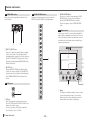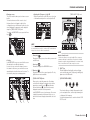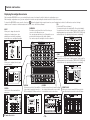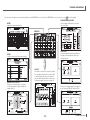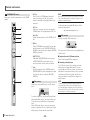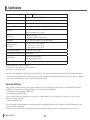
1
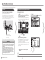
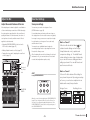
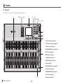
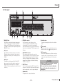
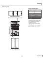
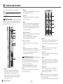
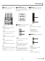
TF5 / TF3 / TF1 DIGITAL MIXING CONSOLE Quick Guide Thank you for choosing a Yamaha TF5/TF3/TF1 Digital Mixing Console. To take full advantage of the superior features and performance offered by your TF-series console, and to enjoy years of trouble-free use, please read this document carefully before operating your console. EN Contents 6-11 6-12 6-13 6-14 1.Precautions................................................................................................. 5 2.Introduction................................................................................................. 7 2-1 Intended user....................................................................................... 7 2-2 Intended usage.................................................................................... 7 2-3 Included items..................................................................................... 7 2-4Documentation..................................................................................... 7 2-5 Updating the product's software and firmware................................... 7 2-6 Nomenclature used in this document.................................................. 7 7.Setup.......................................................................................................... 21 7-1 Setting the internal clock................................................................... 21 7-2 Initialization (factory reset)................................................................. 21 7-3 Attaching the optional Rack Mount Kit (RK5014) (TF1 only)............. 21 8.Specifications............................................................................................ 22 3. Workflow Overview..................................................................................... 8 Connect............................................................................................... 8 Use Presets to Set Up Each Channel.................................................. 8 Adjust the Mix...................................................................................... 9 Save Your Settings............................................................................... 9 4.Panels........................................................................................................ 10 4-1 Top panel........................................................................................... 10 4-2 Rear panel......................................................................................... 11 5.Connections.............................................................................................. 12 5-1 Connecting inputs.............................................................................. 12 5-2 Connecting outputs........................................................................... 13 6. Controls and functions............................................................................. 14 6-1 6-2 6-3 6-4 6-5 6-6 6-7 6-8 6-9 6-10 Channel Strip section......................................................................... 14 ST IN (Stereo Input) section............................................................... 14 FX section.......................................................................................... 15 USER DEFINED KEYS section........................................................... 15 MUTE section..................................................................................... 15 METER section................................................................................... 15 PHONES section................................................................................ 15 FADER BANK section........................................................................ 16 TAP section........................................................................................ 16 SENDS ON FADER section................................................................ 16 TF series Quick Guide Display section.................................................................................. 16 STEREO/MASTER section................................................................. 20 iPad connector................................................................................... 20 USB connector................................................................................... 20 -2- PRÉCAUTIONS CONCERNANT LA SÉCURITÉ 1 2 3 4 5 6 7 The above warning is located on the rear of the unit. L’avertissement ci-dessus est situé sur l’arrière de l’unité. Explanation of Graphical Symbols Explication des symboles The lightning flash with arrowhead symbol within an equilateral triangle is intended to alert the user to the presence of uninsulated “dangerous voltage” within the product’s enclosure that may be of sufficient magnitude to constitute a risk of electric shock to persons. L’éclair avec une flèche à l’intérieur d’un triangle équilatéral est destiné à attirer l’attention de l’utilisateur sur la présence d’une « tension dangereuse » non isolée à l’intérieur de l’appareil, pouvant être suffisamment élevée pour constituer un risque d’électrocution. The exclamation point within an equilateral triangle is intended to alert the user to the presence of important operating and maintenance (servicing) instructions in the literature accompanying the product. Le point d’exclamation à l’intérieur d’un triangle équilatéral est destiné à attirer l’attention de l’utilisateur sur la présence d’instructions importantes sur l’emploi ou la maintenance (réparation) de l’appareil dans la documentation fournie. IMPORTANT SAFETY INSTRUCTIONS 1 2 3 4 5 6 7 Read these instructions. Keep these instructions. Heed all warnings. Follow all instructions. Do not use this apparatus near water. Clean only with dry cloth. Do not block any ventilation openings. Install in accordance with the manufacturer’s instructions. 8 Do not install near any heat sources such as radiators, heat registers, stoves, or other apparatus (including amplifiers) that produce heat. 9 Do not defeat the safety purpose of the polarized or groundingtype plug. A polarized plug has two blades with one wider than the other. A grounding type plug has two blades and a third grounding prong. The wide blade or the third prong are provided for your safety. If the provided plug does not fit into your outlet, consult an electrician for replacement of the obsolete outlet. 10 Protect the power cord from being walked on or pinched particularly at plugs, convenience receptacles, and the point where they exit from the apparatus. 11 Only use attachments/accessories specified by the manufacturer. 12 Use only with the cart, stand, tripod, bracket, or table specified by the manufacturer, or sold with the apparatus. When a cart is used, use caution when moving the cart/apparatus combination to avoid injury from tip-over. 13 Unplug this apparatus during lightning storms or when unused for long periods of time. 14 Refer all servicing to qualified service personnel. Servicing is required when the apparatus has been damaged in any way, such as power-supply cord or plug is damaged, liquid has been spilled or objects have fallen into the apparatus, the apparatus has been exposed to rain or moisture, does not operate normally, or has been dropped. Lire ces instructions. Conserver ces instructions. Tenir compte de tous les avertissements. Suivre toutes les instructions. Ne pas utiliser ce produit à proximité d’eau. Nettoyer uniquement avec un chiffon propre et sec. Ne pas bloquer les orifices de ventilation. Installer l’appareil conformément aux instructions du fabricant. 8 Ne pas installer l’appareil à proximité d’une source de chaleur comme un radiateur, une bouche de chaleur, un poêle ou tout autre appareil (y compris un amplificateur) produisant de la chaleur. 9 Ne pas modifier le système de sécurité de la fiche polarisée ou de la fiche de terre. Une fiche polarisée dispose de deux broches dont une est plus large que l’autre. Une fiche de terre dispose de deux broches et d’une troisième pour le raccordement à la terre. Cette broche plus large ou cette troisième broche est destinée à assurer la sécurité de l’utilisateur. Si la fiche équipant l’appareil n’est pas compatible avec les prises de courant disponibles, faire remplacer les prises par un électricien. 10 Acheminer les cordons d’alimentation de sorte qu’ils ne soient pas piétinés ni coincés, en faisant tout spécialement attention aux fiches, prises de courant et au point de sortie de l’appareil. 11 Utiliser exclusivement les fixations et accessoires spécifiés par le fabricant. 12 Utiliser exclusivement le chariot, le stand, le trépied, le support ou la table recommandés par le fabricant ou vendus avec cet appareil. Si l’appareil est posé sur un chariot, déplacer le chariot avec précaution pour éviter tout risque de chute et de blessure. 13 Débrancher l’appareil en cas d’orage ou lorsqu’il doit rester hors service pendant une période prolongée. 14 Confier toute réparation à un personnel qualifié. Faire réparer l’appareil s’il a subi tout dommage, par exemple si la fiche ou le cordon d’alimentation est endommagé, si du liquide a coulé ou des objets sont tombés à l’intérieur de l’appareil, si l’appareil a été exposé à la pluie ou à de l’humidité, si l’appareil ne fonctionne pas normalement ou est tombé. AVERTISSEMENT POUR RÉDUIRE LES RISQUES D’INCENDIE OU DE DÉCHARGE ÉLECTRIQUE, N’EXPOSEZ PAS CET APPAREIL À LA PLUIE OU À L’HUMIDITÉ. (UL60065_03) WARNING TO REDUCE THE RISK OF FIRE OR ELECTRIC SHOCK, DO NOT EXPOSE THIS APPARATUS TO RAIN OR MOISTURE. (UL60065_03) -3- TF series Quick Guide FCC INFORMATION (U.S.A.) 1. IMPORTANT NOTICE: DO NOT MODIFY THIS UNIT! This product, when installed as indicated in the instructions contained in this manual, meets FCC requirements. Modifications not expressly approved by Yamaha may void your authority, granted by the FCC, to use the product. 2. IMPORTANT: When connecting this product to accessories and/or another product use only high quality shielded cables. Cable/s supplied with this product MUST be used. Follow all installation instructions. Failure to follow instructions could void your FCC authorization to use this product in the USA. ADVARSEL! Lithiumbatteri—Eksplosionsfare ved fejlagtig håndtering. Udskiftning må kun ske med batteri af samme fabrikat og type. Levér det brugte batteri tilbage til leverandoren. VARNING Explosionsfara vid felaktigt batteribyte. Använd samma batterityp eller en ekvivalent typ som rekommenderas av apparattillverkaren. Kassera använt batteri enligt fabrikantens instruktion. VAROITUS Paristo voi räjähtää, jos se on virheellisesti asennettu. Vaihda paristo ainoastaan laitevalmistajan suosittelemaan tyyppiin. Hävitä käytetty paristo valmistajan ohjeiden mukaisesti. (lithium caution) 3. NOTE: This product has been tested and found to comply with the requirements listed in FCC Regulations, Part 15 for Class “B” digital devices. Compliance with these requirements provides a reasonable level of assurance that your use of this product in a residential environment will not result in harmful interference with other electronic devices. This equipment generates/uses radio frequencies and, if not installed and used according to the instructions found in the users manual, may cause interference harmful to the operation of other electronic devices. Compliance with FCC regulations does not guarantee that interference will not occur in all installations. If this product is found to be the source of interference, which can be determined by turning the unit “OFF” and “ON”, please try to eliminate the problem by using one of the following measures: Relocate either this product or the device that is being affected by the interference. Utilize power outlets that are on different branch (circuit breaker or fuse) circuits or install AC line filter/s. In the case of radio or TV interference, relocate/ reorient the antenna. If the antenna lead-in is 300 ohm ribbon lead, change the lead-in to co-axial type cable. If these corrective measures do not produce satisfactory results, please contact the local retailer authorized to distribute this type of product. If you can not locate the appropriate retailer, please contact Yamaha Corporation of America, Electronic Service Division, 6600 Orangethorpe Ave, Buena Park, CA90620 The above statements apply ONLY to those products distributed by Yamaha Corporation of America or its subsidiaries. * This applies only to products distributed by YAMAHA CORPORATION OF AMERICA. TF series Quick Guide •Dit apparaat bevat een lithium batterij voor geheugen back-up. •This apparatus contains a lithium battery for memory back-up. •Raadpleeg uw leverancier over de verwijdering van de batterij op het moment dat u het apparaat ann het einde van de levensduur of gelieve dan contact op te nemen met de vertegenwoordiging van Yamaha in uw land. •For the removal of the battery at the moment of the disposal at the end of life please consult your retailer or Yamaha representative office in your country. •Gooi de batterij niet weg, maar lever hem in als KCA. •Do not throw away the battery. Instead, hand it in as small chemical waste. (lithium disposal) NEDERLAND / THE NETHERLANDS (class B) This product contains a battery that contains perchlorate material. Perchlorate Material—special handling may apply, See www.dtsc.ca.gov/hazardouswaste/perchlorate. * This applies only to products distributed by YAMAHA CORPORATION OF AMERICA. (Perchlorate) In Finland: Laite on liitettävä suojamaadoituskoskettimilla varustettuun pistorasiaan. In Norway: Apparatet må tilkoples jordet stikkontakt. In Sweden: Apparaten skall anslutas till jordat uttag. (class I hokuo) COMPLIANCE INFORMATION STATEMENT (DECLARATION OF CONFORMITY PROCEDURE) Responsible Party : Yamaha Corporation of America Address : 6600 Orangethorpe Ave., Buena Park, Calif. 90620 Telephone : 714-522-9011 Type of Equipment : Digital Mixing Console Model Name : TF5/TF3/TF1 This device complies with Part 15 of the FCC Rules. Operation is subject to the following two conditions: 1)this device may not cause harmful interference, and 2)this device must accept any interference received including interference that may cause undesired operation. See user manual instructions if interference to radio reception is suspected. * This applies only to products distributed by YAMAHA CORPORATION OF AMERICA (FCC DoC) IMPORTANT NOTICE FOR THE UNITED KINGDOM Connecting the Plug and Cord WARNING: THIS APPARATUS MUST BE EARTHED IMPORTANT. The wires in this mains lead are coloured in accordance with the following code: GREEN-AND-YELLOW :EARTH BLUE :NEUTRAL BROWN :LIVE As the colours of the wires in the mains lead of this apparatus may not correspond with the coloured markings identifying the terminals in your plug proceed as follows: The wire which is coloured GREEN-and-YELLOW must be connected to the terminal in the plug which is marked by the letter E or by the safety earth symbol or colored GREEN or GREEN-and-YELLOW. The wire which is coloured BLUE must be connected to the terminal which is marked with the letter N or coloured BLACK. The wire which is coloured BROWN must be connected to the terminal which is marked with the letter L or coloured RED. (3 wires) 이 기기는 가정용(B급) 전자파적합기기로서 주로 가정에서 사용하는 것을 목적으로 하며, 모든 지역에서 사용할 수 있습니다. (class b korea) -4- 1. Precautions PLEASE READ CAREFULLY BEFORE PROCEEDING Please keep this manual in a safe place for future reference. WARNING Always follow the basic precautions listed below to avoid the possibility of serious injury or even death from electrical shock, short-circuiting, damages, fire or other hazards. These precautions include, but are not limited to, the following: Power supply/power cord • Do not place the power cord near heat sources such as heaters or radiators, and do not excessively bend or otherwise damage the cord, place heavy objects on it, or place it in a position where anyone could walk on, trip over, or roll anything over it. • Only use the voltage specified as correct for the device. The required voltage is printed on the name plate of the device. • Use only the supplied power cord/plug. If you intend to use the device in an area other than in the one you purchased, the included power cord may not be compatible. Please check with your Yamaha dealer. • Check the electric plug periodically and remove any dirt or dust which may have accumulated on it. • Be sure to connect to an appropriate outlet with a protective grounding connection. Improper grounding can result in electrical shock, damage to the device(s), or even fire. Do not open • This device contains no user-serviceable parts. Do not open the device or attempt to disassemble the internal parts or modify them in any way. If it should appear to be malfunctioning, discontinue use immediately and have it inspected by qualified Yamaha service personnel. Water warning • Do not expose the device to rain, use it near water or in damp or wet conditions, or place on it any containers (such as vases, bottles or glasses) containing liquids which might spill into any openings. If any liquid such as water seeps into the device, turn off the power immediately and unplug the power cord from the AC outlet. Then have the device inspected by qualified Yamaha service personnel. • Never insert or remove an electric plug with wet hands. Fire warning • Do not put burning items, such as candles, on the unit. A burning item may fall over and cause a fire. If you notice any abnormality • When one of the following problems occur, immediately turn off the power switch and disconnect the electric plug from the outlet. Then have the device inspected by Yamaha service personnel. -The power cord or plug becomes frayed or damaged. -It emits unusual smells or smoke. -Some object has been dropped into the device. -There is a sudden loss of sound during use of the device. • If this device should be dropped or damaged, immediately turn off the power switch, disconnect the electric plug from the outlet, and have the device inspected by qualified Yamaha service personnel. CAUTION Always follow the basic precautions listed below to avoid the possibility of physical injury to you or others, or damage to the device or other property. These precautions include, but are not limited to, the following: Power supply/power cord • When removing the electric plug from the device or an outlet, always hold the plug itself and not the cord. Pulling by the cord can damage it. • Remove the electric plug from the outlet when the device is not to be used for extended periods of time, or during electrical storms. Location • Do not place the device in an unstable position where it might accidentally fall over. • Do not block the vents. This device has ventilation holes at the top/front/rear to prevent the internal temperature from becoming too high. In particular, do not place the device on its side or upside down. Inadequate ventilation can result in overheating, possibly causing damage to the device(s), or even fire. • Do not place the device in a location where it may come into contact with corrosive gases or salt air. Doing so may result in malfunction. • Before moving the device, remove all connected cables. -5- • When setting up the device, make sure that the AC outlet you are using is easily accessible. If some trouble or malfunction occurs, immediately turn off the power switch and disconnect the plug from the outlet. Even when the power switch is turned off, electricity is still flowing to the product at the minimum level. When you are not using the product for a long time, make sure to unplug the power cord from the wall AC outlet. • When transporting or moving the device, always use two or more people. Attempting to lift the device by yourself may damage your back, result in other injury, or cause damage to the device itself. Connections • Before connecting the device to other devices, turn off the power for all devices. Before turning the power on or off for all devices, set all volume levels to minimum. Maintenance • Remove the power plug from the AC outlet when cleaning the device. Handling caution • Do not insert your fingers or hands in any gaps or openings on the device (vents, etc.). • Avoid inserting or dropping foreign objects (paper, plastic, metal, etc.) into any gaps or openings on the device (vents, etc.) If this happens, turn off the power immediately and unplug the power cord from the AC outlet. Then have the device inspected by qualified Yamaha service personnel. • Do not rest your weight on the device or place heavy objects on it, and avoid use excessive force on the buttons, switches or connectors. • Do not use headphones for a long period of time at a high or uncomfortable volume level, since this can cause permanent hearing loss. If you experience any hearing loss or ringing in the ears, consult a physician. Backup battery • Do not replace the backup battery by yourself. Doing so may cause an explosion and/or damage to the device(s). If the backup battery power is fully depleted, have qualified Yamaha service personnel replace the battery. Yamaha cannot be held responsible for damage caused by improper use or modifications to the device, or data that is lost or destroyed. TF series Quick Guide Precautions NOTICE To avoid the possibility of malfunction/damage to the product, damage to data, or damage to other property, follow the notices below. Handling and maintenance • Do not use the device in the vicinity of a TV, radio, stereo equipment, mobile phone, or other electric devices. Otherwise, the device, TV, or radio may generate noise. • Do not expose the device to excessive dust or vibration, or extreme cold or heat (such as in direct sunlight, near a heater, or in a car during the day), in order to prevent the possibility of panel disfiguration, unstable operation, or damage to the internal components. • Do not place vinyl, plastic or rubber objects on the device, since this might discolor the panel. When cleaning the device, use a dry and soft cloth. Do not use paint thinners, solvents, cleaning fluids, or chemicalimpregnated wiping cloths. • Condensation can occur in the device due to rapid, drastic changes in ambient temperature—when the device is moved from one location to another, or air conditioning is turned on or off, for example. Using the device while condensation is present can cause damage. If there is reason to believe that condensation might have occurred, leave the device for several hours without turning on the power until the condensation has completely dried out. • Avoid setting all equalizer controls and faders to their maximum. Depending on the condition of the connected devices, doing so may cause feedback and may damage the speakers. • Do not apply oil, grease, or contact cleaner to the faders. Doing so may cause problems with electrical contact or fader motion. • When turning on the AC power in your audio system, always turn on the power amplifier LAST, to avoid speaker damage. When turning the power off, the power amplifier should be turned off FIRST for the same reason. • Always turn the power off when the device is not in use. TF series Quick Guide Saving your data • This product utilizes an internal backup battery that is used to retain your data after the product is turned off. The backup battery is a consumable item. We recommend your replace the backup battery before it is depleted, otherwise data retained in memory will be lost. When the backup battery needs to be replaced, "Low Battery" or "No Battery" will appear on the display. In this case, contact your Yamaha dealer and have qualified Yamaha service personnel replace the backup battery. The average life of the backup battery is approximately five years, depending on operating conditions. * The follow data are retained by the backup battery. • Internal clock information No other data relies on the backup battery, therefore no other data will be lost if the backup battery is depleted. • This product regularly saves the state of its workspace so that it can return to the previous state when the product is turned on. To ensure that the state is saved properly, wait at least 10 seconds after performing the last operation before turning the product off. Connectors • XLR-type connectors are wired as follows (IEC60268 standard): pin 1: ground, pin 2: hot (+), and pin 3: cold (–). Information • Copying of the commercially available musical data including but not limited to MIDI data and/or audio data is strictly prohibited except for your personal use. • The illustrations and LCD screens as shown in this manual are for instructional purposes only, and may appear somewhat different from those on your device. • Windows is a registered trademark of Microsoft® Corporation in the United States and other countries. • Apple, iOS, iPad and iPod are trademarks of Apple Inc., registered in the U.S. and other countries. • The company names and product names in this manual are the trademarks or registered trademarks of their respective companies. -6- Information for Users on Collection and Disposal of Old Equipment This symbol on the products, packaging, and/or accompanying documents means that used electrical and electronic products should not be mixed with general household waste. For proper treatment, recovery and recycling of old products, please take them to applicable collection points, in accordance with your national legislation and the Directives 2002/96/EC. By disposing of these products correctly, you will help to save valuable resources and prevent any potential negative effects on human health and the environment which could otherwise arise from inappropriate waste handling. For more information about collection and recycling of old products, please contact your local municipality, your waste disposal service or the point of sale where you purchased the items. [For business users in the European Union] If you wish to discard electrical and electronic equipment, please contact your dealer or supplier for further information. [Information on Disposal in other Countries outside the European Union] This symbol is only valid in the European Union. If you wish to discard these items, please contact your local authorities or dealer and ask for the correct method of disposal. (weee_eu_en_01) European Models Purchaser/User Information specified in EN55103-1:2009 and EN55103-2:2009. Inrush Current:5.6A (on initial switch-on) 4.9A (after a supply interruption of 5s) Conforms to Environments: E1, E2, E3 and E4 2. Introduction 2-1 Intended user This product was designed for users who are familiar with using analog mixers as part of a PA system. 2-2 Intended usage This product was designed to mix multiple audio sources, such as live band instruments or audio devices used at corporate events. 2-3 Included items Accessories • AC power cord • Quick Guide (this document) 2-4 Documentation Quick Guide (this document) This document primarily explains panel controls, functions, and basic operation of the product. Reference Manual (PDF; downloadable from the website) This document primarily explains details about functions, production operation, and effects parameters. The Refernece Manual is available on the Yamaha Pro Audio website. http://www.yamahaproaudio.com/ Using the Reference Manual The Reference Manual is an electronic file in PDF format. You can read this document on a computer. Use Adobe® Reader® to read this book on screen, search for words very quickly, print specific pages, or click links to display sections of special interest. The ability to search for words, or to follow links directly to relevant sections in the document, are helpful attributes of this electronic file format. We encourage you to take advantage of these benefits. You can download the latest Adobe Reader application from the website listed below. 2-5 Updating the product's software and firmware 2-6 Nomenclature used in this document Software In this document, switch-type controls on the panel are called “keys.” Your TF-series console can be used with a variety of utility software. • TF Editor This application enables you to set up and operate the console from a connected computer. You can also use the application to back up console settings or set console parameters without connecting the console. Controls located on the panel are enclosed in [square brackets] (e.g., the [CUE] key) to distinguish them from virtual buttons and knobs displayed on screen. For certain controls, the name of the section appears before the brackets (e.g., SENDS ON FADER [AUX1] key). • TF mobile control application This app allows you to remote control your TF-series console using an iPad and a Wi-Fi connection. • Yamaha Steinberg USB Driver This driver software is required when connecting the console to your computer. It supports up to 34 channels of audio input and 34 channels of audio output. Information about the software described here is available on the Yamaha Pro Audio website. http://www.yamahaproaudio.com/ Information about downloading, installing and setting up the software described here is available on the website listed above. In addition, refer to the installation guide that is included with each program. Firmware The firmware contained in your TF-series console can be updated to take advantage of new features, feature improvements, and bug fixes. Details about updating the firmware are available online. http://www.yamahaproaudio.com/ For information about updating and setting up the console, please refer to the firmware update guide available on the website. The model number, serial number, power requirements, etc., may be found on or near the name plate, which is at the rear of the unit. You should note this serial number in the space provided below and retain this manual as a permanent record of your purchase to aid identification in the event of theft. Model No. Serial No. (rear_en_01) http://www.adobe.com/ -7- TF series Quick Guide 3. Workflow Overview Here's a brief overview of how to start mixing using a Presets. Connect Connectyour inputs and outputs Use Presets to Set Up Each Channel Connect your inputs and outputs Set up each channel Connect the instruments and mics. Connect output devices such as powered speakers. Input and output settings are ready to go when the console is shipped, so you can start mixing as soon as you make your connections (page 12). > Step 1 Select a channel by pressing its [SEL] key in the Channel Strip section. > Step 2 Press the Library key ( ) to access the Library and recall a Preset. The channel's [SEL] key lights, indicating that you can control the channel using the Display section. [SEL] key Display section Power switch AC IN connector Connect the included power cord. When your connections are finished, turn on the power. NOTICE •Rapidly turning the unit on and off in succession can cause it to malfunction. After turning the unit off, wait for at least 6 seconds before turning it on again. •This product regularly saves the state of its workspace so that it can return to the previous state when the product is turned on. To ensure that the state is saved properly, wait at least 10 seconds after performing the last operation before turning the product off. Library key ( ) > Step 3 Adjust the channel’s parameters. Adjust the input gain, EQ, compressor, and gate from the OVERVIEW screen and the individual configuration screens (page 18). Adjust the input gain on the INPUT screen so that the loudest sound that is input causes the center graph to light. Adjusting the input gain > Repeat steps 1 to 3 and set up each channel. NOTE You can set up channels without using Presets. For details about the available features and parameters, refer to the Reference Manual. TF series Quick Guide -8- Workflow Overview Adjust the Mix Save Your Settings Adjust the overall balance of the mix Save your settings After adjusting each channel, adjust the overall balance of the mix while doing a sound check. While listening to the main speakers, pay attention to the overall sound quality, the balance of each instrument, the volume of each performer's monitor, and the amount of effects applied to each instrument. You can save your entire mix setup as a Scene. (SCENE window g page 18) If several bands are performing on the same stage, or if a single performer’s mix or audio sources vary greatly from song to song, you can save a complete mix setup for each band or each song as a Scene, and easily switch between Scenes. You can also save individual channel setups by overwriting existing Presets or by saving them as new Presets in the Library screen. After fine-tuning the sound of each channel to suit each instrument or mic, you can save them as Presets and recreate that configuration anytime, easily. •Adjusting SENDS ON FADER for the level sent to AUX for each channel (page 16) •Muting all input channels or effects (page 15) •Turning effects on and off, adjusting the overall level of effects (page 15) MUTE Effects on/ off, effects level What is a "Preset"? ) that A Preset is a file stored in the Library ( contains channel settings such as the type of input (instrument or mic), equalizer and compression settings, etc. The default Presets contain settings for various types of instruments, so you can use them as a starting point when setting up a channel. You can edit Presets and save them as new Presets. What is a "Scene"? HINT A Scene is file that contains all the settings for every channel in your mix. By saving your setups as Scenes, you can load a complete mix in an instant and be ready for any situation. Using USER DEFINED KEYS Saving a Scene SENDS ON FADER Recalling a Scene When the console is in the default state, USER DEFINED KEYS (page 15) are configured as "Direct Scene Recall" keys. You can save a Scene by pressing and holding down one of the USER DEFINED KEYS, and recall a Scene by pressing one of the USER DEFINED KEYS. -9- TF series Quick Guide 4. Panels 4-1 Top panel The top panel of TF Series consoles is divided into the following sections. ① ⑬ ② ⑪ ③ ⑭ ④ ⑤ ⑥ ⑦ ⑧ 1Channel Strip section (page 14) 2ST IN (stereo input) section (page 14) 3FX (effects) section (page 15) 4USER DEFINED KEYS section (page 15) ⑩ 5MUTE section (page 15) 6METER section (page 15) 7PHONES section (page 15) 8FADER BANK section (page 16) 9TAP key (page 16) ⑨ 0SENDS ON FADER section (page 16) aDisplay section (page 16) bSTEREO/MASTER section (page 20) ⑫ TF series Quick Guide - 10 - ciPad connector (page 20) dUSB connector (page 20) Panels 4-2 Rear panel ① ⑩ ⑨ ② ⑧ 1OMNI OUT jacks XLR-3-32 male output jacks that output analog audio signals. These jacks are used mainly to output AUX channels and STEREO channels. Nominal output level is +4 dBu. You can select which signal is output on the OMNI OUT screen. 2ST IN jacks Stereo input jacks that can be used for connecting a CD player or other line level device. These jacks are unbalanced female RCA jacks. Nominal input level is -10 dBV. 3INPUT jacks Combination jacks that support both XLR and TRS phone connectors. Use these jacks to connect mics and instruments. Nominal input level is -62 dBu to +10 dBu. The head amp setting for each jack is saved in memory. ⑦ ③ ⑥ ⑤ ④ 4NETWORK connector RJ-45 jack used to connect the console to a computer via an Ethernet cable (CAT5e or higher recommended). This connector is used mainly to control mix parameters or to edit Scene memories and Libraries from the dedicated "TF Editor" program or the iPad app. 8Ventilation holes To prevent overheating, do not block the ventilation holes. 5USB TO HOST connector USB connector used to connect the console to a computer, allowing the console to function as an audio interface. Supports input and output for 34 channels of 48 kHz, 24-bit audio. When using with a computer running Microsoft Windows, the Yamaha Steinberg USB Driver is required. 0AC IN connector Connect the included power cord. When connecting to a power outlet, first connect the power cord to the console, then connect the power cord to the power outlet. 6FOOT SW jack Used for connecting an optional FC5 foot switch. You can use the connected foot switch as an effect bypass switch, a mute switch, or use it to tap the delay time. 9 Power switch When the switch is in the When the switch is in the position, the power is on. position, the power is off. CAUTION •Make sure the unit is turned off before connecting or disconnecting the power cord. •Disconnect the power cord from the outlet when the unit will not be used for extended periods of time (page 8). 7Expansion slot An expansion slot to be used in the future. - 11 - TF series Quick Guide 5. Connections 5-1 Connecting inputs Default signal routing for each channel CHANNEL Electric guitar or bass Keyboard or synthesizer Direct box Mic CH 1 : CH 16 CH 17 : CH 24 CH 25 : CH 32 CH 33 : CH 40 ST IN 1L ST IN 1R ST IN 2L ST IN 2R ANALOG INPUT TF5 TF3 TF1 INPUT 1 : INPUT 16 INPUT 17 : INPUT 24 INPUT 25 : INPUT 32 INPUT 1 : INPUT 8 ST IN 1L ST IN 1R ST IN 2L ST IN 2R INPUT 1 : INPUT 16 INPUT 17 : INPUT 24 INPUT 1 : INPUT 8 INPUT 9 : INPUT 16 ST IN 1L ST IN 1R ST IN 2L ST IN 2R INPUT 1 : INPUT 16 INPUT 1 : INPUT 8 INPUT 9 : INPUT 16 : ST IN 1L ST IN 1R ST IN 2L ST IN 2R Default signal routing for each channel is shown above. To change the signal routing, use the INPUT screen (page 18). HINT Computer (DAW software) USB 2.0 FC5 (optional) TF series Quick Guide - 12 - What if I'm using condenser mics? Phantom power must be supplied to condenser mics. Some direct boxes also need phantom power. When using phantom power, first set "+48V Master" on the SYSTEM SETUP screen to on, then turn phantom power on or off for each channel on the corresponding channel's INPUT screen. Make sure you turn phantom power off if it is not needed. For more details, refer to the Reference Manual. Why can't I hear anything? • Is the fader that corresponds to the desired INPUT jack raised? • Does the input select for each channel match each INPUT jack? • Is the channel's head amp gain set too low? • Is the channel's [ON] key pressed? • Is the channel muted? Connections 5-2 Connecting outputs Default signal routing for each output jack Powered speakers (floor monitors) OMNI OUT 1 OMNI OUT 2 AUX1 OUT AUX2 OUT : OMNI OUT 12 OMNI OUT 13 OMNI OUT 14 OMNI OUT 15 (L) OMNI OUT 16 (R) : AUX12 OUT MONITOR L OUT MONITOR R OUT STEREO L OUT STEREO R OUT Each OMNI OUT jack is configured by default to output a bus. You can change the bus that is output on the SYSTEM OMNI OUT PATCH screen. The OMNI OUT jacks can be configured to output the following signals. AUX1–AUX20, STEREO L, STEREO R, SUB, MONITOR L, MONITOR R, NO ASSIGN (no output signal assigned). Powered speakers (front speakers) - 13 - TF series Quick Guide 6. Controls and functions This section briefly introduces the console's features. NOTE For details about each feature and parameter, refer to the Reference Manual. 6-1 Channel Strip section Similarly to a channel module of a traditional analog mixer, a Channel Strip allows you to manually control the main parameters of the channel. ① 2[CUE] key Used to select the channel that will be cue-controlled. The key lights when the CUE is on. 5Channel name display Displays the name, ID, or port name that is assigned to the corresponding channel. It also serves as the +48V, GATE, and COMP indicator, and displays the fader value. ⑤ ⑥ 6Channel color indicator Lights in the color assigned to the corresponding channel. 7Fader Adjusts the channel’s signal level. In SENDS ON FADER mode, the fader allows you to adjust the signal level sent from the corresponding channel to the currently selected AUX or FX bus. 1[SEL] key Used to select the channel that you will control. Pressing this key will cause the key to light, which indicates that you can control the channel on the display. For stereo channels, you can press the [SEL] key to switch between controlling the left and right channel of the stereo pair. TF series Quick Guide ② 4[ON] key Turns the corresponding channel on and off. The key lights when the channel is on. In SENDS ON FADER mode, the key functions as an on/off switch for signals sent from the corresponding channel to the currently selected AUX or FX bus. ② ③ ④ ⑦ ① 3Meter LEDs Indicate the audio signal level of the corresponding input or output channel. 6-2 ST IN (Stereo Input) section This section controls the stereo inputs. ST IN1 is used as the playback channel for iOS devices connected to the iPad connector or audio files stored in the connected USB storage device. ST IN2 is used as the playback channel for signals received from the USB TO HOST connector (USB IN33/34). You can switch the input signals for both ST IN1 and ST IN2 from the INPUT screen. ③ ④ ⑤ 1[SEL] key Used to select the ST IN channel that you will control. You can press the [SEL] key to switch between controlling the left and right channel of the stereo pair. 2[CUE] key Used as the cue monitor key for the ST IN channel. The key lights when the cue is on. 3Meter LEDs Indicate the audio signal level of the corresponding input or output channel. 4[ON] key Turns the corresponding ST IN channel on and off. The key lights when the channel is on. In SENDS ON FADER mode, turns the signal sent to the AUX or FX bus on and off. 5[LEVEL] knob Adjusts the signal level of the corresponding ST IN channel. In SENDS ON FADER mode, adjusts the signal sent to the AUX or FX bus. HINT For TF5 and TF3 consoles, ST IN can also be controlled using INPUT 2 in the FADER BANK. - 14 - Controls and functions 6-4 USER DEFINED KEYS section 6-3 FX section Allows you to control the FX RTN channels. ① ② ③ ④ ⑤ 6-6 METER section These keys can be customized to control the desired function. Various functions are assigned by default, such as Direct Scene Recall. Used to monitor audio signal level and control the CUE feature. ① ② 6-5 MUTE section 1[EDIT] key Displays the FX SEND screen. The key lights while the FX SEND screen is displayed. Used to mute all channels in a mute group. ① 2[CUE] key Used as the cue monitor key for the corresponding FX channel. The key lights when the CUE is on. 3Meter LEDs Indicate the audio signal level of the corresponding FX channel. 4[ON] key Turns the corresponding FX channel on and off. 5[LEVEL] knob Adjusts the total output level of the corresponding FX channel. HINT For TF5 and TF3 consoles, FX can also be controlled using INPUT 2 in the FADER BANK. ② 1[INPUT] key Allows you to mute all input channels. The key lights when the mute group is muted. 2[FX] key Allows you to mute the FX module. Insertion effects for channels in AUX9/10–AUX19/20 are bypassed. The key lights when the mute group is muted. HINT You can remove certain input and FX channels from the mute group by turning MUTE SAFE on for the desired channels. 1Meter LEDs Indicate the audio signal level of the STEREO or CUE bus. 2[CLEAR] key (CLEAR CUE key) Turns off the CUE for all channels. The key lights when the CUE is turned on. 6-7 PHONES section ① ② 1[PHONES] jack This headphones jack is used to monitor signals selected for MONITOR or CUE. 2[LEVEL] knob Controls the level of the [PHONES] jack output. - 15 - TF series Quick Guide Controls and functions 6-8 FADER BANK section 6-10 SENDS ON FADER section Allows you to quickly assign different channels to the console’s faders. Switches each channel strip to temporarily control the SEND LEVEL and SEND ON of the designated bus. 1[SENDS ON FADER] keys Press a key to set the corresponding bus to SENDS ON FADER mode. The key you pressed lights to indicate SENDS ON FADER mode is enabled. Press the key again to release SENDS ON FADER mode. 6-11 Display section ① Allows to you control the console by interacting with the graphic interface displayed on the touchscreen. You can also use the knobs to perform fine adjustments. You can dive further into various features by pressing the keys to display contextual menus. ② ① 1[INPUT1], [INPUT2] keys Allow you to change the channels that are assigned to the console’s faders. The keys light to indicate which fader bank is currently selected. You can press the [INPUT1] and [INPUT2] keys at the same time to light both keys and display the GROUP BANK in the Channel Strip section. ① ② ③ ④ 2[OUTPUT] key Displays the OUTPUT BANK in the Channel Strip section. You can press the [INPUT2] and [OUTPUT] keys at the same time to light both keys and display the CUSTOM FADER BANK in the Channel Strip section. ⑤ 6-9 TAP section ⑦ 1Display The display is a multitouch capable touchscreen that you can operate with your fingers. You can touch, double-touch, slide, swipe, and pinch in and out to interact with the items shown on the display. ① 1[TAP] key Allows you to tap and set the delay time used for effects on FX1/FX2 and AUX9/10–AUX19/20. The key flashes in time with the tempo. The tempo you tap on the [TAP] key is applied to effects that have “Sync” set to “On”. TF series Quick Guide ⑥ - 16 - Controls and functions •Changing screens The screen switches when you touch an on-screen button. You can touch an area of the screen to select that area, then touch it again to switch to the configuration screen for that area. A pink selection area is displayed if a parameter can be adjusted using the [TOUCH AND TURN] knob. To return to the OVERVIEW screen, press the Home key ( ). •Adjusting the Q (steepness) of the EQ When in manual mode on the EQ screen, select one of the handles and pinch in or out to adjust the Q. [TOUCH AND TURN] knob NOTE This functionality is not available when multiple parameters can be controlled by one knob (i.e., 1-knob mode). Use the button at the top of the screen to switch to manual mode. •Scrolling In the OVERVIEW screen, you can slide the screen left and right to view different channels. In some screens, such as the channel screen or the channel edit screen, you can slide the screen up and down to view other items on the screen. To scroll quickly, simply use a swiping gesture. 2Library key ( ) Displays the Library screen, from which you can recall saved Presets. 3Home key ( ) Returns the display to the OVERVIEW screen. 4Menu key ( ) Displays the menu for the current operation. The key lights when a menu is available. 5[TOUCH AND TURN] knob Allows you to control the parameter of the feature selected on the display. As shown below, touch the parameter you want to control (1) and then turn the knob as desired (2). A pink selection area is displayed around the selected parameter. In the OVERVIEW screen, touch an area of the screen to adjust the parameter in that area. In this case, a pink selection area is displayed around the selected area. - 17 - HINT What is “1-knob” mode? 1-knob mode allows you to control multiple EQ or compressor parameters with just one knob. When 1-knob mode is enabled, parameters cannot be adjusted individually. You can turn 1-knob mode on and off from the EQ and compressor screens. 6[SHIFT] key Provides additional functionality, such as allowing you to switch between the F (frequency) and G (gain) parameters of the EQ handle. 7[USER DEFINED KNOBS] These knobs allow you to adjust the parameters that you've assigned to them, such as input channel gain or high-pass filter frequency. You can assign parameters to each knob in the USER SETUP screen. TF series Quick Guide Controls and functions Displaying the configuration screens While viewing the OVERVIEW screen, you can double-touch an area of a channel to switch to that area's configuration screen. While viewing a configuration screen, you can easily switch to another area by touching the desired area in the left side of the screen. To return to the OVERVIEW screen, press the Home key ( ) below the display. In the example shown here, we will explain how to switch to the different screens from the input channel screen. For details or information about other screens, refer to the Reference Manual. EQ Controls the EQ for each channel. OVERVIEW You can pinch in and out to adjust the Q of the selected handle. INPUT Provides an overall view of the mixer. From here you You can also use this screen to switch between 1-knob mode (for Allows you to change the stereo link can move to the different screens. adjusting parameters easily using the [TOUCH AND TURN] knob) You can swipe up and down to scroll through the screen setting, select an input source, turn and manual mode (for adjusting each parameter individually). and view the desired area of the visible channels. phantom power on and off, turn phasing You can also swipe left and right to view other channels. normal and reverse, and adjust input gain. COMP Allows you to configure the compressor for each channel. You can also use this screen to switch between 1-knob mode (for adjusting parameters easily using the [TOUCH AND TURN] knob) and manual mode (for adjusting each parameter individually). GATE Allows you to configure the noise gate for each channel. FX1/FX2 Used to select effects and edit their parameters. TF series Quick Guide ASSIGN Allows you to turn Recall Safe and Mute Safe on and off, assign the channel to a DCA, and adjust the SUB bus send level. CH VIEW Provides an overall view of a channel's settings. You can adjust settings on this screen or switch to the dedicated screen for each setting. - 18 - SEND TO AUX Allows you to set each channel's AUX bus send levels. Swipe left and right to view levels for other AUX buses. Controls and functions You can view the following screens by touching the buttons in the OVERVIEW screen. To return to the OVERVIEW screen, press the Home key ( ) below the display. CUE/MONITOR/OSCILLATOR Used to manage CUE/monitor source and control oscillators. METER Displays the input and output level. OVERVIEW USER SETUP Used to assign user-defined keys and knobs, configure custom fader banks, and set up other preferences. SCENE Used to recall previously saved mixer setups. INPUT/OUTPUT/TITLE LIST Allows you to record directly to a computer or USB storage device, play back audio files, manage titles, etc. CH VIEW Provides an overall view of a channel's settings. You can adjust settings on this screen or switch to the dedicated screen for each setting. You can also edit the Channel Name on this screen. For information about each screen, see page 18. SYSTEM SETUP Allows you to configure general mixer settings, as well as settings for OMNI OUT and Recall Safe. - 19 - TF series Quick Guide Controls and functions 6-12 STEREO/MASTER section Allows you to control the main parameters of the STEREO channel. ① ② ③ ④ ⑤ 1[SEL] key Used to select the STEREO channel that you will control. You can press the [SEL] key to switch between controlling the left and right channel of the stereo pair. 2[CUE] key Used as the cue monitor key for the corresponding STEREO channel. The key lights when the CUE is on. 3Meter LEDs Indicate the audio signal level of the STEREO or CUE bus. 4[ON] key Turns the STEREO channel on and off. The key lights when the channel is on. In SENDS ON FADER mode, the [ON] key turns the bus selected by the SENDS ON FADER key on and off. 5[MASTER] LED Lights when SENDS ON FADER mode is turned on. In SENDS ON FADER mode, the entire section becomes the master section for the selected bus. 6Fader Adjusts the output level of the STEREO channel. In SENDS ON FADER mode, the fader adjusts the signal level sent to the bus selected by the SENDS ON FADER key. ⑥ 6-13 iPad connector When using a USB storage device for recording, use a hard disk drive or other high-speed device. (USB memory drives are not guaranteed to function properly.) For information about compatible iOS devices, visit the Yamaha pro audio website. http://www.yamahaproaudio.com/ 6-14 USB connector Used for connecting USB memory drives. You can connect a USB memory drive and read/write data from/to the drive. Supported formats for USB memory drives Drives formatted using FAT32 are supported. Preventing accidental erasure Some USB memory drives offer a write-protect feature which prevents accidental data erasure. If you save important data on a USB memory drive, we recommend using the drive's write-protect feature to protect your data from being erased. Conversely, make sure the drive's write-protect feature is turned off before trying to save data to the drive. NOTE Allows you to connect an iOS device or a USB storage device. To connect an iOS device, use the dedicated cable that was included with the device. This connector allows you to use audio files on your iOS device as background music. When a USB storage device is connected, you can use the device to play audio files or record the mixer's output directly and save it as an audio file (format: WAV). TF series Quick Guide NOTE - 20 - The ACCESS indicator is displayed in the upper right of the screen while data is being accessed (read, written, erased, etc.). While this indicator is displayed, do not turn off the unit or disconnect the USB memory drive. The unit, the drive, and data stored on the drive could become damaged. 7. Setup This section explains how to set up the TF series console the first time you turn it on. 4 When finished, touch [OK]. 5 Press the Home key ( 7-1 Setting the internal clock Set the console’s internal clock, including the date, time, and format. The date and time set here is used as a timestamp when saving Scenes. 1 Touch the SYSTEM SETUP icon ). The OVERVIEW screen is displayed. . The SYSTEM SETUP screen is displayed. NOTE In addition to the internal clock, you can configure the following items. For details, refer to the Reference Manual. •AUX bus signal type •Network settings •OMNI OUT settings •Recall Safe channels 7-3 Attaching the optional Rack Mount Kit (RK5014) (TF1 only) The procedure is the same for the left and right sides of the console. The right side is shown here. 1 Prepare the console by removing the side pads. 1 Remove the two screws that secure each side pad. 2 Slide and remove the side pads as shown. ❶ 7-2 Initialization (factory reset) In the event that an internal memory error occurs or you have forgotten your password and cannot operate the console, you can use the following procedure to initialize the console. NOTE All information that you have stored in the unit will be erased when you initialize the unit. Use caution when performing this procedure. 2 Touch the TIME button. The screen for setting the time is displayed. ❷ 1 Turn on the console while holding down the Home key ( ). 2 When the maintenance screen appears, press the Initialize All Memories button. All settings will be restored to the factory defaults. 2 Attach the rack mount brackets. 1 Attach the rack mount brackets to the console using the 8 screws (4 per side) that were included with the Rack Mount Kit. 2 Make sure each bracket is firmly attached. 3 Slide the desired fields up and down to set the date and time. ❶ - 21 - TF series Quick Guide 8. Specifications Sampling Frequency Internal Clock Signal Delays Less than 2.6 ms, INPUT to OMNI OUT, Fs=48 kHz Fader 100 mm motorized, Resolution = 10-bit, +10 dB to –138 dB, –∞ dB all faders Frequency Response 48 kHz +0.5, –1.5 dB 20 Hz–20 kHz, refer to +4 dBu output @1kHz, INPUT to OMNI OUT Total Harmonic Distortion Less than 0.05% 20 Hz–20 kHz @+4 dBu into 600 Ω, INPUT to OMNI OUT, Input Gain=Min. Hum & Noise*3 –128 dBu typ., Equivalent Input Noise, Input Gain=Max., –85 dBu, Residual output noise, ST master off Dynamic Range 110 dB typ., DA Converter, 107 dB typ., INPUT to OMNI OUT, Input Gain=Min. Crosstalk@1 kHz –100 dB*1, adjacent INPUT/OMNI OUT channels, Input Gain=Min. Dimensions (W x H x D) and Net Weight TF5: 866 mm × 225 mm × 599 mm, 20.0 kg TF3: 716 mm × 225 mm × 599 mm, 17.0 kg TF1: 510 mm × 225 mm × 599 mm, 13.5 kg Power Requirements (wattage) TF5: 120 W; TF3: 110 W; TF1: 100 W Power Requirements (voltage and hertz) 100–240 V 50/60 Hz Temperature Range Operating temperature range: 0–40 °C Storage temperature range: -20–60 °C Included Accessories Quick Guide, Power Cord *2 *1 Crosstalk is measured with a –30 dB/octave filter@22 kHz. *2 Total Harmonic Distortion is measured with a –18 dB/octave filter@80 kHz. *3 Hum & Noise are measured with an A-Weight filter. * The contents of this manual apply to the latest specifications as of the printing date. Since Yamaha makes continuous improvements to the product, this manual may not apply to the specifications of your particular product. To obtain the latest manual, access the Yamaha website then download the manual file. Since specifications, equipment or separately sold accessories may not be the same in every locale, please check with your Yamaha dealer. Source code distribution For three years after the final factory shipment, you may request from Yamaha the source code for any portions of the product which are licensed under the GNU General Public License/GNU Lesser General Public License/RealNetworks Public Source License by writing to the following address: 10-1 Nakazawa-cho, Naka-ku, Hamamatsu, 430-8650, JAPAN Pro Audio Department, Yamaha Corporation The source code will be provided at no charge; however, we may require you to reimburse Yamaha for the cost of delivering the source code to you. The source code can be downloaded by visiting the following URL: http://www.yamahaproaudio.com/ • Note that we shall bear no responsibility whatsoever for any damage arising from changes (additions/deletions) made to the software for this product by a third party other than Yamaha (or party authorized by Yamaha). • Note that re-use of source code released to the public domain by Yamaha is not guaranteed. Yamaha shall not bear any responsibility whatsoever for the source code. TF series Quick Guide - 22 - For details of products, please contact your nearest Yamaha representative or the authorized distributor listed below. Die Einzelheiten zu Produkten sind bei Ihrer unten aufgeführten Niederlassung und bei Yamaha Vertragshändlern in den jeweiligen Bestimmungsländern erhältlich. Pour plus de détails sur les produits, veuillez-vous adresser à Yamaha ou au distributeur le plus proche de vous figurant dans la liste suivante. Para detalles sobre productos, contacte su tienda Yamaha más cercana o el distribuidor autorizado que se lista debajo. NORTH AMERICA CANADA Yamaha Canada Music Ltd. 135 Milner Avenue, Toronto, Ontario, M1S 3R1, Canada Tel: 416-298-1311 U.S.A. Yamaha Corporation of America 6600 Orangethorpe Avenue, Buena Park, CA 90620, U.S.A. Tel: 714-522-9011 CENTRAL & SOUTH AMERICA MEXICO Yamaha de México, S.A. de C.V. Av. Insurgentes Sur 1647 Piso 9, Col. San José Insurgentes, Delegación Benito Juárez, México, D.F., C.P. 03900 Tel: 55-5804-0600 BRAZIL Yamaha Musical do Brasil Ltda. Rua Joaquim Floriano, 913 - 4º andar, Itaim Bibi, CEP 04534-013 São Paulo, SP. BRAZIL Tel: 011-3704-1377 ARGENTINA Yamaha Music Latin America, S.A., Sucursal Argentina Olga Cossettini 1553, Piso 4 Norte, Madero Este-C1107CEK Buenos Aires, Argentina Tel: 011-4119-7000 VENEZUELA Yamaha Music Latin America, S.A., Sucursal Venezuela C.C. Manzanares Plaza P4 Ofic. 0401- Manzanares-Baruta Caracas Venezuela Tel: 58-212-943-1877 PANAMA AND OTHER LATIN AMERICAN COUNTRIES/ CARIBBEAN COUNTRIES Yamaha Music Latin America, S.A. Torre Banco General, Piso No.7, Marbella, Calle 47 y Aquilino de la Guardia, Ciudad de Panamá, República de Panamá Tel: +507-269-5311 PA37 EUROPE THE UNITED KINGDOM/IRELAND Yamaha Music Europe GmbH (UK) Sherbourne Drive, Tilbrook, Milton Keynes, MK7 8BL, U.K. Tel: 01908-366700 GERMANY Yamaha Music Europe GmbH Siemensstraße 22-34, 25462 Rellingen, Germany Tel: 04101-3030 SWITZERLAND/LIECHTENSTEIN Yamaha Music Europe GmbH Branch Switzerland in Zürich Seefeldstrasse 94, 8008 Zürich, Switzerland Tel: 044-387-8080 AUSTRIA/BULGARIA Yamaha Music Europe GmbH Branch Austria Schleiergasse 20, A-1100 Wien, Austria Tel: 01-60203900 CZECH REPUBLIC/HUNGARY/ ROMANIA/SLOVAKIA/SLOVENIA Yamaha Music Europe GmbH Branch Austria (Central Eastern Europe Office) Schleiergasse 20, A-1100 Wien, Austria Tel: 01-60203900 POLAND/LITHUANIA/LATVIA/ ESTONIA Yamaha Music Europe GmbH Branch Poland Office ul. Wrotkowa 14 02-553 Warsaw, Poland Tel: 022-500-2925 MALTA Olimpus Music Ltd. The Emporium, Level 3, St. Louis Street Msida MSD06 Tel: 02133-2144 NETHERLANDS/BELGIUM/ LUXEMBOURG Yamaha Music Europe Branch Benelux Clarissenhof 5-b, 4133 AB Vianen, Netherlands Tel: 0347-358 040 FRANCE AFRICA Yamaha Music Europe 7 rue Ambroise Croizat, Zone d’activites Pariest, 77183 Croissy-Beaubourg, France Tel: 01-64-61-4000 Yamaha Music Gulf FZE Office JAFZA 16-512, P.O.Box 17328, Jebel Ali - Dubai, UAE Tel: +971-4-881-5868 ITALY Yamaha Music Europe GmbH, Branch Italy Viale Italia 88, 20020 Lainate (Milano), Italy Tel: 02-935-771 MIDDLE EAST TURKEY Yamaha Music Europe GmbH Merkezi Almanya Türkiye İstanbul Şubesi Maslak Meydan Sokak No:5 Spring Giz Plaza Bağımsız Böl. No:3, 34398 Şişli İstanbul Tel: +90-212-999-8010 SPAIN/PORTUGAL Yamaha Music Europe GmbH Ibérica, Sucursal en España Ctra. de la Coruna km. 17,200, 28231 Las Rozas (Madrid), Spain Tel: +34-91-639-88-88 CYPRUS Yamaha Music Europe GmbH Siemensstraße 22-34, 25462 Rellingen, Germany Tel: 04101-3030 GREECE Philippos Nakas S.A. The Music House 147 Skiathou Street, 112-55 Athens, Greece Tel: 01-228 2160 OTHER COUNTRIES SWEDEN/FINLAND/ICELAND Yamaha Music Gulf FZE Office JAFZA 16-512, P.O.Box 17328, Jebel Ali - Dubai, U.A.E Tel: +971-4-881-5868 Yamaha Music Europe GmbH Germany filial Scandinavia JA Wettergrensgata 1, Västra Frölunda, Sweden Tel: +46 31 89 34 00 ASIA DENMARK Yamaha Music Europe GmbH, Tyskland – filial Denmark Generatorvej 8B, DK-2730 Herlev, Denmark Tel: 44 92 49 00 THE PEOPLE’S REPUBLIC OF CHINA Yamaha Music & Electronics (China) Co.,Ltd. 2F, Yunhedasha, 1818 Xinzha-lu, Jingan-qu, Shanghai, China Tel: 400-051-7700 NORWAY Yamaha Music Europe GmbH Germany Norwegian Branch Grini Næringspark 1, N-1361 Østerås, Norway Tel: 67 16 78 00 MALAYSIA Yamaha Music (Malaysia) Sdn., Bhd. No.8, Jalan Perbandaran, Kelana Jaya, 47301 Petaling Jaya, Selangor, Malaysia Tel: 03-78030900 SINGAPORE Yamaha Music (Asia) Private Limited Block 202 Hougang Street 21, #02-00, Singapore 530202, Singapore Tel: 65-6747-4374 TAIWAN Yamaha Music & Electronics Taiwan Co.,Ltd. 3F, No.6, Section 2 Nan-Jing East Road, Taipei, Taiwan R.O.C. Tel: 02-2511-8688 THAILAND Siam Music Yamaha Co., Ltd. 3, 4, 15 and 16th floor, Siam Motors Building, 891/1 Rama 1 Road, Wangmai, Pathumwan, Bangkok 10330, Thailand Tel: 02-215-2622 VIETNAM Yamaha Music Vietnam Company Limited 15th Floor, Nam A Bank Tower, 201-203 Cach Mang Thang Tam St., Ward 4, Dist.3, Ho Chi Minh City, Vietnam Tel: +84-8-3818-1122 OTHER ASIAN COUNTRIES Yamaha Corporation Sales & Marketing Division Nakazawa-cho 10-1, Naka-ku, Hamamatsu, Japan 430-8650 Tel: +81-53-460-2312 INDIA Yamaha Music India Pvt. Ltd. Spazedge building, Ground Floor, Tower A, Sector 47, Gurgaon- Sohna Road, Gurgaon, Haryana, India Tel: 0124-485-3300 RUSSIA Yamaha Music (Russia) LLC. Room 37, bld. 7, Kievskaya street, Moscow, 121059, Russia Tel: 495 626 5005 INDONESIA PT. Yamaha Musik Indonesia (Distributor) Yamaha Music Center Bldg. Jalan Jend. Gatot Subroto Kav. 4, Jakarta 12930, Indonesia Tel: 021-520-2577 OTHER EUROPEAN COUNTRIES Yamaha Music Europe GmbH Siemensstraße 22-34, 25462 Rellingen, Germany Tel: +49-4101-3030 KOREA Yamaha Music Korea Ltd. 8F, 9F, Dongsung Bldg. 158-9 SamsungDong, Kangnam-Gu, Seoul, Korea Tel: 02-3467-3300 OCEANIA AUSTRALIA Yamaha Music Australia Pty. Ltd. Level 1, 99 Queensbridge Street, Southbank, Victoria 3006, Australia Tel: 3-9693-5111 COUNTRIES AND TRUST TERRITORIES IN PACIFIC OCEAN Yamaha Corporation Sales & Marketing Division Nakazawa-cho 10-1, Naka-ku, Hamamatsu, Japan 430-8650 Tel: +81-53-460-2312 HEAD OFFICE Yamaha Corporation, Audio Products Sales and Marketing Division Nakazawa-cho 10-1, Naka-ku, Hamamatsu, Japan 430-8650 Yamaha Pro Audio global website http://www.yamahaproaudio.com/ Yamaha Manual Library http://www.yamaha.co.jp/manual Manual Development Department © 2015 Yamaha Corporation Published 01/2015 CRZC*.*-01A0 Printed in Indonesia ZK76230