1
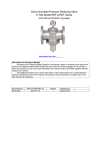
DVC TYPE 6000
INSTALLATION, OPERATION AND MAINTENANCE MANUAL
TYPE 6000
DESCRIPTION
IOM-6000-TEMPLATE-UK-050213-1
PAGE 1
DVC TYPE 6000
INSTALLATION, OPERATION AND MAINTENANCE MANUAL
1. General Precautions
a. Material Selection:
The possibility of material deterioration in service and the need for periodic inspections is
depended on the contained fluid. Carbide phase conversion to graphite, oxidation of
ferrite materials, decrease in ductility of carbon steels at low temperature (even in
applications above -29℃) are among those items. For information about corrosion, the
user is requested to take attention or consideration to determine the suitability of material
in their application.
b. Pressure-Temperature rating:
The Pressure-Temperature rating is considered for static pressure. Please refer to P & T
rating section on page 4 for working precaution. The allowable temperature is between 20℃ and 160℃ do not exceed the temperature range to avoid danger accident happen.
c. Fire safe condition:
Generally, the application of the valve shall comply with the Pressure-Temperature
rating range. If the risk of fire is major effect, user is recommended to select our
fire-safe products, which with API-607 approval. Contact to the valve distributor or
manufacturer for details.
d. Liquids with high fluid velocity:
When valves must be operated frequently on liquids with very high velocity, a
check shall be made with the valve distributor or manufacturer for appropriate
advice to minimize the possibility of seat deformation, especially when they are
highly pressurized on high-temperature line.
e. Throttling service: Valves are generally not recommended for throttling service, where
both the fluid flow and the solid particles can damage or deform the resilient seats causing
leakage. High fluid velocity or the presence of solid particles in suspension will further
reduce seat life in throttling applications.
f.
Do not disassembly when bearing pressure. Valve is not equipped with pressure access
device. User should check it by other method through its piping system.
g. Do not touch the valve surface on high temperature.
h. Not allowed for unstable fluid, otherwise specified with catogory III in Declaration of
conformity or/and in this user manual.
IOM-6000-TEMPLATE-UK-050213-1
PAGE 2
DVC TYPE 6000
INSTALLATION, OPERATION AND MAINTENANCE MANUAL
2. Product Description
2.1
3-PC SPRING LOADED CHECK VALVE
a. Valve in which the obturator movement is linear and, in the seating area, at right angle to
the direction of flow.
b. The 3-PC SPRING LOADED CHECK VALVE are used to check and control liquid media,
e.g. sewage and wastewater, where the media has solid matter volume of more than 5%,
a free flow is required for operational safety reason.
2.2
Product specification
This operation manual cover the scope of product specifications are as following
PN
Category I
Category II
63
DN 15, 20, 25
DN 32, 40, 50, 65, 80, 100
S.E.P. mean sound engineering practice, such spec. will not be labeled with CE mark.
3. Technical standard or Code applied
Items
Standards/Codes
Product Designation
prEN 12516-3
Pressure-Temperature Rating
prEN 12516-1
Testing
prEN 12266-1
Material
EN 10213-4
4. Pressure Temperature Ratings
The pressure-temperature rating of 3-PC SPRING LOADED CHECK VALVE are
determined.the choice is limited by the characteristics of the service fluid, temperature,
pressure, velocity of fluid, frequency of valves operation and sizes of valves etc, Followings
are the general rating charts for non-shock fluid service for 3-PC SPRING LOADED CHECK
VALVES distinguished by nominal pressure and seating materials.
IOM-6000-TEMPLATE-UK-050213-1
PAGE 3
DVC TYPE 6000
INSTALLATION, OPERATION AND MAINTENANCE MANUAL
PRESSURE & TEMPERATURE RATING
Temperature (℃)
Working Pressure (bar)
RT
61.2
50
58.2
100
52.2
150
47.2
160
46.0
5. Delivery Condition and Storage
Valves are deliveried with packing
Valves must store in an indoor warehouse to avoid dusts and other foreign object, do
not exposed in an open space without to put a cover over or take off the packing
under an unnecessary situation.
6. Installation
6.1
Cleaning
Even the valves was transported under a clean environment, operator must check is there
any foreign body or dusts inside the bore. If yes, clean it before installation. Operator clean
the valves by water, compression air, or steam For cleaning operation, first step is put the
valve bore perpendicular to the ground and clean, ensure all the dusts can be removed from
the bore. The second step is checking and clean all the connecting pipe bore and
connection area. No flush, rust and foreign bodies allow to avoid the blocking and leakage.
IOM-6000-TEMPLATE-UK-050213-1
PAGE 4
DVC TYPE 6000
6.2
INSTALLATION, OPERATION AND MAINTENANCE MANUAL
Valve Installation (Install to the pipeline system)
a. Direction
Follow the indication on valve body or name plate.
b. Fittings
Select the correct specification of flange to fit it to the pipeline, In comply with the valve size.
Selection of blot is according to the flange specification. Please refer to information or
technical document concerning flange end.
To tight the bolts of the flange end caps, the force must distribute on the every single bolt
evenly. The order to tight the bolts need to install symmetrically. See the drawings below.
Please see the drawings below for the order of bolts installation.
6.3
Torque Body Bolts
1/2"
3/4"
Bolts Nm
11
14
1”
1 1/4"
1 1/2"
19
22
37
2”
2 1/2"
41
46
3”
4”
48
54
Dimension
DN 15
DN 20
DN 25
DN 32
DN 40
DN 50
DN 65
DN 80
DN 100
7. Put into service
7.1
Once pipe installation is completed, Check the pipe line system to ensure the
Function of the valve.
7.2
Before delivery, valves are tested 1.5 times the allowable pressure at ambient
temperature in open position. After installation, the piping system may subject to system
tests, as condition not to exceed the above mentioned pressure.
IOM-6000-TEMPLATE-UK-050213-1
PAGE 5
DVC TYPE 6000
INSTALLATION, OPERATION AND MAINTENANCE MANUAL
8. Operation
Generally the valve have counter current stop function. Allow fluid flow through in
indicated direction, and not colose the disc to counter current.
9. Dangers of inappropriate use
Never uses the product exceed its allowed condition, such as pressure, temperature and
fluid.
In the case of any inappropriate use, the product was damage however there is no signal
occurs immediately. User shall change the product to avoid danger in the future.
10. Maintenance
10.1 Maintenance frequency
The maintenance frequency is determined upon the application of valve. User shall consider
the maintenance time interval depend on the kinds of fluid, flow velocity, operation frequency,
high-pressure and high-temperature effect etc.
10.2
Check the surface of disc is it scraped?
10.3 Assembly
For assembly process, it takes the opposite way of dismantle process. The disc must in the
close open position during assembling the body and cap.
To make sure the correct assembly, after tightening, user shall operate the valve several
MATERIALS
NO.
1
DESCRIPTION
BODY
MATERIALS
CF8M
2
END CAP
CF8M
3
DISC
AISI 316
4
SPRING
AISI 316
5
INSERT
CF8M
6
BOLT
AISI 304
7
BOLT NUT
AISI 304
8
BOLT WASHER
AISI 304
9
JOINT GASKET
PTFE
10
SCREW
AISI 304
11
CAP
AISI 316
IOM-6000-TEMPLATE-UK-050213-1
PAGE 6