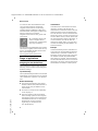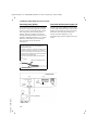
1
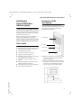
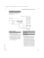
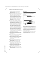
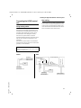
Ba Cover HC450.qxd
30.06.2006
10:50 Uhr
Seite 1
Version: 30-10-2008
english
A 3 1 0 0 8 - M1 7 9 9 - R1 0 1 - 2 - 7 6 1 9
Issued by
Gigaset Communications GmbH
Schlavenhorst 66, D-46395 Bocholt
Gigaset Communications GmbH is a trademark licensee of Siemens AG
© Gigaset Communications GmbH 2008
All rights reserved.
Subject to availability. Rights of modifications reserved.
www.gigaset.com
Gigaset
HC450
User guide
Gigaset HC450 / en / A31008-M1799-R101-2-7619 / Overview.fm / 29.09.2008
Brief overview
Brief overview
With the Gigaset HC450, the door intercom becomes an integral component of
the cordless telephone system. It supports
two-way speech using any registered
cordless telephone which means that the
house telephone no longer has to be permanently located in the entrance area.
The Gigaset HC450 door intercom is suitable for practically all single-family residences, including those that only have
a bell.
Main features
u Two-way speech with callers to the
u
u
u
u
u
u
Version 4, 16.09.2005
u
door using the cordless telephone –
including handsfree
Intuitive operation via the handset's
softkeys (open door, activate entry
light)
Easy configuration using the menu on
the handset
Forwarding to external numbers
Ease of installation and registration
with the Gigaset system
Replacement of the old bell button
with the door intercom – the existing
cabling is generally adequate for
installation
Support for existing bell and standard
door openers
Configuration options for the second
bell key (separate door call to specific
handset, activation of entry lighting,
same function as first bell key)
Gigaset Home Control
"Gigaset Home Control" is a standard that
allows you to control
u household appliances
u lights and blinds
u alarm systems
u heating and air conditioning systems
and
u door intercoms such as the
Gigaset HC450
from a Gigaset cordless telephone.
The full functionality of the HC450 door
intercom (opening the door from the
handset, forwarding calls to an external
number and configuring the system) is
available in conjunction with Gigaset cordless telephones that support "Gigaset
Home Control". A list of all compatible
devices can be found in the appendix and
on the Internet at
www.gigaset.com/customercare.
If you are operating the door intercom
with a standard DECT handset that is not
fully compatible and only supports the
GAP standard, only the "intercom" function is possible.
(GDECT / GAP is the transmission protocol
for cordless phones. This allows handsets
of one manufacturer to be operated on
the base station of a different manufacturer. In this case, however, operation is
restricted to the telephones' basic functions.)
1
Gigaset HC450 / en / A31008-M1799-R101-2-7619 / Overview.fm / 29.09.2008
Brief overview
In common with the HC450 door intercom, all other products certified for
"Gigaset Home Control" can be easily
installed without additional cables and
networked with the Gigaset cordless telephone at the push of a button.
"Gigaset Home Control" thus grows with
your needs.
All compatible devices feature the "Gigaset Home
Control" logo, making them
very easy to identify.
Call diversion
You will find more detailed and up-to-date
information together with sources of supply for compatible products on the Internet at the following link:
www.gigaset-home-control.com
Example:
Range of applications
Assigning the two doorbell keys
The HC450 door intercom has two doorbell keys, each of which can be assigned
different settings.
Top doorbell key:
The top doorbell key activates a connected
external bell. At the same time, an internal
call is initiated to a specific or to all handsets.
Bottom doorbell key:
Version 4, 16.09.2005
u The bottom doorbell key can initiate
another internal call (other handset or
other ringer tone) in addition to the
external bell.
u Its function can also be set identically
to the top key or
u The entry lighting can be activated
when the key is pressed. This requires
the lighting system to be connected to
the HC450 control unit. If the bottom
doorbell key is being used as a
"lights key", it cannot function
as a "doorbell key".
2
If call diversion is activated for the door
intercom, the door call will then be
diverted to the external number. The call
diversion relates to the top doorbell key.
The call diversion can be controlled in different ways: If the occupier is at home he/
she sets "Status: Home", which means that
the internal handset will be called first. If
no-one answers, the call will then be
diverted. If "Status: Away" is set, the door
call will immediately be forwarded to an
external number.
In the Smith family's house, handset no. 1
rings when the top doorbell key labelled
"Smith family" is pressed. Handset no. 2
belonging to the son will only ring when
the bottom doorbell key labelled "Matthew Smith" is pressed. The Smith family
has activated call diversion. If no-one from
the family is at home, then the call will be
forwarded to the father's mobile phone.
Gigaset HC450 / en / A31008-M1799-R101-2-7619 / Overview.fm / 29.09.2008
Brief overview
Door opener, bell and entry lighting
Door light:
A light circuit (e.g. the entry
lighting) can be switched on
from the handset and if applicable via the bottom bell key
for between 1 and 90 seconds
or also operated in pulse mode.
The connection to the floating
contact (230 V, 10 A) must be
undertaken by a qualified electrician.
The illustration below shows the cabling
with an existing doorbell (before) and the
cabling following installation of the
HC450 door intercom and HC450 control
unit (after).
The following devices, which are not
among the items supplied, can be connected to the HC450 and operated:
Door opener:
The door can be opened from
the Gigaset handset or, in the
case of a forwarded call, from
a remote location. To do this, a
standard door opener must be
connected (not supplied). The
voltage pulse (12 V alternating
voltage) for opening the door
is supplied by the HC450.
Bell:
An existing bell will be connected to the HC450.
After
Door intercom
ETS
Power
supply unit
Bell trans.
Bell transformer
(optional)
Bell
Control unit
Control unit
Pushbutton
Light
Actuator
Doorbell
Door opener
Before
Bell
Bell trans.
Door opener
Version 4, 16.09.2005
Bell transformer
3
Gigaset HC450 / en / A31008-M1799-R101-2-7619 / HC450IVZ.fm / 08.10.2008
Contents
Contents
Brief overview . . . . . . . . . . . . . . . . . . . . . . . . . . . . . . . . . . . . . . . . . . . . . . . . . . 1
Gigaset Home Control . . . . . . . . . . . . . . . . . . . . . . . . . . . . . . . . . . . . . . . . . . . . . . . . . . . . 1
Range of applications . . . . . . . . . . . . . . . . . . . . . . . . . . . . . . . . . . . . . . . . . . . . . . . . . . . . . 2
Safety precautions . . . . . . . . . . . . . . . . . . . . . . . . . . . . . . . . . . . . . . . . . . . . . . 5
Installing the Gigaset HC450 door intercom system . . . . . . . . . . . . . . . . . . . 7
Pack contents . . . . . . . . . . . . . . . . . . . . . . . . . . . . . . . . . . . . . . . . . . . . . . . . . . . . . . . . . . . 7
Mounting the HC450 door intercom . . . . . . . . . . . . . . . . . . . . . . . . . . . . . . . . . . . . . . . . . 7
Mounting the HC450 control unit . . . . . . . . . . . . . . . . . . . . . . . . . . . . . . . . . . . . . . . . . . . 9
Connecting the HC450 control unit . . . . . . . . . . . . . . . . . . . . . . . . . . . . . . . . . . . . . . . . . 11
Setting up the Gigaset HC450 door intercom system . . . . . . . . . . . . . . . . . 13
Registering with the base station . . . . . . . . . . . . . . . . . . . . . . . . . . . . . . . . . . . . . . . . . . 13
Setting functions . . . . . . . . . . . . . . . . . . . . . . . . . . . . . . . . . . . . . . . . . . . . . . . . . . . . . . . 13
Operating the Gigaset HC450 door intercom using the handset . . . . . . . 18
Incoming call from the door intercom . . . . . . . . . . . . . . . . . . . . . . . . . . . . . . . . . . . . . . . 18
Calling the door intercom
from an internal user . . . . . . . . . . . . . . . . . . . . . . . . . . . . . . . . . . . . . . . . . . . . . . . . . . . . 18
Operation with automatic
call diversion . . . . . . . . . . . . . . . . . . . . . . . . . . . . . . . . . . . . . . . . . . . . . . . . . . . . . . . . . . . 19
Menu tree . . . . . . . . . . . . . . . . . . . . . . . . . . . . . . . . . . . . . . . . . . . . . . . . . . . . 21
Appendix . . . . . . . . . . . . . . . . . . . . . . . . . . . . . . . . . . . . . . . . . . . . . . . . . . . . . 23
Cleaning . . . . . . . . . . . . . . . . . . . . . . . . . . . . . . . . . . . . . . . . . . . . . . . . . . . . . . . . . . . . . .
Questions and answers . . . . . . . . . . . . . . . . . . . . . . . . . . . . . . . . . . . . . . . . . . . . . . . . . .
Gigaset cordless telephones
compatible with the HC450 . . . . . . . . . . . . . . . . . . . . . . . . . . . . . . . . . . . . . . . . . . . . . . .
Service (Customer Care) . . . . . . . . . . . . . . . . . . . . . . . . . . . . . . . . . . . . . . . . . . . . . . . . .
Authorisation . . . . . . . . . . . . . . . . . . . . . . . . . . . . . . . . . . . . . . . . . . . . . . . . . . . . . . . . . .
Guarantee Certificate
United Kingdom . . . . . . . . . . . . . . . . . . . . . . . . . . . . . . . . . . . . . . . . . . . . . . . . . . . . . . . .
Guarantee Certificate
Ireland . . . . . . . . . . . . . . . . . . . . . . . . . . . . . . . . . . . . . . . . . . . . . . . . . . . . . . . . . . . . . . . .
Technical Data . . . . . . . . . . . . . . . . . . . . . . . . . . . . . . . . . . . . . . . . . . . . . . . . . . . . . . . . .
23
23
24
24
25
25
26
27
Version 4, 16.09.2005
Index . . . . . . . . . . . . . . . . . . . . . . . . . . . . . . . . . . . . . . . . . . . . . . . . . . . . . . . . . 28
4
Gigaset HC450 / en / A31008-M1799-R101-2-7619 / Security.fm / 18.09.2008
Safety precautions
Safety precautions
Caution:
Read the safety precautions and the manual before use.
Explain their contents to your children as well as the potential hazards associated with using the
telephone.
u Only use the mains adapter supplied, as indicated on the underside of the control unit.
This adapter is only intended for use on the Gigaset HC450 and must not be connected to other devices.
Make sure that the mains adapter is accessible at all times.
Do not continue to use broken plugs or plug-in power supply units with broken housings as they pose a risk of electric shock. Have these parts replaced with genuine spare
parts without delay.
u The housing of the HC450 control unit and door intercom must not be opened. Unau-
thorised opening of the housing and improper repairs may endanger the user and will
invalidate the warranty.
u The control unit is designed for indoor operation only. Lay the cables so that nobody
can walk on or trip over them.
u The control unit includes a radio module in accordance with the DECT standard. The
operation of medical appliances may be affected. Be aware of the technical conditions
in your respective environment, e.g. doctor's surgery.
u The module must not be installed during a thunderstorm, nor should any cable connec-
tions be plugged in or unplugged, as to do so would expose you to the risk of electric
shock.
u Do not allow fluids to penetrate the HC450 control unit and door intercom as this could
result in electric shocks or short circuits.
u Do not use your telephone in environments with a potential explosion hazard, e.g. auto
paint shops.
u If you give your Gigaset HC450 door intercom to someone else, make sure you also give
them the manual.
u The entry light may only be installed by a qualified electrician. Please observe the
respective national regulations for the installation of electrical and telecommunications systems.
u Only equipment supplying safety extra-low voltage (SELV) and complying with
Version 4, 16.09.2005
EN 60950 may be connected to the control unit (actuator output).
5
Gigaset HC450 / en / A31008-M1799-R101-2-7619 / Security.fm / 18.09.2008
Safety precautions
All electrical and electronic products should be disposed of separately from the
municipal waste stream via designated collection facilities appointed by the
government or the local authorities.
This crossed-out wheeled bin symbol on the product means the product is covered by the European Directive 2002/96/EC.
The correct disposal and separate collection of your old appliance will help prevent potential negative consequences for the environment and human health.
It is a precondition for reuse and recycling of used electrical and electronic
equipment.
For more detailed information about disposal of your old appliance, please contact your city office, waste disposal service or the shop where you purchased the
product.
Note:
Version 4, 16.09.2005
Not all of the functions described in this manual are available in all countries.
6
Gigaset HC450 / en / A31008-M1799-R101-2-7619 / Starting.fm / 08.10.2008
Installing the Gigaset HC450 door intercom system
Installing the
Gigaset HC450 door
intercom system
Installation of the HC450 door intercom
system does not require additional cables
to be laid if a doorbell with sound effect is
already present. You replace the existing
doorbell key in this case.
Begin by checking that you have all the
components required for mounting.
Please read the entire chapter on installation carefully before you commence.
Mounting the HC450
door intercom
The HC450 door intercom generally
replaces the existing doorbell. It is suitable
for mounting outdoors and features
weatherproof protection.
Loudspeaker
Pack contents
Top key
u 1 control unit with cover
u 4 plugs and mounting screws for fixing
Bottom key
u
u
u
u
u
u
u
u
the control unit and door intercom
1 HC450 door intercom
1 frame for surface mounting
1 plug-in power supply unit
2 hexagon socket screws for fixing the
door intercom to the frame
1 Allen key for the hexagon socket
screws
2 clamping plugs for connecting the
cables to the door intercom
2 doorbell key covers and nameplates
2 thermal shrinkage tubes
Microphone
u Make sure that there are no power sup-
ply lines, cables or the like near the
mounting location.
u Select the attachment and mounting
location so that there is a minimum distance of 10 cm between the microphone and the closest wall surface.
min. 10 cm
Version 4, 16.09.2005
min. 10 cm
7
Gigaset HC450 / en / A31008-M1799-R101-2-7619 / Starting.fm / 08.10.2008
Installing the Gigaset HC450 door intercom system
Surface mounting
u Remove the bell button if there is one
and unscrew the cables. Fit the frame
over the cable outlet. Next screw one of
the enclosed green clamping plugs to
the existing 2-core bell cable (polarity is
not relevant here) and insert it in the
jack with the ETS symbol (green jack).
Caution:
If you are using the existing bell cable, the
doorbell system must be set to zero potential
prior to installation.
Caution:
Cables must not be connected or disconnected
during a thunderstorm.
u Hang the door intercom at the top of
Version 4, 16.09.2005
the frame (45 degree angle, see illustration on right) and lower it against
the wall. Fix the door intercom using
the two enclosed hexagon socket
screws.
8
Gigaset HC450 / en / A31008-M1799-R101-2-7619 / Starting.fm / 08.10.2008
Installing the Gigaset HC450 door intercom system
Connecting a door opener (optional)
The door opener is connected to the
appropriate jack of the door intercom
using a 2-core cable and the blue
clamping plug.
Door intercom
Control unit
Light
Actuator
ETS
Cable plug
Door opener
Labelling nameplates
Mounting the HC450 control unit
u Label the enclosed nameplates using a
Version 4, 16.09.2005
waterproof pen. Insert them in the
recesses in the doorbell keys.
u Position the doorbell key cover on the
doorbell key from above and then apply
gentle pressure at the top and bottom.
u Replacing nameplates: Insert a small
screwdriver at an angle in the narrow
notch on either side of the doorbell key
cover. Carefully lever off the cover.
Remove the nameplate.
Requirements
The following requirements for mounting
must be fulfilled:
u The HC450 control unit contains a
DECT radio module. This module must
be mounted within the base station's
radio range (typically around 30 m
indoors). Check the range using the
handset before fixing the control unit.
If a connection from a DECT handset to
the DECT base station is possible at the
designated location (field strength display shows at least one bar or a call of
long duration is possible with satisfactory quality), you can mount the control unit here. If there is no connection
to the base station at the designated
mounting location, the range can be
9
Gigaset HC450 / en / A31008-M1799-R101-2-7619 / Starting.fm / 08.10.2008
Installing the Gigaset HC450 door intercom system
u
u
u
u
u
u
u
Version 4, 16.09.2005
u
u
10
extended by means of a repeater
placed between the base station
and control unit.
Mount the HC450 control unit at a suitable location along the junction wire
between the bell button and bell.
It is recommended that you mount the
unit near the bell transformer. This is
normally located in the fuse box. Any
adjustment required to the fuse box
must be undertaken by a qualified
electrician.
To ensure that a suitable mounting
location is selected, familiarise yourself
with the location of the cabling beforehand. Watch out for the cabling
between the bell button, the bell transformer and the bell. Lay the cables so
that nobody can walk on or trip over
them. Before finally mounting the
control unit, check the placement of
the unit with temporary cabling by performing a function test (control unit
can register with the base station, stable operation possible with adequate
connection quality from the handset to
the HC450 door intercom).
You should also refer to the mounting
instructions for the HC450 door intercom (see p. 7).
The control unit must not be installed
in a fuse box or metal housing.
The control unit must not be installed
near air conditioning systems, in areas
with strong sunlight or in dusty
environments.
The control unit must be protected
from the direct influence of water
and chemicals.
Areas with strong magnetic fields
(transformers, electric motors, highvoltage lines) must be avoided.
Cables must not be connected or disconnected or the HC450 control unit
installed during a thunderstorm.
Watch out for electrical, water or gas
lines in the wall if mounting the control
unit on the wall.
Mounting
If necessary, loosen the screws from the
casing. Pull the cover downwards to
remove it.
Mounting hole
LED
Clip-on cover
Button
Mounting hole
Casing screw
Strain relief
Mark the positions of the two drill holes on
the wall. Drill two holes suitable for 6 mm
wall plugs. Screw the upper screw into the
wall plug and mount the casing by fixing
the upper mounting hole onto the screw.
Screw the casing into place using the
lower mounting hole.
For laying the cables, a multi-core communications cable is recommended with a
wire profile of 0.6 mm.
Gigaset HC450 / en / A31008-M1799-R101-2-7619 / Starting.fm / 08.10.2008
Installing the Gigaset HC450 door intercom system
Connecting the HC450 control
unit
New cabling
Connect the 2-core cable of the door intercom to the terminals marked "ETS" in the
control unit (see illustration below). Connect the bell transformer/bell to the "Actuator" terminals in the control unit.
Using existing cables
Disconnect the existing connection
between the doorbell and the bell transformer/bell at an appropriate location, if
possible near where the control unit is
mounted (see next diagram on left).
Connect the open ends for the bell
transformer/bell with the "Actuator" terminals in the control unit (polarity is not
relevant).
Connect the open ends for the doorbell
with the "ETS" terminals in the control unit
(polarity is not relevant).
Caution:
Cables must not be connected or disconnected
during a thunderstorm.
After
Door intercom
ETS
Power
supply unit
Bell trans.
Bell transformer
(optional)
Bell
Control unit
Control unit
Pushbutton
Light
Actuator
Doorbell
Door opener
Before
Bell
Bell trans.
Door opener
Version 4, 16.09.2005
Bell transformer
11
Gigaset HC450 / en / A31008-M1799-R101-2-7619 / Starting.fm / 08.10.2008
Installing the Gigaset HC450 door intercom system
Connecting entry lighting
Connection with the power supply unit
If you want to use the bottom doorbell key
to switch on the entry lighting, the light
source must be connected to the control
unit using two cores (see illustration
below). The entry lighting can also be
switched on/off by means of a switch connected in parallel (see sketch, e.g. motion
detector). Alternatively, a sensor input
from a timing circuit can also be
connected.
Connect the mains adapter with the plug
on the right-hand side of the control unit.
Slide the cover back into the main casing.
Screw the cover into place using the
casing screw (see diagram p. 10).
Insert the plug-in power supply unit into a
socket.
Caution:
The entry light may only be installed by a
qualified electrician.
Stranded conductors must not be used for the
connection and the insulation on the leads
must not be stripped by more than 6 mm. The
shrinkage tubes supplied must be pulled over
the two wires (see diagram).
Secure the connection cable with the strain
relief.
≤ 6 mm
Thermal shrinkage tubes
Control unit
Light
Strain
relief
Pushbutton
Actuator
Version 4, 16.09.2005
Entry lighting
230 V mains
12
ETS
Gigaset HC450 / en / A31008-M1799-R101-2-7619 / TFE_Setting.fm / 08.10.2008
Version 4, 16.09.2005
Setting up the Gigaset HC450 door intercom system
Setting up the
Gigaset HC450 door
intercom system
u Following successful registration,
Once you have installed your HC450 door
intercom system, you can set up the door
intercom at your convenience using a
compatible handset. Before you can do
this, however, you must register the door
intercom system with the base station.
Note:
Registering with the base station
Setting functions
Make sure that the control unit is connected to a power supply. If the LED on the
HC450 control unit is flashing, it means
that it is not yet connected with the base
station.
u Set the 4-digit system PIN of your base
station to "0000" if necessary (refer to
the manual for your telephone).
u Press the registration/paging key on the
base station for approx. 3 seconds. The
registration/paging key is located on
the right beside the charging cradle.
u Go over to the control unit and press
the button on the control unit with a
thin object such as a paper clip within
20 seconds (see illustration on p. 11).
The LED on the control unit will light up
continuously once it has been registered (the LED will return to flashing
when a call is underway between the
door intercom and base station). If registration does not take place despite a
number of attempts, reduce the distance between the base station and
control unit (the base station can be
disconnected from the telephone network to do this) and/or briefly disconnect the control unit from the power
supply before commencing registration.
Starting programming
"Intercom" will appear in the list of internal users. This preset name can be
changed via the handsets (refer to the
user guide for the handset).
Change the system PIN of the base station
once more (refer to the manual for your telephone). This ensures, among other things,
that only designated handsets can be registered with the base station.
Call up the menu for the door intercom
settings. This initial programming step is
always the same for all functions to be set.
Note:
The menu for changing the display language is
called up automatically during startup
(see p. 13).
u
c
Initiate an internal call and
select the internal user
"Intercom".
Press the talk key.
¨
~
Press the display key.
Enter the 4-digit system PIN of
the door intercom if the PIN
has been changed from the
delivery version (0000) and
press §OK§.
You are now in the menu in which you can
make settings for the door intercom.
Changing the display language
You can view the display texts in different
languages. The languages available
include English, German, Italian, Dutch
and French.
Call up the menu for the settings
(see p. 13):
13
Gigaset HC450 / en / A31008-M1799-R101-2-7619 / TFE_Setting.fm / 08.10.2008
Setting up the Gigaset HC450 door intercom system
q ¢ Language ¢ §OK§
The current setting is displayed.
English
Select the desired language,
for example "English" and
press §OK§.
a
Press and hold (return to
idle status).
Changing the PIN of the door intercom
The door intercom allows you to assign a
custom PIN to protect its settings against
unauthorised access. You can change the
4-digit PIN (delivery version 0000) to a
4-digit PIN known only to you.
Call up the menu for the settings
(see p. 13):
q ¢ Door PIN ¢ §OK§
~
Enter a 4-digit PIN and
press §OK§. The entry is saved.
a
Press and hold (return to
idle status).
Note:
To prevent misuse, we recommend assigning a
separate PIN each for the door intercom and
the base station.
The door can only be opened from an external
telephone (see p. 19) by entering a separate
PIN other than 0000 for the door intercom.
Making settings for the top
doorbell key
Version 4, 16.09.2005
You can set a specific internal call destination (handset) and ringer tone for the top
doorbell key of the door intercom. You can
also set the doorbell key to call all registered handsets.
Setting an internal call destination and
ringer tone
Call up the menu for the settings
(see p. 13):
q ¢ Upper Door Key ¢ §OK§
alternatively ...
s ¢ Internal Dest. ¢ §OK§
A list is displayed. It contains the entry
"Call All" and the internal names of all registered handsets.
The current setting is displayed.
Select an internal user (e.g. "Anna") and
confirm:
q ¢ Anna ¢ §OK§
If "Call All" is set, an incoming call from the
door intercom will be forwarded to all
internal users.
or ...
s ¢ Ringer Tone ¢ §OK§
The current setting is displayed.
q
Select the desired ringer tone
(call melody 1-6) or special
"GHC melody".
§Save§
Press the display key.
... continue with
a
Press and hold (return to
idle status).
Note:
If "Call All" is set and different handset types are
being used, the call melodies of the individual
handsets can differ.
Making settings for the bottom
doorbell key
You have four options here:
1. "As Upper Key" setting (as for first door
call): The function of the two keys is
then identical.
2. "Second Door Call": You can select another internal user (and different tone
dialling if necessary).
14
Gigaset HC450 / en / A31008-M1799-R101-2-7619 / TFE_Setting.fm / 08.10.2008
Setting up the Gigaset HC450 door intercom system
3. "Light": You can use the doorbell key to
control the entry lighting as an alternative to the "Door Call". The lighting system must be connected to the control
unit for this purpose.
4. "No Function".
Call up the menu for the settings
(see p. 13):
q ¢ Lower Door Key ¢ §OK§
The current setting is displayed.
Select the mode for the bottom key:
"Second Door Call", "Light" or "No Function".
§Save§
Press the display key.
... continue with
a
Press and hold (return to
idle status).
Proceed as described in the section
"Making settings for the top doorbell key"
(see p. 14) to set the internal call
destination and ringer tone.
The only difference is: In the menu for the
door intercom settings select the entry
"Low. Key Setting" instead of "Upper Door
Key".
Setting up a call diversion to an
external number
You can set up the call diversion using the
following programming steps.
Caution:
Version 4, 16.09.2005
Note that you can very easily activate or deactivate the call diversion from your handset.
When you are at home, set the door intercom
to "Status: Home". The incoming calls from the
door intercom will then be sent to your internal handset. When you are leaving the house,
set the door intercom to "Status: Away". The
incoming calls will then immediately be routed
to your external diversion destination. Refer to
the chapter "Operation with automatic call
diversion" (p. 19) to find out how to make the
switch.
The external call diversion destination relates
only to the top doorbell key.
Setting the destination for automatic call
diversion to an external number
You can divert incoming calls from the
door intercom to an external number. To
do this, you must first enter the destination number.
Call up the menu for the settings
(see p. 13).
q ¢ Diversion No. ¢ §OK§
~
Enter the number (max. 20
characters) for the external
call diversion and press §OK§.
The setting is saved.
a
Press and hold (return to
idle status).
Caution:
Don't forget the zero for a trunk line if applicable.
If you do not enter a number for the external
call forwarding, automatic call diversion to an
external number will be switched off.
Activating/deactivating automatic call
diversion to an external number
You can only activate the "Automatic Call
Diversion" function if you have previously
entered a diversion destination
(see p. 15).
Call up the menu for the settings
(see p. 13).
q ¢ Diversion ¢ §OK§
The current setting is displayed.
r
Activate or deactivate automatic call diversion.
§Save§
Press the display key.
... continue with
a
Press and hold (return to
idle status).
15
Gigaset HC450 / en / A31008-M1799-R101-2-7619 / TFE_Setting.fm / 08.10.2008
Setting up the Gigaset HC450 door intercom system
Setting the duration of the door light
The following settings can be selected:
Pulse, 1, 2, 3, 10, 20, 30, 40, 50, 60, 70,
80 and 90 seconds.
Call up the menu for the settings
(see p. 13):
q ¢ Timer ¢ §OK§ ¢ Door Light ¢ §OK§
The current setting is displayed.
r
Select the desired duration
(pulse, 1 s, 2 s, 3 s, 10 s ...
90 s).
§Save§
Press the display key.
... continue with
a
Press and hold (return to
idle status).
Setting the duration of the bell
You can set how long the bell at the door
intercom should sound when the doorbell
key is pressed. The following settings can
be selected: pulse, 1, 2 or 3 seconds.
Call up the menu for the settings
(see p. 13):
q ¢ Timer ¢ §OK§ ¢ Door Bell ¢ §OK§
The current setting is displayed.
r
Select the desired duration
(pulse, 1, 2 or 3 s).
§Save§
Press the display key.
... continue with
a
Press and hold (return to
idle status).
Version 4, 16.09.2005
Setting the internal and external call
time for incoming calls from the door
intercom
You can set how long the handset should
ring for an incoming call from the door
intercom to an internal user and for a call
diversion to an external user. The following settings can be selected: no int. Ringing,
10, 20, 30 or 60 seconds.
16
Call up the menu for the settings
(see p. 13):
q ¢ Timer ¢ §OK§
alternatively ...
q ¢ Int. Door Call ¢ §OK§
or ...
q ¢ Ext. Door Call ¢ §OK§
The current setting is displayed.
r
Select the desired time (no int.
Ringing, 10, 20, 30 or 60 s).
§Save§
Press the display key.
... continue with
a
Press and hold (return to
idle status).
Setting the external call duration for an
incoming call from the door intercom
If a call diversion is set up to an external
user, you can restrict the call duration for
an incoming call from the door intercom.
You can define how long a connection
can last.
The following settings can be selected: 30,
60, 90 or 120 seconds.
Call up the menu for the settings
(see p. 13):
q ¢ Timer ¢ §OK§
¢ Ext. Call Dur. ¢ §OK§
The current setting is displayed.
r
Select the desired time
(30, 60, 90 or 120 s).
§Save§
Press the display key.
... continue with
a
Press and hold (return to
idle status).
Gigaset HC450 / en / A31008-M1799-R101-2-7619 / TFE_Setting.fm / 08.10.2008
Setting up the Gigaset HC450 door intercom system
Setting the volume of the external
loudspeaker
You can set the volume of the external
loudspeaker at the door intercom to nine
different levels.
Call up the menu for the settings
(see p. 13):
q ¢ Volume ¢ §OK§
r
Select the desired volume
for the external loudspeaker
(1-9).
Press the display key.
... continue with
a
Press and hold (return to
idle status).
§Save§
Note:
Version 4, 16.09.2005
The voice connection between the handset
and door intercom is activated during the setting process. This allows you to check the volume of the external loudspeaker directly.
17
Gigaset HC450 / en / A31008-M1799-R101-2-7619 / TFE_MT.fm / 08.10.2008
Operating the Gigaset HC450 door intercom using the handset
Operating the
Gigaset HC450 door
intercom using the handset
Operation of the HC450 door intercom is
largely identical for all handsets. It is
described in this manual using the Gigaset
S45 (high-feature handset). Some aspects
of operation will differ between the standard handset and the high-feature handset.
Incoming call from the door
intercom
Version 4, 16.09.2005
When a call comes in from the door intercom (the bell will ring), either all handsets
or just a specific handset will be called
depending on the setting. If a call diversion from the door intercom is set up to an
external number, the call will be diverted
to the set number.
a
Press the end call key to reject
the call.
or ...
c/d
Press the talk or loudspeaker
key.
You are connected with the door intercom. "Intercom" appears in the display.
alternatively ...
§Op.Door§
Press the display key to activate the door opener. The
door opener is activated.
or ...
§Light§
Press the display key to switch
on the entry lighting.
a
Press the end call key.
18
Note:
The caller to the door can switch on the entry
lighting, if set, using the bottom door key
(see p. 12).
The following features are not available
for an incoming call from the door
intercom:
u Conducting a conversation
u Calling back from a conversation with
the door intercom
u Toggling a caller at the door intercom
u Conducting a conference call with a
user at the door intercom
u Diverting or forwarding an incoming
call from the door intercom
Calling the door intercom
from an internal user
You can call the door intercom internally
and operate it even if the bell did not ring
first. To do this, you must first select the
internal user "Intercom" at the handset.
Select the internal user "Intercom".
u
Open the list of internal users.
q ¢ Intercom ¢ c
¨
Press the display key.
q ¢ Connect to Door ¢ §OK§
alternatively...
§Op.Door§
Press the display key to activate the door opener. The
door opener is activated.
or ...
§Light§
Press the display key to switch
on the entry lighting.
or ...
a
Press the end call key.
Gigaset HC450 / en / A31008-M1799-R101-2-7619 / TFE_MT.fm / 08.10.2008
Operating the Gigaset HC450 door intercom using the handset
Operation with automatic
call diversion
When a call is diverted, all the functions
can also be used remotely from a mobile
phone, for example to ask the postman to
leave a parcel with a neighbour.
Switching between "Status: Home"
and "Status: Away"
If you have entered an external number
for call forwarding, you can switch
between "Status: Home" and "Status: Away".
The call diversion only ever relates to the
top doorbell key.
u With "Status: Home", the defined internal user will be called when a call
comes in from the door intercom. If the
"Automatic Call Diversion" function is
activated and the internal user does not
answer the incoming call within the set
time (see "Setting the internal and
external call time for incoming calls
from the door intercom", p. 16), the
incoming call will be diverted to the
defined external number.
u With "Status: Away", the call coming in
from the door intercom will be diverted
to the defined external number.
Calling the door intercom internally:
u
Initiate an internal call and
select the internal user
"Intercom".
§Edit§
Press the display key if necessary to change the mode.
a
Press and hold (return to
idle status).
Version 4, 16.09.2005
Note:
The incoming call cannot be diverted to a further telephone if the external number is
engaged when the call comes in from the door
intercom or if an answering machine answers.
The door intercom will not, however, be connected with the trunk line in this case.
Answering a diverted call at an
external telephone
When you answer the call you will hear a
recorded announcement that is repeated
at regular intervals. You now have the
option of accepting the call or terminating
the process:
1
Press the 1 key to accept the
call.
#
Press the hash key # to end
the call.
The recorded announcement does not
offer the option to open the door, however this option will be available to you if
there is a door opener connected to your
door intercom.
O
Press the 9 key to open the
door.
~
Enter the 4-digit PIN.
Note:
It is only possible to open the door from an
external telephone if a separate PIN other than
0000 has been set up beforehand for the door
intercom (see p. 14).
Warning:
If you want to use the door opening function
from outside, the front door cannot be locked.
Please note the conditions of your insurance
policy relating to break-ins.
If you enter the PIN correctly, you will hear
a recorded announcement and the door
will be opened. The voice connection will
still be active; you can terminate it by
pressing the hash key #.
If you did not enter the PIN correctly, you
will hear a recorded announcement:
"Enter PIN". You can then either re-enter
the PIN or re-establish the voice connection with the caller by pressing the star
key *. To terminate the voice connection, press the hash key #.
If the conversation lasts longer than the
set external call duration, a recorded
announcement will sound 10 seconds
19
Gigaset HC450 / en / A31008-M1799-R101-2-7619 / TFE_MT.fm / 08.10.2008
Operating the Gigaset HC450 door intercom using the handset
before the connection is due to be terminated. You can prolong the connection by
pressing the 1 key.
If the set external call duration is exceeded
once more, a recorded announcement will
sound again 10 seconds before the connection is due to be terminated. The connection will be automatically terminated if
you do not press the 1 key with approx. 5
seconds.
Terminating the process:
#
Note:
Press the hash key.
Version 4, 16.09.2005
The door intercom automatically disconnects
the line after the set time and thereby frees the
line again.
20
Gigaset HC450 / en / A31008-M1799-R101-2-7619 / Menuetree.fm / 08.10.2008
Menu tree
Menu tree
In the Settings menu of the Gigaset HC450:
Connect to Door
(p. 18)
Diversion No.
(p. 15)
Diversion
(p. 15)
Volume
Volume: 1
...
Volume: 9
(p. 17)
Upper Door Key
Internal Dest.
Call All
(p. 14)
INT 1
...
INT 6
(p. 13)
Ringer Tone
Melody 1
...
Melody 6
GHC-Melody **
(p. 14)
No Function
(p. 14)
Lower Door Key
As Upper Key
Second Door Call
Light
Low. Key Setting *
Language
Call All
(p. 14)
INT 1
...
INT 6
(p. 13)
Ringer Tone
Melody 1
...
Melody 6
GHC-Melody **
(p. 14)
Deutsch
(p. 13)
Internal Dest.
English
Francais
Italiano
Nederlands
Dansk
Suomi
Norsk
Svenska
Espanol
Version 4, 16.09.2005
Portugues
*)
This setting will only appear if the "Second Door Call" setting is activated in the
"Upper Door Key" menu.
**) not available on all Gigaset phones
21
Gigaset HC450 / en / A31008-M1799-R101-2-7619 / Menuetree.fm / 08.10.2008
Menu tree
Version 4, 16.09.2005
Timer
22
Door Light
impulse
1 second
...
90 second
(p. 16)
Door Bell
impulse
1 second
...
3 second
(p. 16)
Int. Door Call
no int. Ringing
10 second
...
60 second
(p. 16)
Ext. Door Call
30 second
...
120 second
(p. 16)
Ext. Call Dur.
30 second
...
120 second
(p. 16)
Gigaset HC450 / en / A31008-M1799-R101-2-7619 / Appendix.fm / 08.10.2008
Appendix
Appendix
Cleaning
¤ Wipe the HC450 door intercom with a
damp cloth (do not use solvent) or an
antistatic cloth.
Never use a dry cloth. This can cause
static.
Questions and answers
If you have any queries about the use of
your HC450 door intercom, contact us at
www.gigaset.com/customercare
24/7. The table below contains a list of
common problems and possible solutions.
Control unit
No function
No power supply.
¥
Check the power supply.
Door opener not working
– no switching noise
Door opener is not correctly connected or does
not conform to the specifications.
Check the installation. Check whether the
door opener is within the supported specification.
¥
Door opener not working
– switching noise, but door not opening.
Door opener is not within the specification or
not correctly installed mechanically.
Check whether the door opener is within
the supported specification or check the
installation of the door opener (if necessary
adjust).
¥
HC450 door intercom
No function, no keys lighting up
No operating current.
¥
Check the installation, check whether the
connections at the terminals are in the correct connection sequence.
Door intercom working (bell working), but
not signalling at the mobile phones.
1. Control unit is not registered with the base
station (control unit LED flashing).
Register the control unit.
¥
2. Control unit has been registered but is
dropping the connection (LED flashing).
Reduce the distance between the base
station and the control unit. Install a
repeater if necessary.
¥
Bell not signalling at the mobile phones,
even through the control unit
has a connection to the base station (control unit LED lighting up continuously).
1. no int. Ringing is set.
Select a value between 10 and
60 seconds.
¥
2. Call forwarding activated
(display showing "line in use").
Select "Status: Home".
¥
3. Handsets outside of range or switched off,
specifically set handset deregistered or
switched off.
Bring the handsets within the base station's range, switch on or charge the
handsets.
Select another handset for signalling or
switch over to "Signal to All Handsets".
¥
¥
If the problem cannot be rectified through
the measures specified, you can reset the
control unit's factory settings. To reset the
factory settings, press the button on the
control unit with a thin object such as a
paper clip for 35 seconds (see diagram on
p. 10).
Version 4, 16.09.2005
Please note:
Any settings you have made will be lost when
you reset the factory settings. You will have to
reregister the control unit, see p. 13.
23
Gigaset HC450 / en / A31008-M1799-R101-2-7619 / Appendix.fm / 08.10.2008
Appendix
Gigaset cordless telephones
compatible with the HC450
Compatible base stations
Gigaset SX440/SX445isdn
Gigaset SX450/SX450isdn
Gigaset E450/E455*
Gigaset E450 SIM/E455 SIM*
Gigaset S440/S445*
Gigaset S450/S455*
Gigaset S450 SIM/S455 SIM*
Gigaset S450 IP*
Gigaset S645
Gigaset SL440
Gigaset SL550/SL555*
Gigaset SL560/SL565*
Gigaset SL370/SL375*
Gigaset S670/S675*
Gigaset S675 IP*
Gigaset C470/C475*
Gigaset C470 IP/C475 IP*
Compatible high-feature handsets
Gigaset E45*
Gigaset S1/S1 colour
Gigaset S44
Gigaset S45*
Gigaset SL1/SL1 colour
Gigaset SL55*
Gigaset SL56*
Gigaset SL74
Gigaset SL37H*
Gigaset S67H*
Version 4, 16.09.2005
Gigaset C47H*
*) These devices support the full "Gigaset
Home Control" functionality and are marked
with the "Gigaset Home Control" logo (not in
all countries).
24
Service (Customer Care)
We offer you support that is fast and tailored to your specific needs!
Our Online Support on the Internet can be
reached any time from anywhere.
www.gigaset.com/customercare
It provides you with 24/7 support for all
our products. It also provides a list of FAQs
and answers plus user guides and current
software updates (if available for the
product) for you to download.
You will also find frequently asked questions and answers in the appendix of this
user guide.
For personal advice on our range of products and assistance with repairs or guarantee/warranty claims you can contact us
on:
UK helpdesk: 0 84 53 67 08 12.
Ireland 18 50 77 72 77.
Please have your proof of purchase ready
when calling with regard to guarantee/
warranty claims.
Replacement or repair services are not
offered in countries where our product is
not sold by authorised dealers.
Gigaset HC450 / en / A31008-M1799-R101-2-7619 / Appendix.fm / 08.10.2008
Appendix
Authorisation
This device is intended for use within the
European Economic Area and Switzerland.
If used in other countries, it must first be
approved nationally in the country in
question.
Country-specific requirements have been
taken into consideration.
We, Gigaset Communications GmbH *,
declare that this device meets the essential requirements and other relevant regulations laid down in Directive 1999/5/EC.
A copy of the 1999/5/EC Declaration of
Conformity is available at this Internet
address:
www.gigaset.com/docs.
Version 4, 16.09.2005
Guarantee Certificate
United Kingdom
Without prejudice to any claim the user
(customer) may have in relation to the
dealer or retailer, the customer shall be
granted a manufacturer's Guarantee
under the conditions set out below:
u In the case of new devices and their
components exhibiting defects resulting from manufacturing and/or material faults within 24 months of purchase, Gigaset Communications shall,
at its own option and free of charge,
either replace the device with another
device reflecting the current state of
the art, or repair the said device. In
respect of parts subject to wear and
tear (including but not limited to, batteries, keypads, casing), this warranty
shall be valid for six months from the
date of purchase.
u This Guarantee shall be invalid if the
device defect is attributable to
* Gigaset Communications GmbH is a trademark
licensee of Siemens AG.
improper treatment and/or failure to
comply with information contained in
the user guides.
u This Guarantee shall not apply to or
extend to services performed by the
authorised dealer or the customer
themselves (e. g. installation, configuration, software downloads). User
guides and any software supplied on a
separate data medium shall be
excluded from the Guarantee.
u The purchase receipt, together with the
date of purchase, shall be required as
evidence for invoking the Guarantee.
Claims under the Guarantee must be
submitted within two months of the
Guarantee default becoming evident.
u Ownership of devices or components
replaced by and returned to Gigaset
Communications shall vest in Gigaset
Communications.
u This Guarantee shall apply to new
devices purchased in the European
Union. For Products sold in the United
Kingdom the Guarantee is issued by:
Gigaset Communications GmbH, Schlavenhorst 66, D-46395 Bocholt, Germany.
u Any other claims resulting out of or in
connection with the device shall be
excluded from this Guarantee. Nothing
in this Guarantee shall attempt to limit
or exclude a Customers Statutory
Rights, nor the manufacturer's liability
for death or personal injury resulting
from its negligence.
u The duration of the Guarantee shall not
be extended by services rendered
under the terms of the Guarantee.
u Insofar as no Guarantee default exists,
Gigaset Communications reserves the
right to charge the customer for
replacement or repair.
u The above provisions does not imply a
change in the burden of proof to the
detriment of the customer.
To invoke this Guarantee, please contact
the Gigaset Communications telephone
25
Gigaset HC450 / en / A31008-M1799-R101-2-7619 / Appendix.fm / 08.10.2008
Appendix
service. The relevant number is to be
found in the accompanying user guide.
Version 4, 16.09.2005
Guarantee Certificate
Ireland
Without prejudice to any claim the user
(customer) may have in relation to the
dealer or retailer, the customer shall be
granted a manufacturer’s Guarantee
under the conditions set out below:
u In the case of new devices and their
components exhibiting defects resulting from manufacturing and/or material faults within 24 months of purchase, Gigaset Communications shall,
at its own option and free of charge,
either replace the device with another
device reflecting the current state of
the art, or repair the said device. In
respect of parts subject to wear and
tear (including but not limited to, batteries, keypads, casing), this warranty
shall be valid for six months from the
date of purchase.
u This Guarantee shall be invalid if the
device defect is attributable to
improper care or use and/or failure to
comply with information contained in
the user manuals. In particular claims
under the Guarantee cannot be made
if:
u The device is opened (this is classed as
third party intervention)
u Repairs or other work done by persons
not authorised by Gigaset Communications.
u Components on the printed circuit
board are manipulated
u The software is manipulated
u Defects or damage caused by dropping,
breaking, lightning or ingress of moisture. This also applies if defects or damage was caused by mechanical, chemical, radio interference or thermal factors (e.g.: microwave, sauna etc.)
u Devices fitted with accessories not
authorised by Gigaset Communications
26
u This Guarantee shall not apply to or
extend to services performed by the
authorised dealer or the customer
themselves (e.g. installation, configuration, software downloads). User
manuals and any software supplied on
a separate data medium shall be
excluded from the Guarantee.
u The purchase receipt, together with the
date of purchase, shall be required as
evidence for invoking the Guarantee.
Claims under the Guarantee must be
submitted within two months of the
Guarantee default becoming evident.
u Ownership of devices or components
replaced by and returned to Gigaset
Communications shall vest in Gigaset
Communications.
u This Guarantee shall apply to new
devices purchased in the European
Union. For Products sold in the Republic
of Ireland the Guarantee is issued by
Gigaset Communications GmbH, Schlavenhorst 66, D-46395 Bocholt, Germany.
u Any other claims resulting out of or in
connection with the device shall be
excluded from this Guarantee. Nothing
in this Guarantee shall attempt to limit
or exclude a Customers Statutory
Rights, nor the manufacturer’s liability
for death or personal injury resulting
from its negligence.
u The duration of the Guarantee shall not
be extended by services rendered
under the terms of the Guarantee.
u Insofar as no Guarantee default exists,
Gigaset Communications reserves the
right to charge the customer for
replacement or repair.
u The above provisions does not imply a
change in the burden of proof to the
detriment of the customer.
To invoke this Guarantee, please contact
the Gigaset Communications helpdesk on
1850 777 277. This number is also to be
found in the accompanying user guide.
Gigaset HC450 / en / A31008-M1799-R101-2-7619 / Appendix.fm / 08.10.2008
Appendix
Technical Data
HC450 door intercom
HC450 control unit
Operating
temperature
RF standard
DECT
Storage tempera- -25 °C to +70 °C
ture
Range
Up to 300 m outdoors,
Up to 50 m indoors
Transport
temperature
-25 °C to +55 °C
Number of
channels
60 duplex channels
Dimensions
Radio frequency
range
1880 –1900 MHz
Duplex procedure
Time multiplex,
10 ms frame length
Door station cover:
215 x 98 x 30 mm (LxWxD)
Frame for surface
mounting:
210 x 93 mm (LxW)
Channel spacing
1728 kHz
Bit rate
1152 kbps
Modulation
GFSK
Voice coding
32 kbps
Transmit power
10 mW (average power
per channel)
Operating
temperature
0 °C to +40 °C
Storage temperature
-25 °C to +70 °C
Dimensions
185 x 150 x 30 mm
of the housing for (LxWxD)
surface mounting
Weight
1.1 kg with mains adapter
Protection class
to DIN
IP40
Version 4, 16.09.2005
Loading capacity of Actuator:
the switching con- max. 30 V, 1 A (30 VA)
tacts/relays
Light:
230 V, max. 5 A
Maximum conductor length between
control unit and
door intercom
without connected door
opener: 100 m
with connected door
opener:
– Ø 0.6 mm doorbell
cable: up to 30 m
– Ø 0.8 mm doorbell
cable: up to 50 m
Colour
Grey
-20 °C to +55 °C
Weight
360g
Moisture protection
IP53
Output
voltage
door opener
12 V AC, 1 A
Colour
Silver
LED colour
of the keys
Yellow
Mains adapter
Operating
voltage
230 V +/- 10%/50 Hz
Nominal power
max. 17 VA
Output
voltages
12 V AC, 1 A
24 V AC, 0.2 A
Cable length
1.5 m
System
Power
consumption
In idle state:
approx. 4.5 W
During operation:
approx. 7 W
27
Gigaset HC450 / en / A31008-M1799-R101-2-7619 / HC450SIX.fm / 08.10.2008
Index
Index
A
Actuator . . . . . . . . . . . . . . . . . . . . . . 11
Authorisation. . . . . . . . . . . . . . . . . . . 25
B
Base station . . . . . . . . . . . . . . . . . . . . 13
Bell . . . . . . . . . . . . . . . . 3, 7, 10, 11, 16
Bell transformer . . . . . . . . . . . . . . 10, 11
Bottom doorbell key . . . . . . . . . . . . . . 14
C
Call diversion . . . . . . . . . . . 2, 15, 18, 19
activating/deactivating . . . . . . . . . . 15
diversion destination . . . . . . . . . . . 15
operating the door intercom . . . . . . 19
setting up to an external number. . . 15
status . . . . . . . . . . . . . . . . . . . . . . . 19
Call time . . . . . . . . . . . . . . . . . . . . . . 16
Calling the door intercom from an
internal user . . . . . . . . . . . . . . . . 18
CE symbol . . . . . . . . . . . . . . . . . . . . . 24
Changing the display language . . . . . . 13
Changing the PIN . . . . . . . . . . . . . . . . 14
Clamping plug . . . . . . . . . . . . . . . . . . . 8
Cleaning . . . . . . . . . . . . . . . . . . . . . . 23
Compatible
Gigaset cordless telephones . . . . . 24
Connecting entry lighting . . . . . . . . . . 12
Control unit . . . . . . . . . . . . . . . . . . 7, 13
connecting . . . . . . . . . . . . . . . . . . . 11
connecting
entry lighting . . . . . . . . . . . . . . 12
LED . . . . . . . . . . . . . . . . . . . . . . . . 13
light . . . . . . . . . . . . . . . . . . . . . . . . 12
mounting . . . . . . . . . . . . . . . . . . . . . 9
radio range. . . . . . . . . . . . . . . . . . . . 9
Customer Care . . . . . . . . . . . . . . . . . . 24
Version 4, 16.09.2005
D
DECT . . . . . . . . . . . . . . . . . . . . . . . . . . 9
DECT radio module . . . . . . . . . . . . . . . 9
Diversion destination . . . . . . . . . . . . . 15
Door intercom . . . . . . . . . . . . . . . 13, 18
accepting a call . . . . . . . . . . . . . . . . 19
bottom doorbell key . . . . . . . . . . . . 14
calling internally . . . . . . . . . . . . . . . 18
28
changing the display language . . . . 13
changing the PIN . . . . . . . . . . . . . . 14
clamping plug . . . . . . . . . . . . . . . . . 8
diversion destination . . . . . . . . . . . 15
duration of the bell . . . . . . . . . . . . 16
external call duration . . . . . . . . . . . 16
for automatic call diversion,
using . . . . . . . . . . . . . . . . . . . 19
incoming call from
the door intercom . . . . . . . . . . 18
labelling nameplates . . . . . . . . . . . . 9
mounting . . . . . . . . . . . . . . . . . . . . 7
operating using the handset . . . . . . 18
range of applications . . . . . . . . . . . . 2
registering with the base station. . . 13
second door call . . . . . . . . . . . . . . 14
setting the call time . . . . . . . . . . . . 16
setting up a call diversion
to an external number . . . . . . . 15
supplied items . . . . . . . . . . . . . . . . . 7
surface mounting . . . . . . . . . . . . . . 8
system PIN . . . . . . . . . . . . . . . . . . 13
top doorbell key . . . . . . . . . . . . . . . 14
volume of the external
loudspeaker . . . . . . . . . . . . . . 17
Door light . . . . . . . . . . . . . . . . . . . . . 16
Door opener . . . . . . . . . . . . . . . . . . . . 3
Door opener voltage . . . . . . . . . . . . . . 3
Doorbell . . . . . . . . . . . . . . . . . . . . . . . 7
Doorbell key . . . . . . . . . . . . . . . 2, 9, 14
Duration of the bell . . . . . . . . . . . . . . 16
Duration of the door light . . . . . . . . . 16
E
Entry lighting . . . . . . . . . . . . . . . . . . . 2
External call duration . . . . . . . . . . . . 16
External loudspeaker . . . . . . . . . . . . . 17
F
Frame for surface mounting . . . . . . . . 8
G
GAP . . . . . . . . . . . . . . . . . . . . . . . . . . 1
Gigaset Home Control . . . . . . . . . . . . . 1
Guarantee Certificate . . . . . . . . . . . . 25
H
Handset
operating the door intercom . . . . . 18
Gigaset HC450 / en / A31008-M1799-R101-2-7619 / HC450SIX.fm / 08.10.2008
Index
Home Control . . . . . . . . . . . . . . . . . . . 1
S
I
Safety precautions . . . . . . . . . . . . . . . 5
Second door call . . . . . . . . . . . . . . . . 14
Service . . . . . . . . . . . . . . . . . . . . . . . 24
Setting the bottom key . . . . . . . . . . . 14
Starting programming . . . . . . . . . . . . 13
Status
away . . . . . . . . . . . . . . . . . . . . . . . 19
home . . . . . . . . . . . . . . . . . . . . . . 19
Supplied items . . . . . . . . . . . . . . . . . . 7
Surface mounting . . . . . . . . . . . . . . . . 8
System PIN . . . . . . . . . . . . . . . . . . . . 13
Incoming call from the
door intercom . . . . . . . . . . . . . . . 18
Installation . . . . . . . . . . . . . . . . . . . . . 7
Internal and external call time . . . . . . 16
Internal conversation . . . . . . . . . . . . . 18
Internal user "Intercom" . . . . . . . . . . . 18
L
Labelling nameplates . . . . . . . . . . . . . . 9
LED . . . . . . . . . . . . . . . . . . . . . . . . . . 13
Light . . . . . . . . . . . . . . . . . . . . . . . . . 12
Lights key . . . . . . . . . . . . . . . . . . . . . . 2
M
Mains adapter . . . . . . . . . . . . . . . . . . . 5
Medical appliances . . . . . . . . . . . . . . . . 5
Menu
overview . . . . . . . . . . . . . . . . . . . . 21
Mounting the control unit . . . . . . . . . . 9
Mounting the door intercom . . . . . . . . 7
T
Technical data . . . . . . . . . . . . . . . . . .
Top doorbell key . . . . . . . . . . . . . . . .
Transformer . . . . . . . . . . . . . . . . . . .
Troubleshooting . . . . . . . . . . . . . . . .
27
14
11
23
V
Volume of the external
loudspeaker . . . . . . . . . . . . . . . . 17
N
New cabling . . . . . . . . . . . . . . . . . . . 11
P
Pack contents . . . . . . . . . . . . . . . . . . . 7
PIN . . . . . . . . . . . . . . . . . . . . . . . . . . 19
system PIN . . . . . . . . . . . . . . . . . . . 13
Power supply unit . . . . . . . . . . . . . . . 12
Q
Questions and answers . . . . . . . . . . . 23
R
Version 4, 16.09.2005
Radio range . . . . . . . . . . . . . . . . . . . . . 9
Range of applications . . . . . . . . . . . . . . 2
Registration/paging key . . . . . . . . . . . 13
Repeater . . . . . . . . . . . . . . . . . . . . . . 10
A31008-M1799-R101-2-7619
29