1
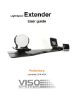
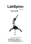
LightSpion Extender User guide Last edited: 2015-08-26 Dimensions 175 cm 43 cm 108 cm 22 cm 28 cm © 2007 Viso Systems ApS, Denmark All rights reserved. No part of this manual may be reproduced, in any form or by any means, without permission in writing from Viso Systems ApS, Denmark. Information subject to change without notice. Viso Systems ApS and all affiliated companies disclaim liability for any injury, damage, direct or indirect loss, consequential or economic loss or any other loss occasioned by the use of, inability to use or reliance on the information contained in this manual. Contents About the LightSpion Extender ....................................... 5 Package contents ........................................................... 5 About this document....................................................... 6 Installation ......................................................................... 7 Software installation ....................................................... 7 Setting up the Extender .................................................. 8 LightSpion alignment ...................................................... 9 Connecting the Extender .............................................. 10 Lamp alignment ............................................................ 11 Lamp connection .......................................................... 13 Making measurements ..................................................... 14 Stray Light Corrections ................................................. 14 Specifications................................................................... 15 3 LightSpion user guide Safety Information Warning! This product is not for household use. Read this manual before installing and operating the controller, follow the safety warnings listed below, and study all the cautions in the manual. Preventing electric shocks Make sure grounded. the power supply is always Use a source of AC power that complies with the local building and electrical codes, that has both overload and ground-fault protection. If the controller or the power supply are in any way damaged, defective, wet, or show signs of overheating, disconnect the power supply from the AC power and contact Viso Service for assistance. Do not install or use the device outdoors. Do not spray with or immerse in water or any other liquid. Do not remove any covers or attempt to repair the controller or the power supply. Refer any service to Viso. Disposing of this product Viso products are supplied in compliance with Directive 2002/96/EC of the European Parliament and of the Council of the European Union on WEEE (Waste Electrical and Electronic Equipment), as amended by Directive 2003/108/EC, where applicable. Help preserve the environment! Ensure that this product is recycled at the end of its lifetime. Your supplier can give details of local arrangements for the disposal of Viso products. 4 LightSpion user guide Introduction About the LightSpion Extender The LightSpion Extender expands the ability of LightSpion to measure the light sources with a diameter of up to 220mm. The device is easily connected to the previously installed LightSpion and gets detected by the Light Inspector software automatically. Package contents The LightSpion package contains the following items: Goniometer base Centre plate LightSpion base plate 5 LightSpion user guide About this document These guidelines describe the installation process of the LightSpion Extender and the alignment of light sources to be measured. 6 LightSpion user guide Installation Software installation Light Inspector software Before the usage of the LightSpion Extender, the “Viso Light Inspector” software version 3.69 or higher must be installed. LightSpion firmware During the installation of the “Viso Light Inspector” software the firmware of the LightSpion is also being checked. It is automatically updated to the latest version in order to enable the most efficient communication with the LightSpion Extender. Use the following link to download the latest version: http://www.lightdataserver.com/software/Viso%20Systems/Ligh tInspector.htm You can always check the installed version at Help->About. The firmware version can also be checked at Help>Firmware information. 7 LightSpion user guide Setting up the Extender The LightSpion Extender comes in 3 parts: Goniometer base Centre plate LightSpion base plate The Extender can be set up in 2 ways. Long configuration The full goniometer-sensor length of 181cm allows the measurements of light sources up to 220mm in diameter. Short configuration The reduced goniometer-sensor length of 114 cm allows the measurements of light sources up to 135mm in diameter. This configuration can be useful when measuring smaller light sources and/or of low power, where a shorter distance will increase the sensitivity of the sensor. 8 LightSpion user guide LightSpion alignment The Extender base plate comes with alignment points and a visual outline for the LightSpion ensuring that the LightSpion is fixed at the right location for accurate measurements. Visual outline Alignment points The alignment points clicks into bottom of the LightSpion as shown below. 9 LightSpion user guide Connecting the Extender The extender’s connection is done via unplugging the built-in goniometer and connecting the RJ45 of the Extender goniometer. The power going to the built-in goniometer lamp holder must also be unplugged and connected to the Extender instead. The Light Inspector software will automatically detect the Extender. Various configurations can be seen in the photometric window. Long configuration Short configuration In case the system does not detect the Extender due to an outdated hardware it is possible to select it manually in Setup->Options. 10 LightSpion user guide Lamp alignment The vertical alignment of the lamp is done automatically by the centred twin clamp holder. Centre The clamps can also be inverted to fix smaller lamps. The location of the holder can also be move to facilitate different lamp types. Position 1 Position 2 The horizontal position of the lamp should be placed in such a way so that the illuminating part is at the centre of rotation, as shown below. 11 LightSpion user guide Centre of rotation Failing to align the lamp to the centre of rotation can affect the accuracy of the peak intensity value and the beam angle. The flux value is not affected by the incorrect horizontal placement. 12 LightSpion user guide Lamp connection The measured lamp is connected using a all-purpose power connector placed on the side of the goniometer base, as shown below. 13 LightSpion user guide Making measurements The LightSpion Extender measurements are done in the exact same way as in the case of LightSpion. Please refer to the LightSpion user manual for further details. Stray Light Corrections Sometimes when measuring particular lamps you can also observe glares. They are reflected from the black surface of the extender plate, enhancing the amount of the light detected by the sensor. Such an example is shown Stray light in the picture to the right: To eliminate the unnecessary illumination we have designed a special stray light blockage. Simply slide it down according to the way it is shown in the pictures below. 14 LightSpion user guide Specifications Physical dimensions Shipping dimensions (L x W x H) ............ 175 (108) x 43 x 28 cm Shipping weight ..................................................................... 3 Kg Dimensions (L x W x H) ........................... 175 (108) x 43 x 28 cm Weight ................................................................................2.5 Kg Sensor distance .................................................. 115 and 182 cm Light sources diameter range ..................................... 0 - 220 mm Light source maximum weight ............................................... 4 Kg Ordering information LightSpion Extender ........................................ P/N EXLIGSP001 15 LightSpion user guide