1
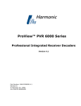
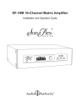
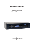
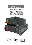
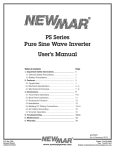
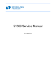
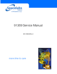
Audio Input Transmitters
For Use with SonaFlex™ Matrix Amplifiers
Installation and Operation Guide
Introduction
FlexPort™ Audio Input Transmitters serve as remote input modules for SonaFlex™ SF-16M Matrix Amplifiers. FlexPort
transmitters are available in several different styles, including balanced line/mic, XLR, digital SPDIF and analog RCA
audio signals. Audio signals are transmitted to an SF-16M via Cat 5e/6/7 cable up to 500 feet and made available to
specified amplified outputs, and can be shared with up to three additional SF-16M amplifiers. Each transmitter has a
convenient override button.
•
•
•
•
Four compatible FlexPort audio transmitters: Stereo RCA, Digital Audio, XLR / TRS, and Balanced Audio (see page 3)
Up to four FlexPort transmitters may be used with one SF-16M (See page 4)
Convenient Override switch provides a simple user interface at the transmitter location
Provides compatability for a mixture of consumer and pro audio sources such as computers, MP3 players, CD and DVD
players, audio streaming devices, performance microphones or paging microphones, and audio mixers
• Differential balanced line technology eliminates interference, enabling FlexPort transmitters to be located up to 500 feet
away from the SF-16M without signal degradation
• Simple connection via one Cat 5/6/7 cable; daisy chain two FlexPort transmitters on each SF-16M input
Double the FlexPort Inputs
Normally, one stereo FlexPort transmitter is connected to each of the two SF-16M FlexPort inputs; however, if mono
signals are used, two FlexPort transmitters may be daisy-chained on each of the FlexPort bus inputs, doubling the
number of possible FlexPort transmitters in one system. There are several ways to configure daisy chained modules.
See page 4.
About the SonaFlex SF-16M
The SonaFlex SF-16M is a unique blend of multi-channel amplification, flexible input options, audio matrix switching,
signal processing and open control capability. Designed and assembled in the U.S. with sound and video integrators in
mind, the SF-16M offers a new approach to commercial and residential distributed audio applications - one multi-purpose
matrix amplifier that can be used in a variety of installations.
Carton Contents
•
•
•
•
FlexPort Audio Input Transmitter (FPM-X, FPM-B, FPM-U, FPM-D)
Screws for both surface mounting and Decora ring mounting
Decora® style face plates in white, ivory, almond, and black
User manual
Other Materials You May Need
• Cat 5/6/7 cable
• Modular RJ-45 connectors
• Audio players, microphones, audio mixers
• Patch cables (optical, RCA, 3.5mm etc.)
Basic Setup Tasks
1. Read this manual to understand FlexPort functions and behavior.
2.Plan your SF-16M system layout and use the PC utility to assign override behavior, and override priority.
3.Install the SF-16M system, including Cat 5e/6/7 wiring for FlexPort transmitters.
4.Assign FlexPort mono/stereo channels, set other dipswitches as needed.
5.Connect Cat 5 bus to FlexPort transmitters, and connect audio sources.
6.Set SF-16M volume levels (adjust gain if necessary).
7.Cycle power on FlexPort transmitters after any change of settings.
NOTE: If the SF-16M will not be used to control volume, set all SF-16M outputs to -0dB (full volume) and adjust volume
in preamplifier.
2
FlexPort Audio Input Modules Installation and Operation Guide
7/29/11
A Release
11/15/11 B
DRA
Remove IR
DAF
BALANCED
AUDIO INPUT
FlexPort Transmitter Models
+
FlexPort audio transmitters can be used to provide up to four additional audio inputs (2 channels per FlexPort input) to
each SF-16M. FlexPort modules connect via Cat 5 cable to the SF-16M and accept a wide variety of pro and consumer
GND
audio sources. All FlexPort modules can be located up to 500 feet from the SF-16M and include mounting points
OVRfor
either surface or in-wall mounting in an “open ended” single gang bracket such as Arlington model LV1 or Carlon model
SC100RR. Remove unused mounting tabs with pliers before installation.
MODEL
FPM-B
1. FPM-B Balanced line/mic input with phantom power
OVERRIDE
BALANCED
AUDIO INPUT
• Accepts any 3-wire balanced or 2-wire unbalanced, line or mic level audio input
+
• “Override” contact closure input for push-to-talk paging mics such as Bogen model MBS1000A
• Override button (defeatable) with backlighting to indicate audioBALANCED
override status
GND
AUDIO INPUT
OVR
• 15V phantom power (defeatable) for condenser microphones
AUDIO INPUT
+
• Input gain potentiometer
L
• Input can be assigned as Dual Mono (2 mono channels), Mono 1GND
or Mono 2 on the FlexPort
OVR
audio bus
• Optional “Mix” setting allows two FlexPort modules to be mixed together on a single FlexPort
audio bus (each input must be assigned to a different mono channel)
2. FPM-X XLR/ 1/4” TRS input with phantom power
MODEL
FPM-B
R
MODEL
FPM-B
DATE
OVERRIDE
LTR REVISION RECORD
AUTH
11/15/11 P1 Prototype
DR
CK
DAF
MODEL
OVERRIDE
FPM-U
AUDIO MIC INPUT
OVERRIDE
• Accepts any 3-wire balanced or 2-wire unbalanced, line or mic level audio input via a combo
XLR / 1/4” TRS input
• Override button (defeatable) with backlighting to indicate audio override status
• 15V phantom power (defeatable) for condenser microphones
• Input gain potentiometer
716-307
• Input can be assigned as Dual Mono (2 mono channels), Mono 1 or Mono 2 on the FlexPort
audio bus
• Optional “Mix” setting allows two FlexPort modules to be mixed together on a single FlexPort
audio bus (each input must be assigned to a different mono channel)
3. FPM-D Digital Coax/Optical Input
Model FPM-B Artwork
MODEL
OVERRIDE
16AN4200
FPM-X
AUDIO MIC INPUT
7/29/11
A Release
11/15/11 B
DRA
Remove IR
DAF
DIGITAL INPUT
AUDIO MIC INPUT
• Accepts any digital SPDIF coax or optical audio input (Stereo PCM only)
COAX
• Override button (defeatable) with backlighting to indicate audio override status
• Input can be assigned as Stereo (default), Mono 1 or Mono 2 on the FlexPort audio bus
OPTICAL
MODEL
FPM-X
L
OVERRIDE
R
AUDIO OUTPUT
• Optional “Mix” setting allows two FlexPort modules to be mixed together on a single FlexPort
audio bus (each input must be assigned to a different mono channel)
• Analog audio output (pass-thru) for applications where a converted analog output is desired
MODEL
FPM-X
1/2
MODEL
FPM-D
OVERRIDE
OVERRIDE
4. FPM-U Analog Audio Input
• Accepts any analog RCA audio input
Ink color: Pantone Cool Gray 8C
BALANCED
• Override button (defeatable) with backlighting to indicate audio
override
status
AUDIO
INPUT
• Input can be assigned as Stereo (default), Mono 1 or Mono 2 on the
+ FlexPort audio bus
AUDIO INPUT
Part Number
• Optional “Mix” setting allows two FlexPort modules to be mixed together on a single FlexPort
GND
audio bus (each input must be assigned to a different mono channel)
Title
L 716-308 R
OVR
Full
Drawing No.
11/15/11
Checked
16AN4300
LTR REVISION RECORD
Sheet
OVERRIDE
MODEL
FPM-U
Rev.
P1
1/2
AUTH
11/15/11 P1 Prototype
MODEL
FPM-B
DRA
Drawn By
Model FPM-X Artwork
Date
DATE
Scale
DR
DAF
OVERRIDE
FlexPort Audio Input Modules Installation and Operation Guide
3
CK
Understanding the FlexPort Audio Bus
Each SF-16M FlexPort input supports:
• Two channels of audio - input can be either stereo or two mono channels (allows two FlexPort transmitters per bus)
• RS-485 data pathway - provides 2-way communication between the SF-16M and all connected FlexPort modules
• 18V power - provides power for up to two FlexPort modules on a single bus
FlexPort Override
761-391
761-392
In addition to the 10 overrides available in the SF-16M, there is an override command for each channel on each FlexPort
bus input (see table). Each FlexPort override button sends a discrete override command to the SF-16M that can be
programmed to connect the associated override channel to any output(s).
FlexPort Bus 1
Ch FlexPort Bus 2
Ch
When used in stereo mode, the Left channel override command connects
both left and right to the assigned output(s). FlexPort input channels can
Left = Override 1
17
Left = Override 3
19
be selected independent of an override command. FlexPort channels are
Right = Override 2 18
Right = Override 4 20
numbered 17, 18, 19 and 20 for SF-16M setup.
BUS IN
™
™
BUS OUT
UT
BUS IN
FPM-B and FPM-X: These are natively mono input
modules - If one mono source input is desired on both
FlexPort bus audio channels, the dipswitch setting
should be set to “Dual M” for dual mono.
FPM-D and FPM-U: These are natively stereo
input modules - Dipswitch setting should be
“Stereo”.
BUS OUT
IN
OUT
CH. ASSIGN
STEREO
MONO 1
MONO 2
SF-16M
FPM-D
FPM-B
CH. ASSIGN
DUAL M
MONO 1
MONO 2
MIN
GAIN
MAX
SWITCH
LINE
OFF
OFF
TOGL.
OFF
ON
Figure 1. Basic FlexPort connection for each bus input. One stereo (or dual mono) source per bus input.
Daisy Chain
ON
ON
MOMENTARY
FlexPort
TERM.
ON
OFF
OFF
TOGL.
Modules
OFF
For Two Mono Inputs Per Bus
All FlexPort audio modules feature a FlexPort Bus In and Out, so any two modules may be daisy chained together for a
two source (mono) setup. In daisy chain configurations, it is required to assign one module as “Mono 1” and the other
module as “Mono 2” using the channel assign switches located on the back of the FlexPort transmitters. Stereo FlexPort
transmitters can assign the left or right channel to be active on the bus. When using a daisy chain configuration for stereo
sources, combine the stereo channels into mono before connecting them to a FlexPort transmitter.
BUS IN
IN
761-392
761-391
761-392
N
BUS IN
IN
OUT
FPM-U
™
™
IN
FPM-B
CH. ASSIGN
STEREO
MONO 1
MONO 2
IN
CH. ASSIGN
OUT
FPM-D
IN
DUAL M
MONO 1
MONO 2
IN
GAIN
MAX
FPM-U
FlexPort Audio Input Modules Installation and Operation Guide
STEREO
MONO 1
MONO 2
SWITCH
MIC
LINE
Figure 2. Daisy chain
for four mono FlexPort
ON transmitters
OFF in a system.
ON connection
OFF
ON
OFF
ON
OFF
Assign each FlexPort
transmitter
to a different mono MOMENTARY
channel on each
TOGL.bus run. Both
MOMENTARY
TOGL.
TERM. ON
only one of the channels
will beOFF
transmitted on the FlexPort
bus. OFF
TERM. ON
PHANT. OFF ON
4
BUS OUT
CH. ASSIGN
MIN
SWITCH
LINE
OFF
OFF
Y TOGL.
OFF
ON
™
™
BUS OUT
BUS OUT
OUT
H
BUS IN
SF-16M
SWITCH
channels can
ON
OFF
ON
OFF
beMOMENTARY
connected, TOGL.
but
TERM. ON
OFF
SWITCH
MIC
ON
ON
MOMENTARY
TERM. ON
PHANT. OFF
LIN
OF
OF
TO
OF
ON
FPM Rear Panel Connections and Settings
FPM-B and FPM-X
FPM-B and FPM-X
A FlexPort Bus In - Connects via Cat 5 to the FlexPort “Bus Out” of
another FPM in daisy chain scenarios
for audio settings when daisy chaining)
761-392
761-391
B FlexPort Bus Out - Connects via Cat 5 to a SF-16M “FlexPort In” or in
daisy chain configurations to the “Bus In” of an additional FPM (See D
A
BUS IN
B
BUS OUT
C Input Gain - Increase or decrease input signal level prior to being sent to
the SF‑16M
D Assign Channel - The input source can be assigned as: Dual Mono
(input is assigned to both FlexPort channels), Mono 1 (FlexPort bus
channel 1) or Mono 2 (channel 2)
CH. ASSIGN
MIN
DUAL M
D MONO
1
E DIP Switch Settings:
™
MONO 2
MAX
Input Mic/Line - Sets input gain as mic or line level
Mix On/Off - Mix two channels into a mono channel. Allows two daisy
chained FlexPort modules to mix together upon override. Also combines
left and right on one stereo transmitter.
Override On/Off - Enables or Disables override button on the front panel
Momentary/Toggle - Sets the override button to respond as a
momentary or toggle switch
Bus Termination On/Off - Turn on if the FPM is the last module in a
daisy chain configuration
Phantom Power On/Off - Turn on for phantom powered microphones
C
CH. ASSIGN
GAIN
STEREO
MONO 1
MONO 2
SWITCH
MIC
ON
ON
MOMENTARY
TERM. ON
PHANT. OFF
E
LINE
OFF
OFF
TOGL.
OFF
ON
ON
ON
MOM
TERM
Figure 4
FPM-D and FPM-U
FPM-D and FPM-U
G FlexPort Bus In - Connects via Cat 5 from the FlexPort “Bus Out” of
another FPM in daisy chain scenarios
761-392
761-391
F FlexPort Bus Out - Connects via Cat 5 to a SF-16M “FlexPort In” or in
daisy chain configurations to the “Bus In” of an additional FPM (See I
BUS IN
for audio settings when daisy chaining)
G
BUS IN
F
BUS OUT
H Assign Channel Switch - The input source can be assigned as: Stereo
(default), Mono 1 (FlexPort bus channel 1) or Mono 2 (channel 2)
I DIP Switch Settings:
™
BUS OUT
Mix On/Off - Mix two channels into a mono channel.
Allows two daisy
CH. ASSIGN MIN
chained FlexPort modules to mix together uponDUAL
override.
Also combines
M
GAIN
MONO 1
left and right on one stereo transmitter.
MONO 2
CH. ASSIGN
STEREO
H MONO 1
MONO 2
MAX
Override On/Off - Enables or Disables override button on theSWITCH
front panel
MIC
Momentary/Toggle - Sets the override button to respond ON
as a
ON
momentary or toggle switch
MOMENTARY
TERM. ON
LINE
OFF
OFF
TOGL.
OFF
ON
™
SWITCH
I
PHANT. OFF
Bus Termination On/Off - Turn on if the FPM is the last module
in a
daisy chain configuration
ON
ON
MOMENTARY
TERM. ON
OFF
OFF
TOGL.
OFF
Figure 5
FlexPort Audio Input Modules Installation and Operation Guide
5
BALANCED
AUDIO INPUT
AUDIO INPUT
+
L
R
GND
OVR
FlexPort Override Button
DATE
LTR REVISION RECORD
AUTH
DATE
11/15/11
P1 Prototype
7/29/11 outputs
A Releaseto a
DRA
The override button on a FlexPort front panel is used to switch designated SF-16M
FlexPort
input. When
11/15/11 B Remove IR
DAF
the override button is pressed, it triggers a programmable override event (see PC
Utility). A typical application would
MODEL
MODEL
be an audio mixer, connected to an FPM-X in a conference
room. Normally
background music is playing
from aOVERRIDE
source
OVERRIDE
FPM-B
FPM-U
connected to the SF-16M. When the override button is pressed, designated outputs switch from background music to
the audio mixer for the duration of the override. When the override button is pressed again, (in Toggle mode) all affected
outputs switch back to the background music source. When two FlexPort transmitters share a single bus, they must be
set to operate independently, or to mix their signals, as shown in the example below.
DR
CK
LTR REVISION
7/29/11 DAF
A Release
11/15/11 B
Remove
Override behavior is based on two key settings: 1.FlexPort dip switch settings (see page 5).
2.SF-16M audio override settings, programmed using the716-307
SF-16M PC
configuration utility (see the PC configuration utility manual for more
Model FPM-B Artwork
information on audio override settings).
1/2
16AN4200
Example: Mix Option Enabled
In some cases it may be desired to mix together
inputs from two FlexPort transmitters when both
BALANCED
AUDIO INPUT
audio overrides are active. An example would
be a
conference room where both a microphone and an+
audio presentation should be heard simultaneously.
DIGITAL INPUT
AUDIO MIC INPUT
MIC
INPUT
AUDIO INPUT
L
DVD PLAYER
OPTICAL
RIGHT RCA ONLY
COAX
R
GND
OVR
• Set one FlexPort as “Mono 1”, and set the other
as
“Mono 2”.
• Turn on the “Mix” dipswitch on one of the
transmitters, so that the SF-16M will mix the
MODEL
MODEL
channels together for all outputs in the system.
OVERRIDE
OVERRIDE FPM-X
FPM-B
• In the PC utility, designate outputs for overrides
(e.g. 17 and 18).
FPM-X FRONT VIEW
FPM-X BACK VIEW
(USE “Y” ADAPTER)
DATE
LTR REVISION RECORD
11/15/11 P1 Prototype
MODEL
FPM-U
DATE
2
IN
LINK
SPEED
CONTACT CLOSURE
761-392
761-391
FlexPort 1
FlexPort 2
IN
IN
OUT
Part Number
OUT
716-308
Scale
Full
Drawing No.
™
™
CH. ASSIGN
MIN
STEREO
MONO 1
MONO 2
GAIN
MAX
LINE
OFF
OFF
TOGL.
OFF
ON
STEREO
1
STEREO ZONE 2
ForZONE
additional
application examples, see
COAX
OPTICAL
audioauthority.com/appex
MIX ON
SWITCH
MIC
ON
ON
MOMENTARY
TERM. ON
PHANT. OFF
SWITCH
MODEL
FPM-X
4
ON
ON
MOMENTARY
TERM. ON
OVERRIDE
OFF
OFF
TOGL.
OFF
1/2
Rev. Date
P111/15
5
6
STEREO ZON
MODEL
FPM-D
OVERRIDE
TERMINATION OFF
Part Number
716-308
Scale
Full
Drawn By
DRA
Date
11/15/11
Drawing No.
16AN4300
Part Num
7
Checked
Note: in this case, the overrides for both transmitters (17 and 18) are programmed to perform
the same action, so the
Title
Model FPM-X Artwork
override may be triggered or cancelled from either transmitter.
FlexPort Audio Input Modules Installation and Operation Guide
Sheet
L
R
AUDIO OUTPUT
Figure 6. In this example, a microphone is connected to an FPM-X transmitter, and DVD player audio outputs are
connected to an FPM-U transmitter. Both FlexPort transmitters are on the same Cat 5 bus run.
BothPantone
transmitters
Ink color:
Cool Grayhave
8C the
Override switch on and one transmitter has the Mix switch on. When the override switch is active on the Mix transmitter,
the audio from both transmitters is mixed by the SF-16M for output to all speakers in the conference room.
6
7
Title
DIGITAL INPUT
AUDIO MIC INPUT
DUAL M
MONO 1
MONO 2
1
2
(OVERRIDES
17 AND 318)
BUS OUT
AU
DRAPart Num
Checked
Model FPM-B ArtworkModel FPM-X Artwork
Date
CH. ASSIGN
Drawn By
Title
SF-16M
16AN4300
1/2
16AN420011/15/11
FLEXPORT INPUT 2
BUS OUT
D
Ink color: Pantone Cool Gray 8C
5V - 24V AC / DC
716-307
BUS IN
ETHERNET
UNIT ID
OUT
LTR REVISIO
11/15/11 P1 Prototyp
MODELSYSTEM
OVERRIDE
FPM-D TRIGGER
AUDIO
OVERRIDE
OVERRIDE
1
CK
FPM-U FRONT VIEW
FPM-U BACK VIEW
BUS IN
L
R
AUTH
DR
AUDIO
OUTPUT
DAF
Sheet
1/2
Rev.
P1
Title
Date
11/15
OVERRIDE
1
TRIGGER
2
IN
UNIT ID
OUT
ETHERNET
LINK
SPEED
Connecting to the SF-16M
CONTACT CLOSURE
FlexPort Transmitters connect directly to SF-16M inputs, or via
other FlexPort Transmitter bus inputs (daisy chain). One or both
FlexPort bus inputs may be shared with up to three SF-16M
amplifiers using the FlexPort bus output jacks. Alternatively, each
SF-16M amplifier in a system can have its own independent
FlexPort transmitters that are only available to the local SF-16M
outputs.
FlexPort 1
FlexPort 2
IN
IN
OUT
1
SYSTEM
TRIGGER
2
IN
UNIT ID
OUT
ETHERNET
Audio Authority® Corp. • 2048 Mercer Rd. Lexington, KY 40511 USA
800-322-8346 • 859-233-4599 • www.audioauthority.com
A
BUS
5V - 24V AC / DC
FlexPort 2
IN
OUT
LINE INPUTS
1
FlexPort 1
IN
AUDIO LOOP OUTPUT
2
3
4
5
6
B
3
C
5
7
E
9
Model SF-16M 16-Channel Matrix Amplifier
F
11
G
13
H
MAIN IR
IN
15
PDF User Manual
5
8
4002715
ETL LISTED CONFORMS
TO UL STD 60065
CERTIFIED TO CAN/CSA
STD C22.2 NO. 60065
RS-232 IN
STEREO ZONEVOLTAGE
1 SELECTOR
Set voltage selector
STEREO ZONE 2
and install correct
fuses according to
local power supply.
R
4
6
SPEAKER OUTPUTS (CLASS 2 WIRING)
7
D
L
2
1
4
701-13303B
USB
DB25 AUDIO INPUT
OUT
3
2
LINK
SPEED
CONTACT CLOSURE
OUT
SF-16M FlexPorts
1
AUDIO
OVERRIDE
5V - 24V AC / DC
9
10
8
10
12
11
14
12
MAIN IR
OUT
16
13
14
RS-232 OUT
15
STEREO Z
Régler le sélecteur
de tension et
installer les fusibles
corrects selon
l’alimentation locale.
16
100-120V~ 50-60 Hz
1125W
STEREO ZONE 1
STEREO ZONE 2
STEREO ZONE 3
STEREO ZONE 4
STEREO ZONE 5
STEREO ZONE 6
STEREO ZONE 7
Replace Fuses Only
with T 10A, 250V
Remplacer Uniquement
avec Fusible T 10A, 250V
STEREO ZONE 8
701-13303
Category Cable Fabrication and FlexPort
RJ-45 Pinout
It is recommended that all FlexPort bus wiring be
configured using the EIA-568B standard pinout.
Audio Authority cannot garantee correct operation
using any other wiring configuration. Pre-made
network cables or site-fabricated cables may be used
(EIA-562A or B standard). E-Z Cat 5 cable plugs are
recommended. Always test Category cables with a
network cable tester, not simply a continuity tester –
cables must be paired correctly for proper functionality.
SF-16M 120V Rear Panel Artwork
16BN4020
FlexPort Pinout:
(EIA-568B)
Pin 1: RS-485A
Pin 2: RS-485B
Pin 3: Audio Left +
Pin 4: Audio Right +
Pin 5: Audio Right –
Pin 6: Audio Left –
Pin 7: 18V
Pin 8: Ground
1/2
Pair 3
Pair 2
Pair 1
Pair 4
Modular Jack (RJ-45)
1 2 3 4 5 6 7 8
W-O O W-GR BL W-BL GR W-BR BR
T568B Pair Assignments
Troubleshooting Guide
Low volume
Check the mic/line dipswitch (FPM-X or FPM-B) when using a mixer or other line level
source. The factory default setting is line level. If volume is still low, adjust the GAIN pot.
Poor sound quality
Make sure two transmitters daisy chained on one bus are set to Mono 1 and Mono 2.
Override button does not
function
Make sure Termination is on. For daisy chain, turn off Termination for the transmitter farthest
from the SF-16M.
Override must be set up using the PC utility; designate input, output, and priority.
No mic power
For microphones that accept phantom power, turn PWR Phant. ON.
Only one channel plays
from stereo source
Check the CH. ASSIGN switch. If using daisy chain configuration with stereo sources, use a
stereo to mono adapter to hear both channels in mono.
Override button does not
stay on when pushed
Turn off MOMENTARY/TOGL. dipswitch to activate the toggle function.
FlexPort Audio Input Modules Installation and Operation Guide
7
FlexPort Transmitter Specifications
S/N Ratio:
96dB
Channel Separation:
70dB(channel to channel @1kHz)
Input Sensitivity:
0.5Vrms
Input Z Impedance:
FPM-U: 20k Ohms, FPM-D: 75 Ohms, FPM-X and FPM-B: 2k Ohms
Accepted Bit Rates (FPM-D)
44.1, 48, or 96KHz
Dimensions (H x W x D):
4 x 1.65 x 3.65 including mounting tabs; 2.8 x 1.65 x 3.65 without tabs (inches)
Net Weight:
9.5 oz. (270g)
Shipping Weight:
12 oz. (340g)
Approvals
FCC
Warranty:
Two years, parts and labor
Limited Warranty
If this product fails due to defects in materials or workmanship within two years from the date of the original sale to the
end-user, Audio Authority guarantees that we will repair or replace the defective product at no cost. Freight charges
for the replacement unit will be paid by Audio Authority (Ground service only). A copy of the invoice from an Authorized
Re-seller showing the item number, serial number, and date of purchase (proof-of-purchase) must be submitted with
the defective unit to constitute a valid in-warranty claim.
Units that fail after the warranty period has expired may be returned to the factory for repair at a nominal charge, if not
damaged beyond the point of repair. All freight charges for out-of-warranty returns for repair are the responsibility of
the customer. Units returned for repair must have a Customer Return Authorization Number assigned by the factory.
This is a limited warranty and is not applicable for products which, in our opinion, have been damaged, altered,
abused, misused, or improperly installed. Audio Authority makes no other warranties either expressed or implied,
including limitation warranties as to merchantability or fitness for a particular purpose. Additionally, there are no allowances or credits available for service work or installation performed in the field by the end user.
This product has been tested by an accredited laboratory and meets the
provisions of FCC 47 CFR Part 15.
(b) Operation of an intentional, unintentional, or incidental radiator is
subject to the conditions that no harmful interference is caused and that
interference must be accepted that may be caused by the operation of an
authorized radio station, by another intentional or unintentional radiator,
by industrial, scientific and medical (ISM) equipment, or by an incidental
radiator.
(c) The operator of a radio frequency device shall be required to cease
operating the device upon notification by a Commission representative that
the device is causing harmful interference. Operation shall not resume until
the condition causing the harmful interference has been corrected.
2048 Mercer Road, Lexington, Kentucky 40511-1071 USA
Phone: 859-233-4599 • Fax: 859-233-4510
Customer Toll-Free USA & Canada: 800-322-8346
www.audioauthority.com • [email protected]
v 1.0
752-634
10/12