1
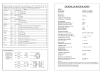
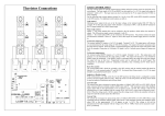
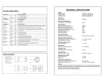
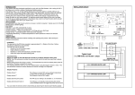
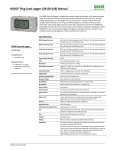
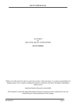
X20092 DMFC36 User manual KEY FEATURES Standard DIN Rail Mounting Selectable modes of control : Phase Angle or Burst Fire (SingleCycle/Dual-Cycle & adjustable STD Burst Firing) On Board Indication of Power, Burst-Rates & Fault conditions Inhibit input Wide Range of Control Options (0-5V, 0-10V, 1-5V, 2-10V, 0-20mA, 4-20mA, Manual Potentiometer) On board protection fuse Isolated Pulse Transformer outputs Soft Start Auto Phase-Rotation detection Issue: 2 Date: 31/10/14 Page: 1 of 10 INTRODUCTION The DMFC36 driver module has been designed to offer both phase angle & burst fire control of thyristor controllers driving Resistive loads. The Single-Cycle & Dual-Cycle options offer the fastest burst rates possible, providing very accurate control and mininising Harmonic distortion & Flicker within the system. In addition, the standard variable burst rate, adjustable from 1 to 30 seconds, is also available. The DMFC36 software also includes auto phase rotation. Designed to be used in conjunction with a thyristor assembly or supplied on one of our complete thyristor controllers, the DMFC36 offers a highly versatile and cost effective solution in a wide variety of applications. The DMFC36 is commonly used in three phase applications with both 3-Wire and 4-Wire load configurations (including Closed-Delta, Floating-Star & Star to Neutral), where all three limbs are controlled (fully controlled circuit). The DMFC36, operating in Burst-Fire mode, is also commonly used in three phase, 3-Wire load configurations (including Closed-Delta & Floating-Star), where only two limbs are controlled (2/3rds controlled circuit). For ease of mounting & for protection purposes, the controller comes in a DIN Rail Enclosure. TECHNICAL SPECIFICATIONS Std Supply Voltage 420/460 VAC selectable via LINK J1 (other supply voltages available) Supply Frequency 50/60 Hz Auxiliary Supply Voltage 24V AC/DC (500mA minimum) Power Consumption 7 VA Internal Fusing 1 Amp 32mm fuse Protection Rating IP20 Operating Temp Range 0-65°C Input Signal Options 0-5VDC, 0-10VDC, 1-5VDC, 2-10VDC, 0-20mA, 4-20mA, Manual Potentiometer Output Specification Pulse transformer picket-fence 25kHz pulse output. Initial pulse 500mA & Sustaining pulses of 250mA Output Isolation 3.5 KV Soft Start (Ramp Speed) 0-30 seconds (adjustable) STD Burst-Fire Cycle Time Minimum 1s to Maximum 30s variable. Selectable via switch SW1 Rapid Burst-Fire Cycle Time Single-Cycle/Dual-Cycle variable time base, selectable via switch SW1 Green LED indicator Power ON, indicating when 5 VDC is present Red LED indicator LED ON continuously indicates phase loss between K2 phase 1 & K2 phase 2 LED slow flashing indicates no current control signal (4-20mA) LED fast flashing indicates incompatible 2-Leg control & 4-Wire load selected Yellow LED indicator Burst-Rate indicator, mimics the output burst-rate Safety Standards Complies with European Low Voltage Directive & major international standards Page 2 of 10 TERMINALS & CONNECTIONS Terminal Function Notes 9-way terminal block reading from Left-Right 1 5V DC output (50mA max.) This supply used to feed 5VDC to the clockwise end of the manual control potentiometer or auxiliary circuit. 2 +VE voltage control signal input +ve control signal input from Temperature Controller or connect to wiper of a manual control potentiometer 3 Ground / 0V -VE voltage control signal input -VE control signal input from Temperature Controller or connect to the counter clockwise end of the manual control potentiometer. 4 +VE Current signal input +VE Current signal input, 0-20mA or 4-20mA 5 Ground / 0V -VE Current signal input, 0-20mA or 4-20mA 6 INHIBIT CLOSE Contacts to DISABLE (shut down) controller 7 INHIBIT OPEN Contacts to ENABLE the controller 8 (Common 0V Line) External -VE 24VDC supply only required if supply to L1 and L2 are not being used 9 +24V AC or DC input External +VE 24VDC supply only required if supply to L1 and L2 are not being used Additional Connections HI/LO High / Low Jumper Link Select High or Low supply voltage range L1 & L2 AC Supply input use any 2 phases or phase and Neutral. AC supply only required if 24V DC supply to terminals 8 and 9 are not being used G1 & K1 Output connections to Thyristor’s Timing reference inputs from K2 of Phase 1 and K2 of Phase 2 are taken from here G2 & K2 Page 3 of 10 SWITCH SETTINGS SW1 Settings Notes ON=1 (UP) OFF=0 (DOWN) SW1 6 way DIP switch Brown Switch ON Phase Angle Enabled Brown Switch OFF Phase Angle Disabled Red Switch ON Burst Fire Enabled Red Switch OFF Burst Fire Disabled Orange Switch ON VR1 Clockwise : Dual Cycle VR1 Anti-Clockwise : Single Cycle Orange Switch OFF Variable Burst Rate set by VR1 TIME BASE 1 to 30 seconds Yellow Switch ON Offset ON Yellow Switch OFF Offset OFF Green Switch ON When this switch is ON it sets an offset of 20%, this mode is used for control signals which do not start from 0, such as 1-5V, 2-10V and 420mA. Green Switch OFF In this position there is no offset, this mode is used for control signals starting from 0, such as 0-5V, 0-10V and 0-20mA. Blue Switch ON The controller is set for a 3-Wire configured load (Closed-Delta or Floating-Star), where there is no Neutral connection. Blue Switch OFF The controller is set for 4-Wire configured load (Star to Neutral), where there is a Neutral connection to the Star Point. Note in this position the Green switch must be switched OFF Purple Switch ON The controller is set up to control 2 limbs L1 and L2 of `a three phase load L3 is connected directly to the load, Neutral must not be connected in this configuration Purple Switch OFF The controller is set up to control all 3 limbs of a three phase load the star point maybe floating or connected to Neutral Grey Switch ON The controller is set for 0-10V DC control signals Grey Switch OFF The controller is set for 0-5V DC control signals and manual control uses a 5K Potentiometer Page 4 of 10 WIRING (THYRISTOR CONNECTIONS) Page 5 of 10 APPLICATION CIRCUITS Typical 3-Phase, 3-Wire, 4-Wire & 6-Wire Load configurations (all three phases switched) Typical 3-Phase, 3-Wire Load configurations (only two of three phases switched) Burst-Fire mode only TERMINAL CONNECTIONS 2 Connections are made to the above terminals which will accept wires up to 1.5mm cross section. The use of screened cable is not usually necessary for control signal wiring within a panel. Normal precautions should be taken to keep signal wiring away from power cables, in particular avoid running signal cables parallel to power cables in the same trunking. See ITA datasheet for more information. PHASE REFERENCE The phase references, for the zero voltage detection circuit is taken from both of the K2 connections of PHASE 1 and PHASE 2, this phase reference is provided by the Cathode connections of the thyristor modules so the correct orientation of the thyristor modules is required see the schematic diagram. If the line supply to either of these phases is not present the Red LED will be on continuously and the output drive will be inhibited until the supply to these phases is reinstated. Page 6 of 10 WAVEFORMS (TYPICAL FOR SINGLE-CYCLE & DUAL-CYCLE SWITCHING) The following diagrams show representations of voltage waveforms for Burst-Fire (Single-Cycle & Dual-Cycle switching) operation. The heavily outlined portion of the sinusoidal train indicates when the thyristors are switched on, and the lighter portion indicates when they are off. The waveforms show zero voltage (and thus current) switch on, and zero current switch off. A more comprehensive set of waveforms and Harmonics information is available in a separate appendix document Ref : X10789 EMC Standards Complies with the European EMC Directive for operation in an industrial environment The following standards have been applied in whole or in part in the design of this controller; EN61010-1, EN61000-6-2, EN 50 081 part 2 Page 7 of 10 DIMENSIONS FIXING Unit should be installed on TS35 DIN rail via DIN clip on base of control module WEIGHT DMFC36 module <500g Page 8 of 10 RECOMMENDATION & SAFETY REQUIREMENTS SUPPORTING DATASHEETS FOR PRODUCTS AND APPLICATIONS Other documents, which may be appropriate for your applications, are available on request. CODE IDENTITY DESCRIPTION X10772 3-RFI Filter recommendation: Addressing the EMC directive. X10213 ITA Interaction: Uses for phase angle and for burst fire control. X10255 SRA Safety requirements: Addressing the Low Voltage Directive (LVD) including, Thermal data/cooling, Live parts warning Earth requirements and Fusing recommendations. X10322 APC Application Circuits. X10789 WAV Single or Dual Cycle Waveforms & Harmonics Data. NOTE: It is recommended that installation and maintenance of this equipment should be carried out by suitably qualified personnel, with reference to the current edition of the I.E.E. Wiring Regulations BS7671. The regulations contain important requirements regarding the safety of electrical equipment. Not for general waste Page 9 of 10 ORDER CODES Basic Instrument DMFC36 DMFC36 DMFC36 Supply 420/460VAC 50 Hz and 24V AC/DC 480VAC 50Hz 380/500VAC 24V AC/DC input UAL Order Code A34571 A34572 A34573 PRODUCT APPLICATION The DMFC36 offers Phase Angle, Burst fire or Single-Cycle/Dual-Cycle (Rapid Burst Firing) control where minimum fluctuation in heater element temperature is required. This type of Rapid Burst Fire is useful if a system has a high impedance supply as a result of long power leads or if the system is powered by a generator set. Normally this can result in the supply being subject to mains dips, but this option minimises the ‘Flicker’ effect on the mains supply. Another benefit of using this type of control is that you avoid high ‘Harmonic Distortion’ normally associated with phase angle control, typically down to levels of below 4%. The DMFC36 can be started in phase angle mode and switch to burst mode when the control signal ramps up to the set point. It will stay in the burst mode even if the signal drops below the set point. It will restart in phase angle mode when the unit is switched off or reset. Southport Business Park, Wight Moss Way, Southport, PR8 4HQ Tel: +44 (0)1704 516500 Fax: +44(0)1704 516501 Email:[email protected] Web:www.united-automation.com