1
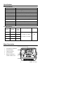
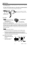
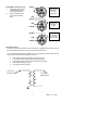
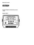
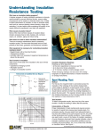
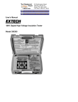
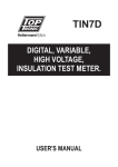
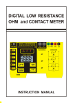
User's Manual
Digital High Voltage Insulation Tester
Model 380375
Warranty
EXTECH INSTRUMENTS CORPORATION warrants this instrument to be free of defects
in parts and workmanship for one year from date of shipment (a six month limited
warranty applies on sensors and cables). If it should become necessary to return the
instrument for service during or beyond the warranty period, contact the Customer
Service Department at (781) 890-7440 ext. 210 for authorization or visit our website at
www.extech.com (click on Contact Extech and go to Service Department to request an
RA number). A Return Authorization (RA) number must be issued before any product is
returned to Extech. The sender is responsible for shipping charges, freight, insurance
and proper packaging to prevent damage in transit. This warranty does not apply to
defects resulting from action of the user such as misuse, improper wiring, operation
outside of specification, improper maintenance or repair, or unauthorized modification.
Extech specifically disclaims any implied warranties or merchantability or fitness for a
specific purpose and will not be liable for any direct, indirect, incidental or consequential
damages. Extech's total liability is limited to repair or replacement of the product. The
warranty set forth above is inclusive and no other warranty, whether written or oral, is
expressed or implied.
Introduction
Congratulations on your purchase of Extech’s High Voltage Insulation Tester. This device
has four voltage test ranges (up to 5kV) and measures insulation resistance to 250GΩ.
This professional meter, with proper care, will provide years of safe reliable service.
Safety
1.
Circuits under test must be de-energized and isolated before connections are made.
2.
Circuit connections must not be touched during a test.
3.
After insulation tests, capacitors must be discharged.
4.
Test leads (including alligator clips) must be in good working order, clean and without
broken or cracked insulation.
5.
When servicing, use only specified replacement parts.
6.
Environmental conditions:
•
Indoor use only; Installation category II
•
Pollution degree 2
•
Altitude up to 2000 meters
•
Relative Humidity 80% max.; Temperature 0 to 40 C
o
International Safety Symbols
Caution, refer to this manual before using this meter
Dangerous Voltages; risk of electric shock
Meter is protected throughout by double or reinforced insulation
2
380375 V1.5 3/04
Specifications
General specifications
Display
2 x 16 character alphanumeric multi-function dot matrix
Range selection
Automatic ranging
Bargraph
Displays voltage ramp, soak, and decay
Automatic discharge
After automatic & manual stop or upon completion of test
Low battery indicator
"Replace battery" displayed when battery voltage is low
Power source
Eight 1.5V AA cells; Battery life 40 hrs (no load at 5kV)
Auto Power off
After 30 minutes
Enersave
TM
mode
Shorter test time to conserve battery life
o
o
Operating conditions
32 to 104 F (0 to 40 C); < 80% RH
Storage conditions
14 to 140 F (-10 to 60 C); < 80% RH
Dimensions
4.7 x 6.7 x 3.7” (120 x 170 x 95mm)
Weight
1.94 lbs (880g)
o
o
Range Specifications
Test
Voltage
Resistance
Ranges
Short
Circuit
Current
Accuracy
Resolution
500V DC
0 to 25 GΩ
1mA
1000V DC
0 to 50 GΩ
1mA
0 to 50GΩ: ± 3% reading
1kΩ
2500V DC
0 to 125 GΩ
1mA
50 to 250GΩ: ± 5% reading
5000V DC
0 to 250 GΩ
1.6 mA
Meter Description
1
\
1.
Test lead jacks compartment
2.
Dot Matrix Display
3.
Voltage test buttons
4.
ON / TEST button
5.
Battery compartment is
located on bottom of unit
2
3
4
5
3
380375 V1.5 3/04
Operation
Note: Ensure that the circuit under test does not include devices or components that can
be damaged by 5000VDC; such devices include power factor correction capacitors, low
voltage mineral insulated cables, electronic light dimmers, ballasts and starters for
fluorescent lamps.
Connecting the Test Leads to the meter
The Black (Earth) and Red (Line) test leads connect to the meter in the lead compartment
located on the back of the meter (the meter jacks are color coded). NOTE: The Green
(Guard) lead is typically not used. Do not connect this test lead to the meter unless
absolutely certain it is going to be used. For more information, continue reading this
Operation section and the Applications section to follow.
Connecting the Test Leads to the device under test
The Black (Earth) lead is connected to the conductive material. The Red (Line) lead is
connected to the insulating material. The Green (Guard) lead is at the same potential as
the negative terminal (0V) and, when required, is used to prevent erroneous readings by
removing parallel leakage paths from the measurement.
Insulation Resistance Measurements
1. Connect the test leads to the meter and the device under test.
2.
Press the ON / TEST button to turn the unit on. The
unit will display the turn-on screens and then stop at
the “Select Test” display.
3.
Select the desired test voltage by pressing the 500V,
1KV, 2.5KV, or 5KV button. The screen will briefly
Connect Leads
display the selected test voltage and then will proceed
Testing for LIVE
to the “Connect Leads Testing for LIVE” display. If the
circuit is “live” the display will indicate “Live Warning… Circuit Live” and the meter will
beep. If this occurs, remove the test leads and press the ON / TEST button.
4.
Press the ON / TEST button to apply the voltage and begin the test. The meter will
beep every 2 seconds which indicated high voltage is on the test leads and the meter
will intermittently buzz while the high voltage is being generated.
5.
On the display, elapsed test time appears on the
upper right, the resistance reading appears on the
upper left, the selected voltage is shown on the lower
right and the bar graph indicates the actual voltage
present on the test leads.
R= 108.2MΩ
0 ██████
6.5s
500V
6.
At the completion of the test the meter will discharge
R= 128.4MΩ
the device under test and the display “HOLD”. Do not
0
HOLD
remove the test leads until the bargraph disappears
(complete discharge) and “HOLD” appears in the display.
7.4s
500V
7.
The meter automatically discharges the system at the end of the test. The test ends
when one of the following occurs.
Select Test
2.5kV, 1kV,
TM
mode.
a.
After approximately 10 seconds in the Enersave
b.
After approximately 100 seconds in the continuous mode.
c.
When the red ON / TEST button is pressed.
4
5kV
500V
380375 V1.5 3/04
TM
The Enersave
Mode
TM
Enersave conserves battery life by reducing the test time from 100 seconds to approx.
TM
TM
10 seconds. Enersave is the default mode of operation. To disable Enersave press
and hold the ON / TEST button for three seconds to begin a test.
Bargraph Voltage Display
The bargraph represents the voltage present on the test leads as it charges, soaks, and
discharges. The bargraph appears on the lower portion of the display during tests.
Automatic Low Resistance Detect
If the display shows the message “LOW MΩ”, the test should be interrupted immediately
by pressing the ON / TEST button. This message indicates that the insulation under test
has broken down and the meter is trying to inject a high potential onto a short circuit.
Elapsed Timer
The test duration is indicated on the display. This is particularly useful in determining
whether an insulating material under test will break down in a given amount of time.
Manual Test STOP
To stop a test in progress, press the ON / TEST button. The test will immediately end and
the system will automatically discharge.
Automatic Test STOP
TM
The test automatically stops after 100 seconds if the meter is not in the Enersave mode.
TM
When in the Enersave mode, the test automatically stops after approx. 10 seconds.
Live Circuit Warning
If the test leads are connected to a live circuit when testing, a warning beeper will sound
and the meter will display “Live Warning…Circuit Live…”. In this case, correct the problem
and retest.
Automatic Discharge
At the end of a test, the meter automatically discharges the high voltage. The automatic
discharge status is reflected on the display. During discharge the beeper will sound and,
when completely discharged, the HOLD icon appears on the display.
Auto OFF
The meter will automatically turn off after approximately 30 minutes of operation.
5
380375 V1.5 3/04
Applications
Measuring Power Tools and Small Appliances
For small appliances, connect the Black (EARTH) lead to conductors and the Red (LINE)
lead to insulating material.
For single or double insulated power tools, one lead should be connected to the device’s
chuck, blade, etc. and the other lead to one of the AC power cord conductors (test both
conductors in turn). Refer to the power tool application diagram below.
AC
Plug
For 2 or 3 prong plugs, connect the
RED lead to one conductor at a time
Connect the BLACK
lead to the chuck
Testing Motors
AC Motors
Connect BLACK lead
Disconnect the motor from the line by:
to the motor leads
a. Disconnecting the wires from the
motor terminals or
Connect RED lead
b. Opening the main switch
to grounded housing
If the main switch is opened, and the
motor also has a motor-starter, then
the starter must be held in the ON position. With the main switch opened, the measured
resistance will include the resistance of the motor wire and all other components between
the motor and the main switch. If a weakness is indicated, the motor and other
components should be checked individually. If the motor is disconnected at the motor
terminals, connect the RED lead to the grounded motor housing and the BLACK lead to
one of the motor leads.
DC Motors
1.
Disconnect the motor from the line.
2.
To test the brush rigging, field coils and armature, connect the RED lead to the
grounded motor housing and the BLACK lead to the brush on the commutator.
3.
If the resistance measurement indicates a weakness, raise the brushes off of the
commutator and separately test the armature, field coils and brush rigging by
connecting one lead to each individually, leaving the other connected to the grounded
motor housing. This also applies to DC Generators.
Testing Single Conductor Cables
1.
Completely disconnect the cable
under test from its source and
destination.
2.
Connect the test leads to the
cable as shown at right.
Core
EARTH
6
Insulation Sheath
GUARD
Covering
LINE
380375 V1.5 3/04
Testing Multi Conductor Cables
1.
Completely disconnect the
cable under test from its
source and destination.
2.
Refer to the diagrams at
right for three possible
tests.
EARTH
Testing one
conductor to
all of the
conductors
LINE
EARTH
Testing one
conductor
to earth
LINE
GUARD
GUARD
Testing one
conductor to
all conductors
minus ground
LINE
EARTH
Transformer Testing
Transformer tests are performed with the transformer completely disconnected from the
line and the load. Note that the case ground should not be removed.
The five tests listed below will completely test a single-phase transformer. Note that at
least 1 minute should be allowed between each test.
1.
2.
3.
4.
5.
High voltage winding to low voltage winding and ground
Low voltage winding to high voltage winding and ground
High voltage winding to low voltage winding (pictured below)
High voltage winding to ground
Low voltage winding to ground
Connect the
BLACK lead here
Connect the
RED lead here
7
380375 V1.5 3/04
Maintenance
Battery Replacement
When ‘REPLACE BATTERY’ appears on the display, replace the eight 1.5V ‘AA’ batteries.
1. Ensure that the meter is powered down and that the test leads are not connected
2.
Close the instrument cover and turn the instrument upside down
3.
Remove the phillips head screw located on the bottom of the meter
4.
Remove the battery compartment cover
5.
Replace the eight batteries ensuring proper polarity
6.
Affix the rear cover and secure the rear screw
Cleaning
Periodically wipe the case with a dry cloth. Do not use solvents or abrasives to clean this
instrument.
Repair and Calibration
Extech offers complete repair and calibration services for all of the products we sell. For
periodic calibration, NIST certification or repair of any Extech product, call customer
service for details on services available. Extech recommends that calibration be performed
on an annual basis to insure calibration integrity.
Support Hotline (781) 890-7440
Tech support: Ext. 200; Email: [email protected]
Repair/Returns: Ext. 210; Email: [email protected]
Website: www.extech.com
Copyright © 2002 Extech Instruments Corporation. All rights reserved
including the right of reproduction in whole or in part in any form.
8
380375 V1.5 3/04