1
Training Note
TR-09RD
Vibrating Wire Strain Gauges
Introduction
Vibrating wire sensors are used in the mining, civil and hydrological engineering, and
other geophysical disciplines.
There are two versions of the DT80 Range dataTaker data loggers with specialized
hardware to support the vibrating wire strain gauges, these are the;
dataTaker DT80G GeoLogger
dataTaker DT85G GeoLogger
The GeoLoggers are functionally the same as the dataTaker DT80 and dataTaker
DT85 data loggers, with the addition of an internal vibrating wire strain gauge support
module and associated commands for reading vibrating wire sensors.
The GeoLoggers support all the signal types and functions available in the dataTaker
DT80 range data loggers.
Vibrating wire strain gauges (VWSG) are widely used for measuring strain in
geotechnical applications. A gauge consists of a tensioned steel wire whose resonant
frequency changes as deflections causes the wire’s tension to change. In practice
these elements are used in various sensors designed to measure soil pore pressure,
strain in structure, rock stress, overburden pressure, etc. The GeoLoggers support
vibrating wire strain gauges with resonance between the range of 500 Hz and 5 KHz.
Prerequisite
This worked example assumes basic knowledge of;
1.
dEX interface or DeTransfer
2.
dataTaker programming language. (When using DeTransfer)
3.
Connecting and programming thermistors and temperature sensors.
Requirements
Hardware;
1.
DT80G or DT85G dataTaker data logger. Version 8.06.0001 firmware or later.
2.
VWSG based sensor.
Software;
1.
dEX interface.
or
2.
DeTransfer.
Manuals;
1.
DT80 User manual Version UM-0085-B1 or later
2.
VWSG specification, User manual or installation guide.
Page 1 of 14 TN-09RD-A4
Training Note
TR-09RD
Quick start
VWGS sensors will typically have either two wire or 4 wire configurations.
If the sensor has 4 wires then one pair of wires will be for the VWSG and the other
will be for a thermistor temperature sensor. Please refer to the manufacturer’s
specifications or user manual for full wiring details of your specific sensor.
Sampling the VWSG
1.
Connect the VWSG to the + and – terminals of a dataTaker analog channel.
Note: Cable shielding is to be connected to either the Digital Ground or the
ground screw terminal.
2.
When using dEX web based configuration interface
a.
Open your web browser and enter the TCP/IP address of your DT80
series Geologger.
Figure 1 Accessing dEX configuration builder
b.
In the Menu tree select Schedule_1 then click on “Add” in the menu bar
Figure 2 Adding a measurement
Page 2 of 14 TN-09RD-A4
Training Note
TR-09RD
c.
Expand out the add menu following the path Measurement ->
Geotechnical -> Vibrating Wire and click on Vibrating wire menu option.
Figure 3 Adding a Vibrating Wire channel type
d.
In the tree view give the channel a unique and meaningful name. To
accept the name click on the tick. Note: This name will be referred to in later
calculations.
Figure 4 Naming the channel
Page 3 of 14 TN-09RD-A4
Training Note
TR-09RD
e.
In the view pane, click on “Select wiring” and select the first wiring option.
Figure 5 Selecting wiring type
f.
In the view pane, click on the channel selector and select the analog
channel number the vibrating wire sensor is physically connected to.
Figure 6 Selecting analog channel number
Page 4 of 14 TN-09RD-A4
Training Note
TR-09RD
g.
To send the configuration to the logger, on the menu bar, Click on “File” ->
“Save to logger”
Figure 7 Sending configuration to logger
3.
When using the dEX command window or DeTransfer.
a.
Connect to the GeoLogger.
b.
In the send window type the command nFW. Where n is the analog
channel number the VWSG is connected to. This will cause the GeoLogger to take a
single reading from the VWSG.
c.
Sample result will be returned to the receive window.
Page 5 of 14 TN-09RD-A4
Training Note
TR-09RD
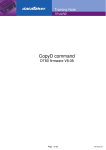
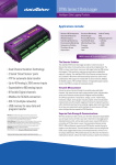
Vibration Wire Support in detail
The GeoLoggers generate a 'current pulse' to excite or 'pluck' the wire in the vibrating
wire gauge. Immediately following excitation, the resonant frequency of the vibrating
wire is measured. The advantage of the plucking pulse method is that a fixed pulse is
able to stimulate a wide range of gauges. This greatly simplifies channel
programming for the user.
The balanced plucking pulse is approximately 200 µS long and up to 36 Volts in
amplitude. The pulse has a current source characteristic that provides automatic
cable length compensation.
The GeoLogger has a high gain low noise signal amplifier with transformer coupling
on the input.
The amplified signal is filtered using band pass filters (500Hz to 5KHz) and a phase
lock loop to reduce frequency noise before the frequency is measured by a precision
frequency counter. Signals of the order of tens of microvolts can provide useful
readings.
Transformer coupling ensures very high common mode rejection, a characteristic
that is needed to reject 50/60 Hz mains noise and other interfering noise. A block
diagram of the pulse pluck method is illustrated below (Fig. 8.)
Figure 8 Block diagram of Vibrating Wire components
Page 6 of 14 TN-09RD-A4
Training Note
TR-09RD
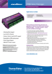
Connecting Vibrating wire strain gauges
Differential Inputs
The preferred method for connecting vibrating wire strain gauges to the GeoLogger is
differential connection, where the sensor is connected between the + and – or the *
and # terminals of the GeoLogger analog input channels.
Figure 9 Wiring for independent differential inputs
Single ended inputs
Vibrating wire strain gauges can also be connected to the GeoLogger as single
ended analog inputs. The signal from the sensor is connected between the +ve, –ve
terminal, and Analog Return terminal. Single ended connection for vibrating
or
wire strain gauges is illustrated in Figure 10 below
✴
Figure 10 Wiring for single ended inputs
The connection of vibrating wire strain gauges as single ended inputs referenced to
Analog Return is best used where
1.
cable lengths are relatively short (< 100 meters)
2.
vibrating wire strain gauges have good sensitivity
Because of the great range in vibrating wire strain gauge sensitivity, it is difficult to
predict the operating limits. It is suggested that where cable lengths are in excess of
100 meters, a test be conducted with the gauges to be deployed. Single ended
connection of vibrating wire strain gauges allows up to three sensors to be connected
to each analog input channel, and up to 15 sensors to be connected to a DT80G
GeoLogger or up to 48 sensors on the DT85G GeoLogger.
The number of sensors can be increased by using the CEM20 channel expansion
module on Series 2 DT80G or DT85G dataTaker data loggers.
Page 7 of 14 TN-09RD-A4
Training Note
TR-09RD
Measuring Gauge Temperature
Most vibrating wire strain gauges are sensitive to temperature fluctuations. Where a
vibrating wire strain gauge temperature is likely to change significantly, the gauge
temperature should be measured.
The vibrating wire strain gauge temperature can be measured using IC temperature
sensors, RTDs or thermistors supported by the GeoLogger.
Depending on the internal wiring of the vibrating wire strain gauge, it is often possible
to measure the vibrating wire frequency, and a resistive temperature sensor
(thermistor), on a single analog input channel.
If the sensor is fitted with an internal 2 wire thermistor then the thermistor must be
wired between the * and # terminals while the vibrating wire gauge can be connected
as a differential input. (Fig. 11.)
Figure 11 Wiring for thermistor and differential input
Grounding of cable shielding.
A shielded signal cable is recommended. Shielded wiring will reduce the potential
risk of electrical noise. The preferred shield connection point is either one of the
GeLlogger digital ground (D GND) terminals, a case ground terminal strip or the
ground point on either end of the DT80 range end plates (Refer Fig 12.)
Figure 12 DT80 range dataTaker showing grounding point (Silver screw)
Page 8 of 14 TN-09RD-A4
Training Note
TR-09RD
Typical Calculations
The output from VWSG sensors and the FW channel type is in Hz and need to be
converted into engineering units.
The examples provide are based on real sensors but the exact mathematics for
converting frequency to engineering units will be defined by the manufacturer of the
sensor. Please refer to the manufacturer’s literature for how to convert the sensor
output to engineering units.
dEX Example - Strain Gauge.
Strain Calculation
In this example the mathematics required to convert from frequency is stated on the
supplies data sheet as
MicroStrain = GF * (R1^2 – Rz ^2)
Where;
GF = Gauge Factor is 0.0006789
R1 = Current frequency reading
Rz = Zero frequency reading when gauge was installed is 1000 Hz
The steps required are;
1.
Configure the DT80 range GeoLogger to read a vibrating wire sensor as
described in the quick start section of this document.
2.
Add a calculation channel by selecting “Add” -> “Calculation” from the menu
bar.
Figure 13 Adding a calculation
Page 9 of 14 TN-09RD-A4
Training Note
TR-09RD
3.
In the tree view give the channel a unique and meaningful name. To accept
the name click on the tick.
Figure 14 Adding a calculation name
4.
To access the calculation builder click in the blank text area next to
“Calculation =”
Figure 15 Accessing calculation builder
5.
Enter the required calculation.
Note: You can click on the items in the list to add them to the calculation.
Figure 16 Entering a calculation
6.
Enter the channel units ue in the “Display units”
Figure 17 Adding channel units
Page 10 of 14 TN-09RD-A4
Training Note
TR-09RD
Strain calculation with temperature compensation
Temperature correction for the gauge can also calculate. The formula will be as per
the manufacturer’s specification. But usually requires the temperature of the gauge
being recorded at time of installation. Knowing the temperature response of the
gauge, the strain variation due to temperature effects can be allowed for.
MicroStrain = GF * (R1^2 – Rz ^2)-((T1-Tz)*TF)
Where;
GF= Gauge Factor is 0.0006789
R1 = Current frequency reading
Rz = Zero frequency reading when gauge was installed is 1000 Hz
T1 = Current temperature reading
Tz = Zero Temperature reading (e.g 20 Deg C)
TF = Temperature correction factor (e.g. 11 microstrain per Deg C)
In addition the steps for required for the strain calculation a temperature (Usually a
thermistor) sensor needs to be added and the temperature correction added to the
strain calculation above
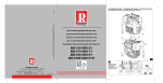
Tuning VWSG sensors
The DT80G and DT85G have a headphone jack (refer Fig 18) on the back of the
data logger which allows the operator to listen to the performance of the vibrating
wire sensor with standard head phones. The audio output is very useful if problems
when noise or damaged sensors are encountered.
Figure 18 DT85G with head phones attached
Page 11 of 14 TN-09RD-A4
Training Note
TR-09RD
To listen to the sound of a single gauge the following parameters and switch should
be set to;
P62=1 hold last channel open.
P21=1 keep analog section powered after measurement.
/k Turn off house keeping.
Then send the command to read the gauge. (Be sure to restore the setting when
finished)
A VWSG should have a crisp clean ping that decays over a number of seconds.
If a clean pinging sound is not heard when the vibrating wire strain gauge is sampled,
then the following trouble shooting guide will help diagnose the problem
1.
2.
3.
4.
5.
If there is only random noise, check the channel type, wiring and resistance.
The resistance measurement should be stable and not show long term drift.
If a ping can be heard but it is faint or buried in random noise, then the cable
is too long or is "leaky", or the gauge sensitivity is too low.
If the ping is not clean and pure, then the gauge is possibly faulty. The gauge
may have been mechanically damaged during installation.
If you can hear a low frequency hum, then electrical noise pick is a problem.
If the gauge is placed near a transformer, electric motor, high current power
cables, etc, then relocate or reorient the gauge for minimum pickup. Ensure
that the cable is shielded to prevent capacitive pickup.
In some cases performance may be improved by changing the default values of the
dataTaker channel factor and measurement delay.
Figure 19 Measurement delay and sample period
Page 12 of 14 TN-09RD-A4
Training Note
TR-09RD
Measurement Timing
When an FW channel is evaluated, the measurement process is as follows:
1.
The pluck circuit begins charging. The MD timer starts here also.
2.
After about 100ms, the pluck circuit releases its energy in the form of a
narrow high voltage pulse. Inside the sensor this causes the wire to start vibrating.
The resonant frequency will typically be in the range 500-5000Hz.
3.
Once the pluck is complete (about 0.2ms), the DT80G disconnects the pluck
circuit and begins listening to the sensor. Inside the sensor the wire's vibrations are
sensed and a corresponding electrical signal is generated.
4.
Over the next 100-200ms the DT80G's phase locked loop (PLL) locks on to
the fundamental frequency and filters out noise and harmonics. During this time the
amplitude of the signal gradually decays as wire’s vibrations decay.
5.
Once the MD timer expires the DT80G will begin measuring the frequency of
the filtered signal.
6.
Once the required sample period (gate time) has elapsed, the DT80G reports
the measured frequency value. It is important that the measurement delay is set such
that the incoming signal is stable and of adequate amplitude for the duration of the
measurement period. The default value is suitable for most gauges, but in some
cases it may need adjustment.
Optimizing sample measurement
If a strong and clear signal is heard, but the frequency measurements are unstable
(variations of 10-20Hz or more) then there may be strong harmonics present in the
gauge's vibration. Because harmonics usually decay faster than the fundamental, it
will often help to increase the MD setting. This will mean that the actual frequency
measurement phase starts later, at which point the amplitude of the harmonics
should be less. If the measurement delay is increased too much, however, the overall
signal amplitude may decay below the noise level.
On the other hand if the signal is week then reducing the measurement delay and
reducing the sample period will assist in tuning the circuit to optimize the reading.
If the signal is clear but decays rapidly then the default MD setting may in fact be too
long – by the time the measurement completes the signal has decayed to nothing.
Some trial and error may be required to find optimal settings. The recommended
procedure is as follows. For each step perform several measurements in order to
gauge the stability of the readings.
1.
Start with minimum values for measurement delay and sample period, e.g.
1FW(MD150,30)
2.
Increase the MD setting in, say, 20ms steps until stable readings are
obtained, then go one step further.
3.
Further improvement can usually be obtained by progressively increasing the
sample period so that the frequency is measured over a longer time interval. If this is
increased too far however then the signal amplitude will descend into the noise and
readings will get rapidly worse.
Page 13 of 14 TN-09RD-A4
Training Note
TR-09RD
Programming the DT80G data logger
DeTransfer / WEB UI example (Differential Inputs).
Enter the following dataTaker code into the send window of DeTransfer or the data
logger WEB UI command send pane and send to the data logger.
Code example 1:
Vibrating wire strain gauge with strain calculation
BEGIN"VWGS"
'Sample Vibrating wire strain gauge.
RA"Schedule_1"("b:",ALARMS:OV:100KB:W60,DATA:OV:1MB)5S
LOGONA
1FW("VW Gauge 1 reading~Hz",LM,MD350,200)
CALC("Strain Gauge 1~ue",LM)=0.0006789*(&"VW Gauge 1 reading"^21000^2)
END
Code example 2:
Vibrating wire strain gauge with strain calculation
BEGIN"VWGS"
'Sample Vibrating wire strain gauge with temperature compensation.
RA"Schedule_1"("b:",ALARMS:OV:100KB:W60,DATA:OV:1MB)5S
LOGONA
1FW("VW Gauge 1 reading~Hz",LM,MD350,200)
1*YS01(I,"VW Gauge 1 Temp~degC",LM,NA)
CALC("Strain Gauge 1~ue",LM)=0.0006789*(&"VW Gauge 1 reading"^21000^2)-11*(&"VW Gauge 1 Temp"-23)
END
For customer service, call 1300-735-292
To fax an order, use 1800- 067- 639
Visit us online: www.thermofisher.com.au
©2010 Thermo Fisher Scientific Australia Pty Ltd. All rights reserved. A.B.N. 52 058 390 917
Page 14 of 14 TN-09RD-A4