1
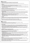
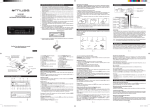
User Manual
English
Recon & Tora User Manual
Recon & Tora User Manual
recon sl, xc, 327, 335 / tora 289, 302
English
recon race, 351 / tora 318
E
E
E
H
C
E
H
C
J
F
F
F
G
G
J
F
G
G
K
K
D
A
B
D
I
A
B
A
A
A
B
B
I
A
B
B
A. Rebound Assembly / Baugruppe für Zugstufenregelung / Conjunto de Rebote / Assemblage de Rebond / Gruppo di Ritorno /
Bewegingscontrole Terugverings / Unidade de Recuperação /
/
A. Rebound Assembly / Baugruppe für Zugstufenregelung / Conjunto de Rebote / Assemblage de Rebond / Gruppo di Ritorno /
Bewegingscontrole Terugverings / Unidade de Recuperação /
/
B. Rebound Adjuster / Zugstufen-Einsteller / Ajustador del Rebote / Molette de Régalge du Rebond / Regolatore del Ritorno /
Terugveringsknop / Reulador de Recuperação /
/
B. Rebound Adjuster / Zugstufen-Einsteller / Ajustador del Rebote / Molette de Régalge du Rebond / Regolatore del Ritorno /
Terugveringsknop / Reulador de Recuperação /
/
C. Air Valve / Ventil / Válvula de aire / Valve à air / Valvola dell’aria / Luchtventiel / Válvula de ar /
C. Air Valve / Ventil / Válvula de aire / Valve à air / Valvola dell’aria / Luchtventiel / Válvula de ar /
/
/
D. Solo Air Piston / Solo Air-Kolben / Pistón Solo Air / Piston Solo Air / Pistone Solo Air / Solo Air-zuiger / Pistão de Solo Air /
/
D. Solo Air Piston / Solo Air-Kolben / Pistón Solo Air / Piston Solo Air / Pistone Solo Air / Solo Air-zuiger / Pistão de Solo Air /
/
E. Optional PopLoc Adjust Remote / Optional Fernbedienung für PopLoc-Einstellung / Mando a Distancia de Ajuste PopLoc
(opcional) / Réglage Distant PopLoc en Option / Regolazione PopLoc Remote Opzionale / Optionele PopLoc-Afstelling op Afstand /
Regulação Remota PopLoc (opcional) /
/
E. Optional PopLoc Adjust Remote / Optional Fernbedienung für PopLoc-Einstellung / Mando a Distancia de Ajuste PopLoc
(opcional) / Réglage Distant PopLoc en Option / Regolazione PopLoc Remote Opzionale / Optionele PopLoc-Afstelling op Afstand /
Regulação Remota PopLoc (opcional) /
/
F. Lockout Adjuster / Entsperrsystem-Einsteller / Ajustador de Bloqueo / Réglage du Blocage / Regolatore del Blocco /
Entsperrsystem-Einsteller / Regulador de Bloqueio /
/
F. Compression Adjuster / Druckstufen-Einsteller / Ajustador de la Compresión / Régleur de Compression / Regolatore della
Compressione / Compressieknop / Reulador de Compressão /
/
G. TurnKey Lockout / TurnKey-Entsperrsystem / Bloqueo del Sistema TurnKey / Blocage TurnKey / Blocco TurnKey (a Chiave) /
TurnKey Lockout (Gebruisklare Uitschakeling) / BLoqueio Turnkey /
/
G. Motion Control Assembly / Motion Control-Baugruppe / Conjunto Motion Control / Système Motion Control / Gruppo Motion
Control / Motion Control-montage / Unidad de Motion Control /
/
H. U-Turn Knob / U-Turn-Einstellknopf / Mando de Ajuste del U-Turn / Bouton U-Turn / Pomello U-Turn / U-Turn Afstelknop / Botão
de U-Turn /
/
H. U-Turn Knob / U-Turn-Einstellknopf / Mando de Ajuste del U-Turn / Bouton U-Turn / Pomello U-Turn / U-Turn Afstelknop / Botão
de U-Turn /
/
I. U-Turn Coil Spring / U-Turn-Schraubenfeder / Muelle Hilicoidal U-Turn / Ressort Hélicoïdal U-Turn / Molla Elicoidale U-Turn / UTurn springveer / Amortecedor de Mola de U-Turn /
/
I. U-Turn Coil Spring / U-Turn-Schraubenfeder / Muelle Hilicoidal U-Turn / Ressort Hélicoïdal U-Turn / Molla Elicoidale U-Turn / UTurn springveer / Amortecedor de Mola de U-Turn /
/
J. Preload Adjuster / Einstellknopf für Federvorspannung / Caperuza ajustadora de Precarga / Bouton de Réglage de la Préchare /
Manopola di Regolazione del Precarico / Knop Instelling Voorbelasting / Botão de Ajuste de Precarregamento /
/
J. Preload Adjuster / Einstellknopf für Federvorspannung / Caperuza ajustadora de Precarga / Bouton de Réglage de la Préchare /
Manopola di Regolazione del Precarico / Knop Instelling Voorbelasting / Botão de Ajuste de Precarregamento /
/
K. Coil Spring / Schraubenfeder / Muelle Helicoidal / Ressort Hélicoïdal / Molla elicoidale / Springveer / Mola do Amortecedor /
/
K. Coil Spring / Schraubenfeder / Muelle Helicoidal / Ressort Hélicoïdal / Molla elicoidale / Springveer / Mola do Amortecedor /
/
©SRAM Corporation • 2007
95-4312-834-000 Rev D
English
Recon & Tora User Manual
Recon & Tora User Manual
English
Congratulations!
Fork Installation
You have the best in suspension components on your bicycle! This manual contains important
information about the safe operation and maintenance of your fork. To ensure that your RockShox fork
performs properly, we recommend that you have your fork installed by a qualified bicycle mechanic. We
also urge you to follow our recommendations to help make your riding experience more enjoyable and
trouble-free.
It is extremely important that your RockShox fork is installed correctly by a qualified bicycle mechanic.
Improperly installed forks are extremely dangerous and can result in severe and/or fatal injuries.
1.
i m p o r ta n t
warning
consumer safety information
1. The fork on your bicycle is designed for use by a single rider, on mountain trails, and
similar off-road conditions.
DO NOT ADD THREADS TO ROCKSHOX THREADLESS STEERERS
THE STEERER TUBE CROWN ASSEMBLY IS A ONE-TIME PRESS FIT.
REPLACEMENT OF THE ASSEMBLY MUST BE DONE TO CHANGE THE
LENGTH, DIAMETER OR HEADSET TYPE (THREADED OR THREADLESS).
2. Before riding the bicycle, be sure the brakes are properly installed and adjusted.
Use your brakes carefully and learn your brakes’ characteristics by practicing your
braking technique in non-emergency circumstances. Hard braking or improper use
of the front brake can cause you to fall. If the brakes are out of adjustment, improperly
installed or are not used properly, the rider could suffer serious and/or fatal injuries.
3. Your fork may fail in certain circumstances, including, but not limited to, any condition
that causes a loss of oil; collision or other activity bending or breaking the fork’s
components or parts; and extended periods of non-use. Fork failure may not be visible.
Do not ride the bicycle if you notice bent or broken fork parts, loss of oil, sounds of
excessive topping out, or other indications of a possible fork failure, such as loss
of shock absorbing properties. Instead, take your bike to a qualified dealer
for inspection and repair. In the event of a fork failure, damage to the bicycle or
personal injury may result.
4. Always use genuine RockShox parts. Use of aftermarket replacement parts voids the
warranty and could cause structural failure to the shock. Structural failure could result in
loss of control of the bicycle with possible serious and/or fatal injuries.
5. Use extreme caution not to tilt the bicycle to either side when mounting the bicycle to a
carrier by the fork drop-outs (front wheel removed). The fork legs may suffer structural
damage if the bicycle is tilted while the drop-outs are in the carrier. Make sure the fork is
securely fastened down with a quick release. Make sure the rear wheel is fastened down
when using ANY bike carrier that secures the fork’s drop-outs. Not securing the rear can
allow the bike’s mass to side-load the drop-outs, causing them to break or crack. If the
bicycle tilts or falls out of its carrier, do not ride the bicycle until the fork is properly
examined for possible damage. Return the fork to your dealer for inspection or call
RockShox if there is any question of possible damage (See the International Distributor
List). A fork leg or drop-out failure could result in loss of control of the bicycle with
possible serious and/or fatal injuries.
6. Forks designed for use with ‘v’-style brakes: only mount cantilever-type brakes to the
existing brake posts. Forks with hangerless style braces are only designed for V-style or
hydraulic cantilever brakes. Do not use any cantilever brake other than those intended
by the brake manufacturer to work with a hangerless brace. Do not route the front brake
cable and/or cable housing through the stem or any other mounts or cable stops. Do not
use a front brake cable leverage device mounted to the brace. Forks designed for
use with disc-style brakes: follow the brake manufacturer’s installation instruction for
proper installation and mounting of the brake caliper.
7. Observe all owner’s manual instructions for care and service of this product.
ROCKSHOX FORKS ARE DESIGNED FOR COMPETITIVE OFF-ROAD RIDING AND DO
NOT COME WITH THE PROPER REFLECTORS FOR ON-ROAD USE. YOUR DEALER
SHOULD INSTALL PROPER REFLECTORS TO MEET THE CONSUMER PRODUCT
SAFETY COMMISSIONíS (CPSC) REQUIREMENTS FOR BICYCLE STANDARDS IF
THE FORK IS GOING TO BE USED ON PUBLIC ROADS AT ANY TIME.
95-4312-834-000 Rev D
Remove the existing fork from the bicycle and the crown race from the fork. Measure the length of
the fork steerer tube against the length of the RockShox steerer tube. The RockShox steerer tube
may need cutting to the proper length. Make sure there is sufficient length to clamp the stem (refer
to the stem manufacturer’s instructions).
DO NOT REMOVE OR REPLACE THE STEERER TUBE. THIS COULD RESULT
IN THE LOSS OF CONTROL OF THE BICYCLE WITH POSSIBLE SERIOUS
AND/OR FATAL INJURIES.
.
Install the headset crown race (29.9mm for 1 1/8” steerers) firmly against the top of the fork crown.
Install the fork assembly on the bike. Adjust the headset until you feel no play or drag.
3.
Install the brakes according to the manufacturer’s instructions and adjust brake pads properly. Use
the fork only with disc style brakes mounted through the provided mounting holes. Do not use any
cantilever brake other than those intended by the brake manufacturer to work with a hangerless
brace.
4.
Forks designed for standard quick releases: adjust the front wheel quick release to clear the
dropout’s counter bore. The quick release nut must be tightened after the wheel is properly seated
into the dropout’s counter bore. Make sure four or more threads are engaged in the quick release
nut when it is closed. Orient the quick release lever in front of and parallel to the lower tube in the
locked position.
5.
Keep in mind tire clearance as you choose tires. Maximum size is:
Fork
Max Tire Size (installed)
Recon
2.5”
Tora
2.5”
Be sure to check this diameter whenever you change tires. To do this, remove air pressure and
compress the fork completely to make sure at least 5 mm of clearance exists between the top of the
tire and the bottom of the crown. Exceeding maximum tire size will cause the tire to jam against the
crown when the fork is fully compressed.
PopLoc Remote Installation
The PopLoc Remote Lockout lever allows the rider to control the movement of their suspension fork
without removing their hands from the handlebars. Specific left and right PopLocs are available. If
needed, remove the grip, brake lever, and shifter from the handlebar. If you are unfamiliar with the
removal of these items, please consult the manufacturer’s instructions.
1.
Slide the Poploc onto the handlebar.
.
Re-install the shifter, brake lever, and grip on the handlebars. If you are unfamiliar with the
installation of these items, please consult the manufacturer’s instructions. Always adhere to the
recommended torque specifications for these items.
3.
Position the PopLoc as desired on the handlebar and tighten the clamp bolt to 20 in-lb (2.25 Nm)
©SRAM Corporation • 2007
English
Recon & Tora User Manual
4.
Forks with PopLoc Adjust: Turn the blue compression adjustment dial counterclockwise until it stops.
5.
Press the release button on the PopLoc.
6.
Install the cable in the PopLoc.
7.
Install the cable into the housing.
8.
Feed the cable and housing into the cable stop on the fork crown.
9.
Gently pull on the cable and align it with the groove in the rotating cam of the Motion Control
damper.
Recon & Tora User Manual
English
coil spring tuning
Changing the Spring Rate
Spring rate is the amount of force needed to compress a spring one inch. Changing your fork’s coil
spring for a spring of a higher or lower rate will alter the overall feel of your fork. Higher spring rates
make the fork feel more “stiff”, while lower spring rates make the fork more “supple”. Contact your local
RockShox dealer to order replacement springs.
10. Tighten the cable fixing bolt on the rotating cam to 8 in-lb (.9 Nm)
note: for pushloc installation or pushloc with matchmaker installation, please refer to the instructions
on our website at www.rockshox.com.
note: when decreasing travel (see
“u-turn travel adjust”), you increase the spring rate.
travel adjustments
important: stop turning the u-turn adjuster knob after you’ve reached maximum travel. turning the knob
past this point may cause damage to the u-turn feature.
Performance Tuning
note: ensure the fork is compressed once after sitting for more than a day and in ‘open’ position before
RockShox forks can be tuned for your particular weight, riding style, and terrain.
Coil U-Turn Travel Adjust
U-Turn forks offer 45mm of travel adjustment (Recon/Tora: 85 to 130mm). To determine the travel on
your fork, use the travel gradients on the upper tube (except Tora). Turning the U-Turn adjuster knob
counterclockwise increases travel. Each turn increases or decreases the travel by 7.5 mm.
travel adjustment.
settinsg sag
RockShox forks are designed to sag when you are sitting on your bike. Sag is the compression of the
fork caused by the rider’s weight. Proper sag allows the front wheel to follow the contour of the terrain
as you ride.
To measure sag, set the fork to maximum travel. Install a zip tie on the upper tube of the fork flush
against the wiper seal. Sit on the bike with normal riding apparel. Step off the bike, and measure the
distance between the wiper seal and the zip tie. This is your sag. The sag should be between 15 and
25 percent of maximum travel. If you’re unable to achieve optimum sag you may need to change the
fork’s air pressure (Solo Air), spring (U-Turn Coil) or preload (Coil).
Use the tuning information below to assist in proper set up of your fork.
PRELOAD ADJUSTMENT
• Turning the adjuster clockwise increases spring preload (i.e., stiffening the spring), decreasing sag.
• Turning the adjuster counterclockwise decreases spring preload, increasing sag.
air spring tuning
Solo Air
The positive and negative air chambers with these forks fill simultaneously from a single valve. The air
spring is designed so the pressure in the two separate chambers equalizes as air is added, simplifying
setup and providing a balanced ride.
Changing Travel
To change the travel of your fork (Recon and Tora: 80, 100 or 130) you must perform a full service on
your fork. To obtain service information and instructions, visit our website at www.rockshox.com or
contact your local RockShox dealer or distributor.
rebound damping
External Rebound Adjustment
Rebound damping controls the speed at which a fork returns to its full extension following compression.
Located at the bottom of the right fork leg is the rebound adjuster knob. Turning the adjuster in the
direction indicated by the “rabbit” on the rebound speed decal decreases rebound damping, causing
the fork to return to full extension faster. Turning the adjuster in the direction indicated by the “turtle”
increases rebound damping, slowing the return of the fork to full extension.
note: excessive rebound damping will cause the fork to
“pack up” over successive bumps, reducing travel
“topping out”
or kicking back. this allows your fork to follow the contours of the trail, maximizing stability, traction
and control.
and causing the fork to bottom out. set your fork to rebound as fast as possible without
Setting Solo Air
Remove the air cap on the air valve located on the rider’s left side of the fork crown by turning
counterclockwise. Using the air chart below as a guideline, inflate the air chambers to the desired
pressure.
motion control damping system
(recon 351, race and tora 318)
note: when adding air to the fork, a user may see a sudden drop in the air pressure reading on their shock
collect above the motion control damper assembly. upon returning the bicycle/fork to a normal riding
pump. this is normal and indicates that the negative air chamber has opened and the pressure between the
position, initial performance of the motion control system may be less than optimal. to quickly return the
important: when storing a bicycle or fork upside-down or on its side, oil sealed in the upper tube can
chambers has equalized. the user should continue to add air to the fork until the predetermined pressure
fork to proper performance, return the fork to ‘open’ position and cycle the fork through its travel
is met.
20 times.
Recon (327, 335, 351)
Solo Air
Recon (Race, SL, XC)
Solo Air
Tora
<140 (63kg)
80-100psi
50-70psi
90-110psi
140-160 (63-72kg)
100-120psi
70-85psi
110-125psi
160-180 (72-81kg)
120-140psi
85-100psi
125-140psi
180-200 (81-90kg)
140-160psi
100-120psi
140-160psi
180+psi
135+psi
175+psi
Rider Weight
>220 (99kg)
Solo Air
95-4312-834-000 Rev D
10-
for information on returning your fork to ‘open’ position, keep reading!
The Motion Control Damping system allows riders to quickly adjust the feel and performance of their
suspension to match riding conditions without requiring pumps or tools. This system provides for wideranging control of compression and rebound damping as well as ‘Lock’ threshold sensitivity. Proper
setup of the Motion Control Damping system provides a range of options for efficient yet comfortable
performance. The instructions below describe setup and operation for both crown and remote activated
forks.
©SRAM Corporation • 2007
English
Recon & Tora User Manual
Recon & Tora User Manual
English
‘Open’ Compression (Fig. 1)
In the ‘Open’ position, the Motion Control Damping system allows for maximum compliance and fork
movement. The ‘Open’ position provides ultimate control and comfort on even the roughest terrain. To
return your fork to the ‘Open’ position:
• For forks with the crown-mounted blue compression adjuster, rotate the adjuster fully
counterclockwise.
• For PopLoc equipped forks, press the “unlock” release button on the remote (as indicated by the
open padlock icon on the button).
Fig. 2
Compression Adjustment (Fig. 3)
Some fork models also feature adjustable compression damping. Increased compression decreases
fork movement in the ‘Open’ position. Compression adjustment can be used to help combat brake dive
and “squatting” under hard cornering.
For crown activated forks, compression damping increases to ‘Lock’ as the crown-mounted actuator
rotates 90 degrees clockwise. Position the actuator anywhere within the range from ‘Open’ to ‘Lock’ to
suit the desired level of compression damping.
Fig. 1
‘Lock’ Compression (Fig. 2)
In the ‘Lock’ position, the Motion Control system allows for a small amount of controlled fork movement.
This movement enables the front tire to track the terrain without deflecting off obstacles, allowing for
better traction and steering control when compared to a complete lockout system. To activate the ‘Lock’,
turn the crown-mounted blue compression adjuster full clockwise or press forward on the PopLoc
Remote lever located on the handlebar.
Forks equipped with the PopLoc Adjust provide compression damping adjustment for the ‘Open’ position.
Turning the blue adjuster on the PopLoc adjust clockwise increases compression damping for the ‘Open’
position. The PopLoc lever features gradients to help illustrate the current level of compression. Eight
complete turns of adjustment are provided.
tip: adjusting compression on forks equipped with poploc adjust is best done with the fork in ‘lock’
position.
note: the compression setting does not adversely effect your fork’s performance over high speed impacts.
95-4312-834-000 Rev D
©SRAM Corporation • 2007
English
Recon & Tora User Manual
TurnKey Lockout
Turning the compression adjuster on the PopLoc Adjust
sets how far the lever returns from 'Lock' toward the 'Open'
position. This adjustment changes the amount of
compression damping found in the 'Open' position.
Fork movement
Select compression damping
between 'Open' and 'Lock'
English
Off = maximum fork movement
On = minimum fork movement
On
Off
TurnKey two position
' On - Off ' lockout
Fork movement
compression range
Recon & Tora User Manual
Remote
Compression
Adjuster
Off
PopLoc Remote
(optional)
On
Off position
On position
Crown mounted adjuster
Crown mounted adjuster
PopLoc Remote
PopLoc Adjust Remote
PopLoc Adjust Remote
Fig. 4
Maintenance
Fig. 3
To maintain the high performance, safety, and long life of your fork, periodic maintenance is required. If
you ride in extreme conditions, maintenance should be performed more frequently.
TurnKey Lockout System (fig.4)
(RECON 335, SL AND TORA 302)
note: we recommend this service be performed by a qualified bicycle mechanic. to obtain service
information or instructions, visit our website at www.rockshox.com or contact your local rockshox
important: when storing a bicycle or fork upside-down or on its side, oil sealed in the upper tube can
dealer or distributor.
collect above the turnkey assembly. upon returning the bicycle/fork to a normal riding position, initial
performance of the turnkey system may be less than optimal. to quickly return the fork to proper
performance, return the fork to ‘open’ position and cycle the fork through its travel
10-20 times.
Torque Tightening Values
for
information on returning your fork to ‘open’ position, keep reading!
The TurnKey lockout system offers a two position ‘on/off’ lockout. Using either the crown mounted
adjuster or an optional PopLoc Remote, the rider is able to choose between maximum compliance and
fork movement (when the lockout is ‘off’) and minimal compliance and fork movement (when the lockout
is ‘on’).
The TurnKey lockout is ‘off’ when either the crown mounted adjuster (or remote spool) is in the full
counterclockwise position or the PopLoc Remote lever returns to the ‘unlock’ position. The lockout turns
‘on’ as the rider rotates the crown mounted adjuster clockwise or by pressing forward on the optional
Poploc Remote located on the handlebar.
Top Caps
65 in-lb (7.3 Nm)
Brake Posts
80 in-lb (9.0 Nm)
Shaft Bolts
60 in-lb (6.8 Nm)
PopLoc Remote Handlebar Clamp Bolt
20 in-lb (2.3 Nm)
PopLoc Remote Cable Fixing Bolt
8 in-lb (1.0 Nm)
U-Turn Adjuster Knob Screw
12 in-lb (1.4 Nm)
note: when the turnkey lockout is ‘on’ and the fork encounters a considerable input force, the lockout
will ‘blowoff’ and allow the fork to move into its travel to absorb the input force. the fork will return
and remain in its lockout state until either another force is encountered or the rider turns the adjuster
to the ‘off’ position.
10
95-4312-834-000 Rev D
©SRAM Corporation • 2007
11
English
Recon & Tora User Manual
All 32mm XC &
All Mountain Air Forks
All 32mm XC &
All Mountain Coil Forks
Clean dirt and debris from upper tubes
E
E
Inspect upper tubes for scratches
E
E
Lubricate dust seals/tubes
10
10
Check to caps, brake posts, and shaft bolts for proper
torque
25
25
SERVICE INTERVALS
Check air pressure
E
*
Remove lowers, clean/inspect bushings, and change
oil bath
50
50
Change oil in Motion Control System
100
100
Clean and lubricate Air U-Turn/Dual Air/Air Assist
assembly/Solo Air
50
*
*
100
50
50
Clean and lubricate coil spring or coil U-Turn spring
assembly
Clean and lubricate PopLoc cable and housing
notes:
e
= every ride
numeric values represent hours of riding time.
increase service intervals based on rider weight, aggressive riding style/conditions, inclement weather and racing.
Recon & Tora User Manual
English
SRAM Corporation Warranty
Extent of Limited Warranty
SRAM warrants its products to be free from defects in materials or workmanship for a period of two
years after original purchase. This warranty only applies to the original owner and is not transferable.
Claims under this warranty must be made through the retailer where the bicycle or the SRAM component
was purchased. Original proof of purchase is required.
Local law
This warranty statement gives the customer specific legal rights. The customer may also have other
rights which vary from state to state (USA), from province to province (Canada), and from country to
country elsewhere in the world.
To the extent that this warranty statement is inconsistent with the local law, this warranty shall be
deemed modified to be consistent with such law, under such local law, certain disclaimers and limitations
of this warranty statement may apply to the customer. For example, some states in the United States
of America, as well as some governments outside of the United States (including provinces in Canada)
may:
a.
Preclude the disclaimers and limitations of this warranty statement from limiting the statutory
rights of the consumer (e.g. United Kingdom).
b.
Otherwise restrict the ability of a manufacturer to enforce such disclaimers or limitations.
Limitations of Liability
To the extent allowed by local law, except for the obligations specifically set forth in this warranty
statement, In no event Shall SRAM or its third party supplies be liable for direct, indirect, special,
incidental, or consequential damages.
Limitations of Warranty
This warranty does not apply to products that have been incorrectly installed and/or adjusted according
to the respective SRAM technical installation manual. The SRAM installation manuals can be found
online at www.sram.com or www.rockshox.com.
This warranty does not apply to damage to the product caused by a crash, impact, abuse of the product,
non-compliance with manufacturers specifications of usage or any other circumstances in which the
product has been subjected to forces or loads beyond its design.
This warranty does not apply when the product has been modified.
This warranty does not apply when the serial number or production code has been deliberately altered,
defaced or removed.
This warranty does not apply to normal wear and tear. Wear and tear parts are subject to damage as a
result of normal use, failure to service according to SRAM recommendations and/or riding or installation
in conditions or applications other than recommended.
Wear and tear parts are identified as:
• Bushings
• Dust seals
• Air sealing o-rings
• Glide rings
• Rubber moving parts.
• Foam rings
• Rear shock mounting hardware • Upper tubes (stanchions)
and main seals
• Stripped threads/bolts (aluminium, • Brake sleeves
titanium, magnesium or steel)
• Brake pads
• Chains
• Sprockets
• Cassettes
• Shifter and brake cables (inner and outer) • Handlebar grips
• Shifter grips
• Jockey wheels
• Disc brake rotors
• Tools
This warranty shall not cover damages caused by the use of parts of different manufacturers.
This warranty shall not cover damages caused by the use of parts that are not compatible, suitable
and/or authorised by SRAM for use with SRAM components.
12
95-4312-834-000 Rev D
©SRAM Corporation • 2007
13
95-4312-834-000, Rev. C
2007
1610 Garden of the Gods
Colorado Springs, CO 80907
Ride on open trails only
Leave no trace
Control your bicycle
Always yield trail
Never spook animals
Plan ahead