1
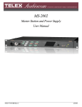
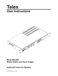
MS-2002
Master Station and Power Supply
User Manual
9350-7749-000 Rev E
December/2006
PROPRIETARY NOTICE
The product information and design disclosed herein were originated by
and are the property of Telex Communications, Inc. Telex reserves all
patent, proprietary design, manufacturing, reproduction, use and sales
rights thereto, and to any article disclosed therein, except to the extent
rights are expressly granted to others.
COPYRIGHT NOTICE
Copyright 2006 by Telex Communications, Inc. All rights reserved.
Reproduction, in whole or in part, without prior written permission from
Telex is prohibited.
WARRANTY NOTICE
See the enclosed warranty card for further details.
CUSTOMER SUPPORT
Technical questions should be directed to:
Customer Service Department
RTS/Telex Communications, Inc.
12000 Portland Avenue South
Burnsville, MN 55337 USA
Telephone: 800-392-3497
Fax: 800-323-0498
Factory Service: 800-553-5992
RETURN SHIPPING INSTRUCTIONS
Customer Service Department
Telex Communications, Inc. (Lincoln, NE)
Telephone: 402-467-5321
Fax: 402-467-3279
Factory Service: 800-553-5992
Please include a note in the box which supplies the company name,
address, phone number, a person to contact regarding the repair, the type
and quantity of equipment, a description of the problem and the serial
number(s).
SHIPPING TO THE MANUFACTURER
All shipments of product should be made via UPS Ground, prepaid (you
may request from Factory Service a different shipment method). Any
shipment upgrades will be paid by the customer. The equipment should
be shipped in the original packing carton. If the original carton is not
available, use any suitable container that is rigid and of adequate size. If
a substitute container is used, the equipment should be wrapped in paper
and surrounded with at least four (4) inches of excelsior or similar shockabsorbing material. All shipments must be sent to the following address
and must include the Proof of Purchase for warranty repair. Upon completion of any repair the equipment will be returned via United Parcel
Service or specified shipper, collect.
Factory Service Department
Telex Communications, Inc.
8601 East Cornhusker Hwy.
Lincoln, NE 68507 U.S.A.
Attn: Service
This package should include the following:
QTY
DESCRIPTION
PART
NUMBER
1
Power Cord Requirements
38109-668
1
Statement of Conformity
38109-675
1
Warranty
38110-390
1
User Manual
9350-7749-000
1
1/1/4” Face Plate, Right, Black
91607353-003
1
1/1/4” Face Plate, Left, Black
91607353-002
1
Power Cord
25040003-00
1
MS2002 Final Assembly
9010-7749-000
2
Rack Mount Bracket
9110-7353-000
Table
of
Contents
Chapter 1
Introduction .......................................................3
Description ........................................................3
Features .............................................................3
Chapter 2
Installation .........................................................5
Configuration Pre-check ...................................5
Headset Microphone Type
Selection DIP Switch ........................................7
Mic Kill Send Enable DIP Switch ....................7
Program Interrupt DIP Switches .......................7
Incoming Call Beep DIP Switches ....................7
Monaural or Binaural Operation
DIP Switches .....................................................8
Balanced Unbalance Switches ..........................8
Direct Program Listen
Enable/Disable Jumpers ....................................8
Mounting ...........................................................9
Connections .......................................................9
External Program Input and PA Output ............9
Cables ................................................................9
Chapter 3
Operation and Specifications ..........................17
Power-Up Check .............................................17
Test Tone .........................................................17
Sidetone Adjustment .......................................17
Voice-Activated Microphone
(Vox) Setup .....................................................18
Operation .........................................................19
Normal vs. Programming Mode ......................19
Volume Adjustment ........................................19
Receiving Calls ...............................................19
Call and Intercom Channel .............................19
Microphone Mute During Talk .......................20
All Talk ...........................................................20
Public Address (PA) ........................................20
Turning the Program Inputs ON and OFF ......20
Using Mic Kill ................................................20
Using Voice-Activated Microphone (Vox) .....21
Incoming Call Beep ON / OFF .......................21
Specifications ..................................................22
Quick Reference ..............................................25
CHAPTER 1
Introduction
Description
The MS-2002 is a complete 2-channel master station and system power supply (24 VDC, 2 Amps total power) in a single unit.
Simply plug it into any AC power outlet from 100 to 240 volts, add a microphone or headset, connect intercom stations to the
back panel, and you’re ready to communicate. It even has both 1-channel and 2-channel connectors, so you don’t have to add
a separate breakout box if you want to mix 1-channel and 2-channel stations. The MS-2002 fits in a standard 19-inch equipment rack and is 1 rack unit high. The basic MS-2002 can communicate with two intercom channels. This number can be
increased by connecting optional EMS-4001 Expansion Stations. Each EMS4001 adds four addition channels, and up to four
of these expansion stations can be connected for a total of eighteen channels.
Features
FIGURE 1.
MS-2002 Reference View.
3
Introduction
1.
Dynamic-Mic Headset Connector - Accepts headsets with monaural headphones and either a balanced or unbalanced
dynamic microphone.
2.
Panel Mic / Electret-Mic Headset Connector - Accepts an electret gooseneck microphone, such as the Telex Model
MCP-90-XX. The model MCP-90 series panel mic connector is a 1/4” stereo plug, with a threaded shaft for easy
installation.
3.
Volume Control - Adjusts headphone volume only.
4.
Vox Trimmers - Used with the voice-activated microphone feature. Separate trimmers adjust the voice activation level for
the headset and panel microphones.
5.
Headset and Panel Mic Keys - Used to manually activate either the headset or panel microphone, whichever is being used.
6.
All Talk Key - Used to talk to all stations that are listening on all channels. This includes both MS-2002 channels and all
channels of any connected EMS4001 Expansion Stations.
7.
PA Key - If the MS-2002 is connected to a public address system, this key may be used to talk over the public address
system.
8.
Mic Kill Key - Used to turn OFF the microphones on any intercom stations on a channel. Also used to activate the program
inputs and the audible beep feature for incoming calls.
9.
Intercom Talk Keys - Momentary or latching (hands-free) operation possible.
10.
Call Keys - Used to place calls on intercom channels and to indicate incoming calls.
11.
Intercom Listen Keys - Momentary or latching operation possible.
12.
Speaker Volume Control - The volume control adjusts the level to the front panel speaker. If an external speaker is used,
volume must be adjusted at the external speaker.
13.
Combine / Isolate Switch - This recessed, push-button switch lets you combine the audio signals of the two channels to
create a single audio channel where all users can intercommunicate. Or, you can isolate each channel to create two groups
of completely independent users. For normal operation, it should be set in the isolate position.
14.
Channel Status Indicators and Reset Push-buttons - The indicators are green for normal operation and red when there is an
overload or short circuit. The Reset push-button restores normal operation after the short-circuit or overload has been
located and fixed.
15.
Universal AC Power Input - The MS-2002 accepts any input power in the range of 100-240 VAD, 50/60 Hz.
16.
2-channel Intercom Cable Connectors - One male and one female XLR-6 connector for 2-channel operation with SS2002,
BP-2002, etc.
17.
Program Inputs Connector and Trimmers - Each intercom channel has its own program input and level adjust trimmer. The
program inputs may be turned ON or OFF via the front panel and they may be set to interrupt during talk, if desired.
18.
1-channel Intercom Cable Connectors - Two connectors are provided for each channel for loop-through connection of
1-channel intercom stations, such as the SS1002, BP1002, etc.
19.
PA Output - Connects to a public address system.
20.
Expansion Out Connector - Connects to an EMS4001 Expansion Station.
21.
Speaker Output Jacks - May be used with external, powered loudspeakers for monaural or binaural listening
configurations.
22.
Balanced / Unbalanced Selector Switches - The selector switches sets the MS-2002 for compatibility with either Audiocom
or Clear-Com® channel connector pin-outs, channel power requirements, and call signaling requirements. Both switches
must be in the same position.
4
CHAPTER 2
Installation
Configuration Pre-check
Before connecting the MS-2002 make sure it is properly configured for you intended usage. Figure 2 shows the locations of
the configuration switches. To access internal switches, remove three screws from the top cover and three screws from the
bottom portion of each side.
FIGURE 2.
Locations of Configuration Jumpers and Switches
5
Installation
Switch #
Description
Settings
Default
DIP SWITCH SW1 (INTERNAL)
On: Unbalanced
SW1-1
Headset Microphone Type
SW1-2
Call Signal Send, channel 1
SW1-3
Call Signal Receive, channel 1
SW1-4
Call Signal Send, channel 2
SW1-5
Call Signal Receive, channel 2
SW1-6
Mic Kill Signal Send
SW1-7
Program 2
SW1-8
Program 1
Off: Balanced
On: Enabled
Off: Disabled
On: Enabled
Off: Disabled
On: Enabled
Off: Disabled
On: Enabled
Off: Disabled
On: Enabled
Off: Disabled
On: Interrupt During Talk
Off: No Interrupt
On: Interrupt During Talk
Off: No Interrupt
Off
On
On
On
On
Off
Off
Off
BALANCED (BAL - UNBALANCED (UNBAL) OPERATION
BOTH SWITCHES MUST BE SET THE SAME
FACTORY DEFAULT IS BALANCED
Rear Panel
Audiocom or Clear-Com operation
Rear Panel
Audiocom or Clear-Com operation
Out: Balanced (Audiocom)
In: Unbalanced (Clear-Com)
Out: Balanced (Audiocom)
In: Unbalanced (Clear-Com)
Out (BAL)
Out (BAL)
DIP SWITCH SW3 (INTERNAL)
*SET ALL TO MONAURAL OR ALL TO BINAURAL
SW3-1
Incoming Call Beep
SW3-2*
Listen 1 to speaker 1 only
SW3-3
Incoming Call Beep, Speaker 1
SW3-4
Incoming Call Beep, Speaker 2
SW3-5
Listen 2 to Right Headphone
SW3-6
Listen 2 to Speaker 1
SW3-7
Listen 2 to Speaker 2
SW3-8
Listen 1 to Left Headphone
TABLE 1. Configuration
6
Switch Table
On: Disabled
Off: Enabled
On: Enabled (Binaural)
Off: Disabled (Monaural)
On: Enabled (SW3-1 must be OFF)
Off: Disabled
On: Enabled (SW3-1 must be OFF)
Off: Disabled
On: Enabled (Monaural)
Off: Disabled (Binaural)
On: Enabled (Binaural)
Off: Disabled (Monaural)
On: Enabled (Monaural)
Off: Disabled (Binaural)
On: Enabled (Monaural)
Off: Disabled (Binaural)
Off
Off
Off
Off
On
Off
On
On
Headset Microphone Type Selection DIP Switch
Headset Microphone Type Selection DIP Switch
SW1-1 applies only to a dynamic-mic headset connected to the dynamic-mic headset jack on the front panel. If the headset
specifications indicate the microphone type is balanced, or if you are unsure, leave this switch in the OFF (default) position. If
the specifications indicate an unbalanced microphone set SW1-1 to ON.
NOTE: For best results in noisy environments, a noise canceling (directional or cardioid) microphone is highly recommended.
This is especially true if you are using the Vox feature.
Mic Kill Send Enable DIP Switch
The MS-2002 can generate an inaudible signal which will turn OFF the microphones on all intercom stations on a channel (for
stations that detect this signal). This feature is useful, for example, when an unattended microphone has been left on and is
causing unnecessary noise on a channel. By default, Mic Kill is not enabled. To activate this feature set SW1-6 to the ON
position.
Program Interrupt DIP Switches
If you plan on using external program sources with the MS-2002, you have a choice of whether or not you want the program
audio to shut off on the intercom channel while you are talking. By default, program audio does not interrupt during talk. You
can change this as follows:
1.
For channel 1 program interrupt during talk, set SW1-7 to ON.
2.
For channel 2 program interrupt during talk, set SW1-8 to ON.
Incoming Call Beep DIP Switches
If call signal receive is enabled (switches SW1-3 and SW1-5), incoming calls will be indicated by red-flashing Call keys. An
optional beep tone can also be used. Internal switches enable the beep tone. You can then turn the beep tone ON or OFF via the
front panel during normal operation. Enable the beep tone as follows:
1.
Make sure the call signal receive DIP switches are ON (SW1-3 and SW1-5).
2.
For incoming call beep in a headset, set SW3-1 to OFF.
3.
For incoming call beep in speaker 1, set SW3-1 to OFF and SW3-3 to ON.
4.
For incoming call beep in speaker 2, set SW3-1 to OFF and SW3-4 to ON.
5.
The procedure to turn incoming call beep ON or OFF during operation can be found on page 21.
7
Installation
Monaural or Binaural Operation DIP Switches
The MS-2002 can be used with a single speaker or monaural headphones (single- or double-sided) for monaural operation. In
this case, all audio signals are combined and sent to the headphones and the front panel speaker. The combined signals also go
to the Speaker 1 jack on the back panel. The MS-2002 can also be used with two speakers for binaural operation. In this case,
channel 1 is sent to the Speaker 1 jack and channel 2 is sent to the Speaker 2 jack. Binaural headphone operation is not
supported.
For monaural operation with headphones or one speaker (factory default):
1.
Set SW3-2 to OFF.
2.
Set SW3-5 to ON.
3.
Set SW3-6 to OFF.
4.
Set SW3-7 to ON.
5.
Set SW3-8 to ON.
For binaural operation with two speakers:
1.
Set SW3-2 to ON.
2.
Set SW3-5 to OFF.
3.
Set SW3-6 to ON.
4.
Set SW3-7 to OFF.
5.
Set SW3-8 to OFF.
Balanced Unbalance Switches
Both of the BAL-UNBAL Switches on the back panel are set at the factory to the balanced (BAL) position for use with
Audiocom intercom channels. Set the switches to the unbalanced (UNBAL) position for use with a Clear-Com intercom
system.
Direct Program Listen Enable / Disable Jumpers
By default, each MS-2002 program input can be heard by all intercom stations that are listening on the corresponding intercom
channel. This includes the MS-2002. Program input routing to the intercom channels can be turned ON or OFF via the MS2002 speaker or headset. This lets the MS-2002 operator hear the program inputs even if they are not being routed to the
intercom channels. To disable direct program listening in the speaker or headset for one or more program inputs, reset the
appropriate jumper as shown in Table 2.
Jumper
Description
J3
Program 1 direct to Headset or Speaker
J4
Program 2 direct to Headset or Speaker
TABLE 2. Direct
8
Program Listen Enable / Disable Jumpers
Settings for Jumpers
Pins 2 & 3 Shorted: Enabled
Pins 1 & 2 Shorted: Disabled
Pins 2 & 3 Shorted: Enabled
Pins 1 & 2 Shorted: Disabled
Mounting
Mounting
The MS-2002 mounts in a standard 19-inch equipment rack and is 1 rack unit (RU) high. When mounting the MS-2002 install
the supplied black face plates on the appropriate side. The face plates should be mounted with the grooves on the top.
NOTE: You will have to perform the sidetone adjustment (page 17) after all components are connected. With the MS-2002
being rack mounted, you may not be able to access the sidetone trimmers. In this case, you can position the MS-2002 in the
rack and make all required connections. Then, adjust the sidetone trimmers before installing and tightening all rack mount
screws.
Connections
Refer to the following paragraphs, and the sample connection drawings shown in Figures 3 to 6.
External Program Input and PA Output
Connection for external program input and PA output are shown in Figure 6 on page 14, EMS4001 Expansion Station
Connection (Optional Component).
Refer to the EMS4001 User Instruction Manual for detailed connection information.
Cables
The numbers below correspond to the cable numbers in the connection drawings on the following pages.
1.
1-channel intercom cable. Sold Separately. Use Telex “ME” cables, below. Or, build per Figure 7 on page 15.
ME-25: 25’ (7.6 m) cable with Male and Female 3-pin XLR connectors.
ME-50: 50’ (15.2 m) cable with Male and Female 3-pin XLR connectors.
ME-100: 100’ (30.4 m) cable with Male and Female 3-pin XLR connectors.
NOTE: When connecting from the MS-2002 to a TW-7W, keep cables as short as possible. Also, heavier gage wire is
recommended.
2.
2-channel intercom cable. Sold separately. Use Telex “ME/2 cables, below. Or build per Figure 7 on page 15.
ME-25: 25’ (7.6 m) cable with Male and Female 6-pin XLR connectors.
ME-50: 50’ (15.2 m) cable with Male and Female 6-pin XLR connectors.
ME-100: 100’ (30.4 m) cable with Male and Female 6-pin XLR connectors.
3.
Y adapter cable. Sold Separately. Use Telex CA-23-16. Or build per Figure 7 on page 15.
4.
3 ft. (0.91 m) speaker cable with RCA plugs. One supplied with each SPS2001, and SPK2000.
5.
18” (457 mm) EXP IN/OUT cable, stereo miniplug to stereo miniplug. One supplied with each EMS4001.
6.
18” (457 mm) CHANNEL OUTPUT cable, 15-pin Male Dsub to 15-pin Male Dsub. One supplied with each
EMS4001. (Optional component. See EMS4001 User Manual for connection information.)
7.
Shielded patch cable, 9-pin Male Dsub to 9-pin Female Dsub. Customer local purchase: available at most electronic
stores.
NOTE: All pins must be connected straight through: do not use an RS232 computer cable.
9
Installation
8.
Shielded patch cable, stereo miniplug to stereo miniplug. Customer local purchase. Available at most electronic
stores.
9.
Shielded audio cable. Must have male 3-pin XLR connector at one end for connection to the XP-USPG or XP-4PGM
program inputs. Pin-out for program inputs is as follows:
Pin 1:
common
Pin 2:
+ program input
Pin 3:
- program input
10. Shielded audio cable. Must have male 3-pin XLR connector at one end for connection to the XP-USPG PA output.
Pin-out for PA output is as follows:
Pin 1:
common
Pin 2:
+ program input
Pin 3:
- program input
11. 18” (457 mm) CHANNEL OUTPUT cable, 15-pin Male Dsub to 15-pin Female Dsub. One supplied with each
XP-ES4000A. (Optional component. See EMS4001 User Manual for connection information.)
10
Cables
MS-2002 Monaural Master Speaker Station Configuration. This is good configuration for smaller intercom
systems when you want to operate the MS-2002 as a master speaker station, with one speaker to monitor both intercom
channels. In this configuration, the Combine/Isolate switch is set to the Isolate position. With this setting the 2 intercom
channels are completely separated. The MS-2002 dip switches are set to monaural operation so that both intercom channels
are heard in the speaker.
FIGURE 3.
11
Installation
FIGURE 4. MS-2002 Binaural Master Speaker Station Configuration. This is a good configuration for smaller intercom
systems when you want to operate the MS-2002 as a master speaker station, with a separate speaker for each intercom
channel. Make sure the MS-2002 intercom DIP switches are set for binaural speaker operation as described on page 8.
Also, set the Combine/Isolate switch to the Isolate position. With this setting, the two intercom channels are completely
separated. The internal amplified speaker is used as the speaker output for channel 1, and the SPK-2000 is used for channel
2.
12
Cables
MS-2002 Typical Speaker Station and Belt Pack Connections. Typically, a headset is connected to the front
panel of the MS-2002, and the DIP switches are set to the monaural operation (default setting) so that both intercom
channels are heard in the monaural headphones (binaural headphone operation is not supported). Note, beltpacks use less
power than speaker stations, and you can daisy-chain more of them on a single cable run. Avoid very long cable runs with
daisy-chained speaker stations. This example shows how you would “home run” a SS2002 speaker station when the cable
is very long. Also, set the Combine/Isolate switch to the Isolate position. With this setting the 2 intercom channels are
completely separated.
FIGURE 5.
13
Installation
FIGURE 6. External Audio Input and PA Output. You can connect to two audio sources to the Program Inputs connector:
one for each channel. Audio sources can be directly connected with a user-supplied DB9M connector. (Refer to the
program input connector specifications, starting on page 22, for connector pin-out.) However, a more convenient method is
to use an XP-USPG Breakout Panel as shown. The XP-USPG also interfaces the PA jack of the MS-2002 to a standard,
2-pin XLR audio cable. Note: The SP-USPG Breakout Panel can be rack mounted using a BOP-1000 Rack Mount Plate.
14
Cables
TYPICAL 1-CHANNEL CABLE WIRING
3
2
Pair 1
3
2
1
Pair 2
1 (Both wires)
Shield
Shield
Cable Type: 22AWG Stranded, 2-Pair Twisted-wire, with Shield
Connector Type: 3-Pin XLR Audio (Neutrik or Switchcraft)*
Pin 1: Common
Denotes twisted pair.
Pin 2: Channel Audio / Power
Pin 3: Channel Audio / Power
Denotes shield.
Shield: Earth ground
TYPICAL 2-CHANNEL CABLE WIRING
4
3
6
5
4
3
6
5
Pair 1
Pair 2
1
1 (Both wires)
Pair 3
Shield
Shield
Cable Type: 22AWG Stranded, 3-Pair Twisted-wire, with Shield
Connector Type: 6-Pin XLR Audio (Neutrik only, not compatible with 6-pin Switchcraft)*
Pin 1: Channel 1 & 2 Common
Pin 2: No connection
Denotes twisted pair.
Pin 3: Channel 1 Audio / Power
Pin 4: Channel 1 Audio / Power
Denotes shield.
Pin 5: Channel 2 Audio / Power
Pin 6: Channel 2 Audio / Power
Shield: Earth ground
3
Ch1 2
1
Case
“Y” CABLE WIRING
Pair 1
Pair 2
3
Ch2 2
1
Shield
Pair 3
4
3
6
5
1 (Both wires)
Shield
Use second drain wire if available, or add an extra section of wire.
*
FIGURE 7.
Standard cables are generally constructed using a male connector at one end and a
female connector at the other end. This allows several cables to be interconnected to
create longer cable runs. Audiocom master stations, speaker stations and belt packs
also typically provide both a male and female Neutrik connector for each intercom
channel. This permits loop-through connection of several intercom stations using the
standard cables. Audiocom power supplies use a 3-pin male Neutrik connector for
each channel. Audiocom wallplates use male Neutrik connectors.
Audiocom Intercom Cables
15
Installation
16
CHAPTER 3
Operation and Specifications
Power-Up Check
Plug in the MS-2002. When power is first applied to the MS-2002, it will perform a power-up reset, in which the front panel
indicators will cycle through all of their possible colors and then turn OFF. This verifies the general operation of the intercom
station and indicators. The MS-2002 also reads the settings of all DIP switches at this time and configures itself accordingly.
Test Tone
The MS-2002 can generate a test tone, which can be used to verify intercom channels operation after installation or to locate a
malfunction. This test tone is also used for the sidetone adjustment which follows. Use the test tone as follows:
1.
Simultaneously press the All Talk and PA keys to activate the test tone.
2.
Tap the Call key for the channel that you want to test (can be either a MS-2002 channel or an EMS4001 channel).
3.
Verify that the test tone can be heard at all intercom stations on the channel.
4.
Replace any defective cable or intercom stations where the test tone is being lost.
5.
Tap the same Call key to stop the test signal on that channel.
6.
Press any key, except a Call key to turn off the test tone.
Sidetone Adjustment
The MS-2002 uses full-duplex audio (the same as a conventional telephone line) in which the talk and listen audio are sent and
received on the same line. Thus, when you talk on a channel, you will also hear your own voice back in the speaker or
headphones. This is called sidetone. If you are using the MS-2002 with a microphone and speaker, sidetone could cause
unwanted feedback, since the microphone may pick up your returned voice audio and reamplify it. This could also happen if
you are using a headset when the ear cushions do not completely cover the ears, although it is probably much less likely. In
either of these cases, you should minimize the amount of sidetone. On the other hand, if you are using headphones that
completely enclose the ears, a certain amount of your own voice level is desirable to overcome the muffled sensation when
talking. See Figure 8 on page 18, for the adjustment locations.
If you are using a speaker and microphone, or open-ear style headphones, adjust sidetone as follows:
1.
Simultaneously press the All Talk and PA keys to activate the test tone.
2.
Tap the channel 1 Call key to send the test tone on channel 1.
17
Operation and Specifications
3.
Increase the volume until you can hear the test tone.
4.
Using a small, flat-bladed screwdriver, adjust the channel 1 sidetone through the access hole in the bottom of the
MS-2002 (Figure 8) to minimize the tone volume.
5.
Tap the channel 1 Call key to turn off the test tone on channel 1 when finished.
6.
Tap the channel 2 Call key, and repeat the adjustment for channel 2 sidetone.
7.
Tap any other key, except a Call key, to turn off the test tone when finished.
If you are using headphones that completely enclose the ears, adjust the sidetone as follows:
1.
Tap the Headset key to turn the headset microphone ON.
2.
Tap the channel 1 Talk key to turn it ON.
3.
While speaking into the microphone, use a small flat-bladed screwdriver to adjust the channel 1 sidetone so that you
hear your voice at an acceptable level in the headphones.
4.
Tap the channel 1 Talk key to turn it OFF when finished.
5.
Tap the channel 2 Talk key to turn it on, and adjust the channel 2 sidetone as for channel 1.
6.
Tap the channel 2 Talk key to turn it off when finished.
FIGURE 8.
MS-2002 Bottom View
Voice-Activated Microphone (Vox) Setup
If you are going to use vox, you must adjust the vox level for proper operation. If the vox level is too low, room noise will
activate the microphone. If the Vox level is too high, the microphone will not activate when you begin talking.
Check and set the level as follows:
1.
18
If you are using a headset, tap the Headset key twice to turn on headset Vox. Or, if you are using a panel microphone,
tap the Panel Mic key twice to turn ON panel mic Vox.
Whichever key you tap, it will glow orange when the microphone is OFF and will flicker or turn green when sound is
picked up by the microphone.
Operation
2.
Position the microphone at its normal operation location.
If you are using a headset, put the headset on and position the microphone close to your mouth. Insure that
background noise is at the normal operating level.
3.
Do not speak into the microphone.
4.
Check the Headset or Panel Mic key, whichever you are using.
If the key is constantly glowing orange, turn the Vox trimmer clockwise until the key begins to flicker green (mic
activating) then turn the trimmer slightly back in the counter-clockwise direction until the Panel Mic key just returns
to steady orange (mic off). If you are wearing a headset, make sure that breathing and movement do not cause the
Panel Mic key to flicker green. If they do, adjust the Vox control slightly more in the counter-clockwise direction to
eliminate this.
5.
Speak into the microphone in a normal voice, and check that the headset key immediately turns green when you talk.
If it does not, move the microphone closer to your mouth. If you are still unable to get satisfactory results, it may be
that the microphone does not have the directional characteristics required for the noise level in the room. A
directional, or cardioid, microphone is recommended when using Vox. Omnidirectional microphones mode, the Mic
Kill key will be unlit, and in programming mode it will be lit continuously. To return the MS-2002 to normal operation
if it has been left in programming mode, tap the Mic Kill key.
Operation
NOTE: A quick reference to the following features can be found on the inside of the back cover.
Normal vs. Programming Mode
The MS-2002 has two operating modes: normal operating mode and programming mode. In normal operating mode, the Mic
Kill key will be unlit, and in programming mode it will be lit continuously. To return the MS-2002 to normal operation if it has
been left in programming mode, tap the Mic Kill key.
Volume Adjustment
If you are using a headset, adjust the intercom listen level with the left Volume control on the front panel of the MS-2002. If
you are using a speaker, adjust the intercom listen level with the right Volume control next to the speaker. External speakers
will require their own volume controls.
Receiving Calls
1.
When there is an incoming call signal on a channel, the Call key for that channel will flash red. There will also be a
beep tone if the beep feature has been activated (page 21).
2.
Activate the microphone. If you are using a dynamic-mic headset tap the Headset key to turn the mic ON; if you are
using a panel-mounted microphone or an electret-mic headset, tap the Panel Mic key to turn the mic on.
NOTE: You can also use the voice-activated microphone (Vox) feature. See page 21.
3.
Turn on the Talk and Listen keys for the calling channel and begin your conversation.
4.
Turn the keys off when finished.
NOTE: When you tap the Headset key, or the Panel Mic key, or any Talk or Listen key, it will lock in the ON position. You
may then tap the key again to turn it off. For momentary activation, press and hold the key. It will remain on as long as you
hold it and it will turn OFF when you release it.
Call and Intercom Channel
1.
Press and hold the Call key for the channel that you want to call. An inaudible call signal will be sent, and your listen
key for that channel will automatically turn on in preparation to receive a verbal response.
19
Operation and Specifications
2.
When you hear a response, release the Call key.
3.
If you are using manual microphone activation instead of Vox, make sure your microphone is on: for a dynamic mic
headset, tap the Panel Mic key to turn it on.
4.
Turn on the Talk key for the channel you called to begin your conversation.
5.
Turn off you Talk and Listen keys to end the conversation.
Microphone Mute During Talk
You can mute the microphone while talking. Simply tap either the Headset key or the Panel Mic key, whichever is currently
being used. Tap the key again to turn the microphone back ON. (If you are using Vox, tap the key twice to reactivate vox.)
All Talk
You can talk to all intercom stations that currently have their listen keys activated. This applies to both channels of the MS2002 as well as all talk channels of any connected EMS4001 Expansion Stations. Use All Talk as follows:
1.
If you are using manual microphone activation instead of Vox, make sure the proper microphone switch is turned ON
(either Headset or Panel Mic).
2.
Press and hold the All Talk key while talking. Release it when finished.
NOTE: To insure that the All Talk key is never accidentally left in the ON position, it does not latch.
Public Address (PA)
If the PA output on the back panel of the MS-2002 is connected to a public address system, you can talk on the public address
system as follows:
1.
If you are using manual microphone activation instead of Vox, make sure the proper microphone switch is turned ON
(either Headset or Panel Mic).
2.
Press and hold the PA key while talking. Release it when finished.
NOTE: To insure the PA key is never accidently left in the ON position, it does not have latching operation.
Turning the Program Inputs ON and OFF
1.
Insure that program inputs have been connected at the back panel and that the program sources are ON.
2.
Press and hold the Mic Kill key for about 2 seconds, then release it. It should now be glowing green to indicate that
the MS-2002 is in programming mode.
3.
The current status of the program inputs is indicated by the Talk keys. If the channel 1 Talk key is lit, the program 1
input is currently activated to channel 1; if channel 2 talk is lit, program 2 is activated to channel 2. Tap either Talk
key to turn the program input ON or OFF.
4.
When the program inputs are configured as desired, tap the Mic Kill key to exit programming mode and return to
normal operation.
5.
Adjust program 1 and 2 levels via the trimmers on the back panel of the MS-2002.
Using Mic Kill
If the Mic Kill feature has been enabled you can use it to deactivate all talk keys on a single channel or on all channels. This
feature is useful when a remote talk key has been left ON and is causing unwanted noise on a channel.
20
Using Voice-Activated Microphone (Vox)
Using Voice-Activated Microphone (Vox)
If you use Vox, you will not have to insure the microphone key is turned ON whenever you want to talk. Activate Vox as
follows:
1.
Make sure the Headset and Panel Mic keys are OFF.
2.
If you are using a headset, tap the Headset key twice to turn ON headset vox. Or, if you are using a panel microphone,
tap the Panel Mic key twice to turn ON panel mic vox. Whichever key you tap, it will glow orange when the
microphone is OFF and will flicker or turn green when the microphone is OFF and will flicker and turn green when
the microphone turns ON.
NOTE: The Vox level may require adjustment, see “Voice-Activated Microphone (vox) Setup”, page 21.
Incoming Call Beep ON / OFF
Normally, incoming calls are indicated by red-flashing Call keys. An optional beep tone can also be enabled as follows:
1.
Ensure that this feature has been activated via internal switches (page 7).
2.
Press and hold the Mic Kill Key for about 2 seconds, then release it. It should now be glowing green to indicate that
the intercom station is in programming mode.
3.
Tap either Call key on the MS-2002 to turn the beep feature ON or OFF. (It doesn’t matter which one you tap, since
this feature affects both channels.)
4.
Tap the Mic Kill key to return to normal operation.
21
Operation and Specifications
Specifications
General
Connector Type: 9-pin female D-sub (DE9S)
Power Requirements:
AC Input: 100-240 VAC, 50/60 Hz
Channel Power: 24 VDC nominal (12 to 30 VDC), 65 to 150 mA
MS2002 is capable of supplying 2 amps overall (1 Amp per channel)
Dimensions:
1.75” (44.5 mm) high x 19” (483 mm) wide x 10.31” (261.9 mm) deep
Pin 1
Pin 2
Pin 3
Pin 4
Pin 5
Pin 6
Pin 7
Pin 8
Pin 9
Ground
Program 1 input low
Program 2 input low
NC
NC
Program 1 input high
Program 2 input high
NC
NC
Weight:
approximately 4.5lb. (2kg)
Environmental Requirements:
Storage: -20°C to 80°C; 0% to 95% humidity, non-condensing
Operating: -15°C to 60°C; 0% to 95% humidity, non-condensing
Intercom Channels, Balanced Mode (Both Back Panel and Internal
Switches (BAL/UNBAL) must be set to the same setting)
Output Level:
1VRMS nominal
Input Impedance:
Dynamic-mic Headset
Microphone:
50 to 200 ohm, dynamic (balanced or unbalanced)
Headphones:
150 to 600 ohm, monaural
Connector Type: XLR-4M
Pin 1 - Microphone low
Pin 2 - Microphone high
Pin 3 - Headphone high
Pin 4 - Headphone low
300 ohms
Bridging Impedance:
greater than 10,000 ohms
Sidetone:
-40dB, 35 dB, adjustable range
Call Signaling:
Send: 20 kHz ±100 Hz, 0.5 VRMS ±10%
Receive: 20 kHz ±800 Hz, 100 mVRMS
Mic-Kill Frequency:
Send: 24 kHz ±300 Hz, 0.5 VRMS ±10%
Detect: 24 kHz ±800 Hz, 100 mVRMS
Noise Contribution:
Panel Microphone Input
Microphone Type: Electret condenser
Power:
Phantom (+5 VDC)
Nominal Level:
-42 dBu
Maximum Level:
-25 dBu
Connector Type:
IKP12 (MCP-90 series, stereo plug connector)
Program Input
Input Level:
100m V maximum
Voltage Gain:
25 ±3 dB
less than -70 dB
Common Mode Rejection Ratio:
greater than 50 dB
Connector Type: One XLR-3M and XLR-3F pair, wired in parallel, for each
channel (permits “loop-thru” connection). Two XLR-6M (Neutrik) connectors
for 2-channel connection
XLR-3 Balanced Configuration Pinouts
Pin 1
Common
Pin 2
Intercom audio low and +24 VDC input
Pin 3
Intercom audio high and +24 VDC input
XLR-3 Balanced Configuration Pinouts
Pin 1
Audio and DC Common
Pin 2
Local Power (12 to 15 VDC, 65 to 150mA)
Pin 3
Intercom channel 1 audio low and +24 VDC phantom power
Pin 4
Intercom channel 1 audio high and +24 VDC phantom power
Pin 5
Intercom channel 2 audio low and +24 VDC phantom power
Pin 6
Intercom channel 2 audio high and +24 VDC phantom power
Output Level (to intercom channel):
1.0 VRMS nominal, 2.3 VRMS max.
Input Impedance:
75 kohm
Common Mode Rejection:
Greater than 50 dB
Intercom Channel, Unbalanced Mode (Both Back Panel and Internal
Switches (BAL / UNBAL) have to be set to the same setting).
Output Level:
1VRMS ±10%
Input Impedance:
150 ohms
Bridging Impedance:
greater than 10,000 ohms
22
Specifications
Call Signaling:
Send: 11 ±3 VDC
Receive: 4 VDC minimum
Connector Type: Uses same connectors as for balanced mode, above, but
without pinouts modified by BAL/UNBAL switch on back panel as follows
XLR-3 Unbalanced Configuration Pinouts
Pin 1
Common
Pin 2
+24 VDC input
Pin 3
Intercom audio high
Frequency Response:
200 Hz to 8 kHz +1/-3 dB
Incoming Call Beep Tone:
2 kHz, at the headphones
Total Harmonic Distortion:
Less than 0.2% at 200 mW
Sidetone:
18 ± dB, adjustable
XLR-3 Unbalanced Configuration Pinouts
Pin 1
Common
Pin 2
Local Power (12 to 15 VDC, 65 to 150mA)
Pin 3
Channel 1 +24 VDC input
Pin 4
Channel 1 Intercom audio high and DC call
Pin 5
Channel 2 +24 VDC input
Pin 6
Channel 1 Intercom audio high and DC call
PA Output
Output Level:
235 m VRMS nominal
Connector Type: 1/8-inch Stereo Phone Jack:
Tip: PA output high
Ring: Not used
Sleeve: Common
Speaker Output
Output Level:
0 dB nominal (1.0 VRMS)
Output Impedance:
1000 ohms nominal
Frequency Response:
200 Hz to 8 kHz +1/-3 dB
Connector Type: RCA Phono Jack
Tip: Speaker output high
Sleeve: Common
Expansion Input/Output
Type:
2.0 mm stereo phone jack
Tip: Tip Output
Ring: Listen input
Sleeve: Common
Headphone Amplifier
Voltage Gain:
30 ±3 dB
Maximum Output:
250 mW ±10% into 150 ohms, 65 mW ±10% into 600 ohms
23
Operation and Specifications
Notes
24
Quick Reference
Quick Reference
Description
Action
Reset MS-2002
Press All Talk and Listen 1
Reset EMS-4001
Press All Talk and Listen 5
Test signal ON
Press All Talk and PA, then tap Call
Test signal OFF
Tap Call, then tap any other key
Mic latched ON
Tap Headset or Panel Mic (key is green)
Mic latched OFF
Tap Headset or Panel Mic
Mic momentary ON
Hold Headset or Panel Mic
VOX mode ON
Tap twice: Headset or Panel Mic
VOX mode OFF
Tap Headset or Panel Mic
All talk ON
Hold All Talk when Headset or Panel Mic is lit (All Talk key is green)
All talk OFF
Release All Talk
Public address
Hold PA when Headset or Panel Mic is lit (PA key is green)
Mic kill, one channel
Tap Mic Kill, then tap Talk or Listen (Mic Kill key will blink green and the
Talk and listen keys are green). Tap Mic Kill to exit
Mic kill, all channels
Tap Mic Kill, then tap All Talk (Mic Kill key will blink green and all Talk and
Listen keys are green). Tap Mic Kill to exit
Program ON
Hold Mic Kill, then tap channel’s Talk key (key is green). Tap Mic Kill to exit.
Program OFF
Hold Mic Kill, then tap the channel’s talk key. Tap Mic Kill to exit
Audible call alert ON
Hold Mic Kill, then tap either Call (all Call keys are red). Tap Mic Kill to exit
Audible call alert OFF
Hold Mic Kill, then tap either Call. Tap Mic Kill to exit
Turn mic kill key OFF
Tap Mic Kill
Talk latched ON
Tap Talk (key is green)
Talk latched OFF
Tap Talk
Talk momentary ON
Hold Talk
Talk momentary OFF
Release Talk
Call signal ON
Hold Call
Call signal OFF
Release Call
Receive call signal
(Call key blinks red)
Listen latched ON
Tap Listen (key is green)
Listen latched OFF
Tap Listen
Listen momentary ON
Hold Listen
25