1
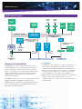
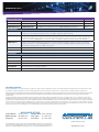
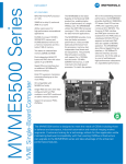
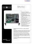
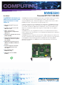
COMPUTING MVME5500 Data Sheet The MVME5500 is the flagship of our VME product line that enables higher levels of performance in a single VMEbus slot Freescale MPC7457 VME SBC The MVME5500 from Artesyn Embedded Technologies uses the MPC7457 processor running at 1 GHz, balanced with memory, dual independent local buses and I/O subsystems. The powerful Marvell system controller, with support for a 133 MHz host bus and a 133 MHz SDRAM memory bus, is well matched to the high speed processor. 512 KB of on-chip L2 cache and 2MB of L3 cache To match the system I/O to the outstanding processor performance, the MVME5500 provides dual 64-bit, 33/66 MHz PCI buses. Each PCI bus has a PMC site supporting cards running at 33 or 66 MHz. The Universe II VME interface and PMCspan connector are isolated from the PMC sites on a dedicated 33 MHz PCI bus segment so that both PMC sites are capable of 66 MHz operation. AltiVec coprocessor for high-performance computational applications The MVME5500 also offers a Gigabit Ethernet interface, a 10/100BaseTX Ethernet interface and two serial ports. All of this adds up to a set of well-balanced, high-performance subsystems for unparalleled performance. MPC7457 PowerPC® processor at 1GHz Two banks of soldered flash memory (32MB and 8MB) Dual independent 64-bit PCI buses and PMC sites with a bus speed of up to 66 MHz Gigabit Ethernet interface plus an additional 10/100BaseTX Ethernet interface 64-bit PCI expansion mezzanine connector allowing up to four more PMCs I/O compatibility with MVME51xx family Support for processor PMCs (PrPMCs) The MVME5500 series is designed to meet the needs of OEMs including those in defense and aerospace, industrial automation and transportation. Customers looking for a technology refresh for their application while maintaining backward compatibility with their existing VMEbus infrastructure can upgrade to the MVME5500 series and take advantage of the enhanced performance features. MVME5500 Data Sheet MVME5500 Block Diagram COM1 FP I/O L3 Cache 2MB Battery SDRRAM 133 MHz 512MB MPC7457 1GHz A32/D64-bit, 133 MHz Gigabit Ethernet Controller Ethernet 10/100BaseTX PHY COM2 Planar PCI Bridge & Memory Controller Discovery EIA232 EIA232 UART UART 66 MHz PCI Local Bus – A32/D64-bit PCI Bridge 66 MHz PCI Local Bus – A32/D64-bit Port 1 10/100/1000 BaseTX FP I/O NVRAM RTC Flash 32MB (soldered) 8MB (soldered) 33 MHz PCI Local Bus – A32/D64-bit PMC Slot 2 IPMC Slot 1 Universe II PMC FP I/O Port 2 10/100BaseTX FP I/O PMCspan Connector PMC FP I/O P2 Backwards Compatibility The MVME5500 continues the direction that Artesyn started with the MVME5100 series of providing a migration path from Artesyn’s embedded controllers and single-board computers (SBCs) to a single platform. This migration path enables OEMs to support varying I/O requirements with the same base platform, simplifying part number maintenance, technical expertise requirements and sparing. The MVME5500 series offers customers a migration path from the MVME2300, MVME2400, MVME2600, MVME2700 and MVME5100 boards to allow them to take advantage of features such as the MPC7455 processor, Gigabit Ethernet and dual independent 33/66 MHz PMC sites. P1 P2 I/O Modes The MVME5500 series supports two, jumper-configurable P2 I/O modes: PMC mode and IPMC mode. PMC mode is backward compatible with the MVME2300/ MVME2400 and MVME5100 in PMC mode. In PMC mode, 64 pins from PMC slot 1 and 46 pins from PMC slot 2 are available on P2 for PMC rear I/O. In IPMC mode, the MVME5500 series supports legacy MVME761 or MVME712M I/O modules (with limited PMC I/O) when an IPMC761 or IPMC712 PMC card is populated in PMC slot 1. In this configuration, PMC slot 2 contains some signals that are reserved for extended SCSI. MVME5500 Data Sheet Transition Modules The MVME761 transition module provides industry standard connector access to the IEEE 1284 parallel port, a 10BaseT or 100BaseT port via an RJ-45 connector, two DB-9 connectors providing access to the asynchronous serial ports configured as EIA-574 DTE and two HD-26 connectors providing access to the sync/async serial ports. These serial ports, labeled as Serial 3 and Serial 4 on the faceplate of the MVME761, are individually user-configurable as EIA-232, DCE or DTE via the installation of Artesyn Serial Interface Modules (SIMs). A P2 adapter board provides interface signals to the MVME761 transition module. Two separate P2 adapter boards are available: one for 3-row backplanes and one for 5-row backplanes. The 3-row P2 adapter board provides connection for 8-bit SCSI. A 5-row P2 adapter board supports 16-bit SCSI and PMC I/O. The MVME712M transition module provides industry standard connector access to the Centronics parallel port, a narrow SCSI port, and four DB-25 connectors providing access to the asynchronous/synchronous serial ports jumper configurable as EIA-232 DCE or DTE. A P2 adapter board provides interface signals to the MVME712M transition module. The 3-row P2 adapter board also provides connection for 8-bit SCSI. To gain access to the additional user-definable I/O pins provided via the 5-row VME64 extension connector, a special P2 adapter board is available. This adapter panel replaces the traditional 3-row P2 adapter board and extends its capability by providing access to the PMC I/O pins. Software Support Firmware Monitor Firmware must fulfill the traditional functions of power-on self-test (POST), initialization, low-level setup and debug, and operating system booting. Artesyn’s innovative firmware (known as MOTLoad) that is resident on the MVME5500 exceeds these requirements with expanded features such as interrupt driven I/O, more comprehensive power-up tests and extensive diagnostics with new scripting capability. And of course, MOTLoad provides a debugger interface similar to the time proven “bug” interface on previous VMEbus boards from Artesyn. Operating Systems and Kernels WindRiver Systems and VxWorks are available for the MVME5500. Libraries VSI/Pro VSIPL libraries from MPI Software Technology are available on the MVME5500. BETA 4.0 NDDS from Real Time Innovations (RTI) running over GbE and Native VME are available on the MVME5500 through RTI. Specifications Processor Microprocessor: MPC7457 Clock Frequency: 1GHz On-chip L1 Cache (I/D): 32 KB/32 KB On-chip L2 Cache (I/D): 512 KB L3 Cache: 2MB System Controller Marvell GT-64260B Main Memory Type: PC133 ECC SDRAM Speed: 133 MHz Configurations: 512 MB in two banks Flash Memory Type: EEPROM, on-board programmable Capacity: 40MB total in two banks of 32MB and 8MB, both soldered Write Protection: 32MB of surface-mount flash is write protectable via jumper NVRAM Capacity: 32 KB (4 KB available for users) Cell Storage Life: 50 years at 55 °C Cell Capacity Life: Five years at 100% duty cycle, 25 °C Removable Battery: Yes Counters/Timers TOD Clock Device: M48T37V Real-Time Timers/Counters: Eight, 32-bit programmable Watchdog Timer: Time-out generates reset MVME5500 Data Sheet VMEbus Interface: ANSI/VITA 1-1994 VME64 (IEEE STD 1014) Controller: Tundra Universe II DTB Master: A16-A32; D08-D64, SCT, BLT DTB Slave: A24-A32; D08-D64, BLT, UAT Arbiter: RR/PRI Interrupt Handler/Generator: IRQ 1-7/Any one of seven IRQs System Controller: Yes, jumperable or auto detect Location Monitor: Two, LMA32 Ethernet Interfaces Port 1 Intel® 82545GM Gigabit Ethernet controller. PCI Expansion Connector Address/Data: A32/D32/D64 PCI Bus Clock: 33 MHz Signaling: 5 V Power: +3.3 V, +5 V, ±12 V Connector: 114-pin connector located on MVME5500 planar, same location as on MVME5100 planar Power Requirements MVME5500-0163: MVME5500-0163 with IPMC712/761: Note: In a 3-row chassis, PMC current should be limited to 19.8 watts (total of both PMC slots). In a 5-row chassis, PMC current should be limited to 46.2 watts (total of both PMC slots). • Controller: • Interface Speed: 10/100/1000 Mbps Board Size • Connector: Routed to front panel RJ-45 Height: 233.4 mm (9.2 in.) Port 2 • Controller: Controller integrated into GT-64260B system controller • Interface Speed: 10/100 Mbps • Connector: Routed to front panel RJ-45 or optionally routed to P2, RJ-45 on MVME761 +5V ±5% 6.7 A typ., 8.0 A max. 7.6 A typ., 9.2 A max. Depth: 160.0 mm (6.3 in.) Front Panel Height: 261.8 mm (10.3 in.) Width: 19.8 mm (0.8 in.) Max. Component Height: 14.8 mm (0.58 in.) Asynchronous Serial Ports IPMC Modules Controller: Two TL16C550C UARTs PMC Interface Number of Ports: Two, 16550 compatible Address/Data: A32/D32/D64, PMC PN1, PN2, PN3, PN4 connectors Async Baud Rate, bps max.: 38.4 K EIA-232, 115 Kbps raw Connector: Routed to front panel RJ-45; one on planar for development use Dual IEEE P1386.1 PCI Mezzanine Card Slots PCI Bus Clock: 33 MHz Signaling: 5 V Module Type: Basic single-wide; P2 I/O Address/Data: A32/D32/D64, PMC PN1, PN2, PN3, PN4 connectors SCSI Bus PCI Bus Clock: 33/66 MHz PCI Local Bus DMA: Yes, with PCI local bus burst Signaling: 3.3 V or 5 V, configurable with keying pin Asynchronous (8-bit mode): 5.0MB/s Power: +3.3 V, +5 V, ±12 V Ultra SCSI: 20.0MB/s (8-bit mode), 40.0MB/s (16-bit mode) Module Types: Two single-wide or one doublewide, front panel or P2 I/O, PMC and PrPMC support Note: 16-bit SCSI operation precludes the use of some PMC slot 2 signals Controller: Symbios 53C895A MVME5500 Data Sheet Synchronous Serial Ports Parallel Port Controller: 85230/8536 Controller: PC97307 Number of Ports: Two (IPMC761); one (IPMC712) Configuration: 8-bit bi-directional, full IEEE 1284 support; Centronics compatible (minus EPP and ECP on MVME712M) Configuration: IPMC761: TTL to P2 (both ports), SIM configurable on MVME761; IPMC712: EIA-232 to P2 Baud Rate, bps max.: 2.5M sync, 38.4 K async Oscillator Clock Rate (PCLK): 10 MHz/5 MHz Asynchronous Serial Ports Modes: Master only Power Requirements (Additional power load placed on MVME5500 with IPMC installed) +5 V: +3.3 V: Controller: 16C550 UART; 85230/8536 IPMC761 0.5 A max. 0.75 A max. IPMC712 0.5 A max. 0.75 A max. Number of Ports: Two (IPMC761); three (IPMC712) Configuration: EIA-574 DTE (IPMC761); EIA-232 (IPMC712) Async Baud Rate, bps max.: 38.4 K EIA-232, 115 Kbps raw Transition Modules I/O Connectors MVME761 MVME712M Asynchronous Serial Ports: Two, DB-9 labeled as COM1 and COM2 Three, DB-25 labeled Serial 1, Serial 2 and Serial 3 Synchronous Serial Ports: Two, HD-26 labeled as Serial 3 and Serial 4 (user-configurable via installation of SIMs); two 60-pin connectors on MVME761 planar for installation of two SIMs One, DB-25 labeled as Serial 4 Parallel Port: HD-36, Centronics compatible D-36, Centronics compatible Ethernet: 10BaseT or 100BaseT, RJ-45 Not available SCSI: 8- or 16-bit, 50- or 68-pin connector via P2 adapter 8-bit, standard SCSI D-50 Board Size Height: 233.4 mm (9.2 in.) Depth: 80.0 mm (3.1 in.) Front Panel Height: 261.8 mm (10.3 in.) Front Panel Width – MVME761: 19.8 mm (0.8 in.) Front Panel Width – MVME712M: 39.6 mm (1.6 in.) All Modules DEMONSTRATED MTBF Based on field analysis, estimated MTBF is 610,000 hours. Environmental Temperature: Humidity (NC): Vibration: Operating Non-operating Electrom agnetic Compatibility (EMC) 0 °C to +55 °C (inlet air temp. with forced air cooling*) –40 °C to +85 °C Intended for use in systems meeting the following regulations: 5% to 90% 5% to 90% 1 G sinusoidal, 5 – 100 Hz 2 axes horizontal and vertical (NEBS1) * Reference cooling requirements section of the user’s manual. Note: Conformal coating these products may result in up to a 2 °C reduction in operating temperature limits. • U.S.: FCC Part 15, Subpart B, Class A (non-residential) • Canada: ICES-003, Class A (non-residential) Artesyn board products are tested in a representative system to the following standards: • CE Mark per European EMC Directive 89/336/EEC with Amendments; Emissions: EN55022 Class A; Immunity: EN55024 Safety All printed wiring boards (PWBs) are manufactured with a flammability rating of 94V-0 by UL recognized manufacturers MVME5500 Data Sheet Ordering Information New Part Number Replaces Description Weight MVME55006E-0161R MVME55006E-0161 1GHz MPC7457 PowerPC processor, 512MB SDRAM, Scanbe handles 6E 0.40 kg MVME55006E-0163R MVME55006E-0163 1GHz MPC7457 PowerPC processor, 512MB SDRAM, IEEE handles 6E 0.43 kg Related Products MVME712M6E Transition module with one DB-25 sync/async serial port, three DB-25 async serial port, one AUI connector, one D-36 parallel port, and one 50-pin 8-bit SCSI; includes 3-row DIN P2 adapter board and cable 5E MVME7616E-001 Multifunction rear I/O PMC module; 8-bit SCSI, one parallel port, two async and two sync/ async serial ports. Transition module with two DB-9 async serial port connectors, two HD-26 sync/async serial port connectors, one HD-36 parallel port connector, one RJ-45 10/100 Ethernet connector; includes 3-row DIN P2 adapter board and cable (for 8-bit SCSI) 5E MVME7616E-011 Transition module with two DB-9 async serial port connectors, two HD-26 sync/async serial port connectors, one HD-36 parallel port connector, one RJ-45 10/100 Ethernet connector; includes 5-row DIN P2 adapter board and cable (for 16-bit SCSI); requires backplane with 5-row DIN connectors 5E PMCSPAN16E-002 Primary PMCSPAN-002 with original VME Scanbe ejector handles 5E PMCSPAN16E-010 Secondary PMCSPAN-010 with original VME Scanbe ejector handles 5E Documentation V5500A/IH MVME5500 Single-Board Computer Installation and Use V5500A/PG MVME5500 Single-Board Computer Programmer’s Reference Guide VME761A/IH MVME761 Transition Module Installation and Use VME712MA/IH MVME712M Transition Module Installation and Use MOTLODA/UM MOTLoad Firmware Package User’s Manual PMCSPANA/IH PMCspan PMC Adapter Carrier Board Installation and Use Solution Services Artesyn Embedded Technologies provides a portfolio of solution services optimized to meet your needs throughout the product lifecycle. Design services help speed time-to-market. Deployment services include global 24x7 technical support. Renewal services enable product longevity and technology refresh. PICMG, AdvancedTCA, ATCA and the AdvancedTCA logo are trademarks of PICMG. Service Availability is a proprietary trademark used under license. Intel and Xeon are trademarks of Intel Corporation or its subsidiaries in the Unites States and other countries. Microsoft and Windows are registered trademarks of Microsoft Corporation. All other product or service names are the property of their respective owners. This document identifies products, their specifications, and their characteristics, which may be suitable for certain applications. It does not constitute an offer to sell or a commitment of present or future availability, and should not be relied upon to state the terms and conditions, including warranties and disclaimers thereof, on which Artesyn Embedded Technologies may sell products. A prospective buyer should exercise its own independent judgment to confirm the suitability of the products for particular applications. Artesyn reserves the right to make changes, without notice, to any products or information herein which will, in its sole discretion, improve reliability, function, or design. Artesyn does not assume any liability arising out of the application or use of any product or circuit described herein; neither does it convey any license under its patent or other intellectual property rights or under others. This disclaimer extends to any prospective buyer, and it includes Artesyn’s licensee, licensee’s transferees, and licensee’s customers and users. Availability of some of the products and services described herein may be restricted in some locations. WORLDWIDE OFFICES Tempe, AZ U.S.A. +1 888 412 7832 Munich, Germany +49 89 9608 2552 Hong Kong +852 2176 3540 Shanghai, China +86 21 3395 0289 Tokyo, Japan +81 3 5403 2730 Seoul, Korea +82 2 3483 1500 www.artesyn.com Artesyn Embedded Technologies, Artesyn and the Artesyn Embedded Technologies logo are trademarks and service marks of Artesyn Embedded Technologies, Inc. All other names and logos referred to are trade names, trademarks, or registered trademarks of their respective owners. © 2014 Artesyn Embedded Technologies, Inc. MVME5500-D1 05/30/14