1
∗
Towards formal testing of jet engine Rolls-Royce BR725
Greg Holland1 , Temesghen Kahsai2 ,
Markus Roggenbach2 , Bernd-Holger Schlingloff3
1
2
3
Rolls-Royce Plc. Derby, UK.
Department of Computer Science, Swansea University, UK.
Humboldt University Berlin, Fraunhofer FIRST, Germany.
Abstract. The Rolls-Royce B R 725 is a newly designed jet engine for ultra-longrange and high-speed business jets. In this paper we apply our theory of formal
testing [5,6] to the starting system of the Rolls-Royce B R 725 control software.
To this end we model the system in C SP, evaluate test suites against the formal
model, and finally execute test suites in an in-the-loop setting of the SUT. This
case study demonstrates the applicability of our testing approach to industrial
systems: it scales up to real world applications and it potentially fits into current
verification and quality assurance processes, as e.g., in place at Rolls-Royce.
1
Introduction
Jet engines belong to the safety critical systems of an air plane. Their control software
can be classified as a reactive system: it accepts commands from the pilot, receives
status messages from the airframe and the engine sensors, and issues commands to
the engine. Here, we report on the successful application of our theory of specification
based testing [5,6] to such systems.
Our testing theory has been developed for the formal specification language C SPC ASL [10]. C SP-C ASL allows to formalize systems in a combined algebraic / process
algebraic notation. To this end it integrates the process algebra C SP [3,11] and the algebraic specification language C ASL [8]. In the context of this paper we restrict C SPC ASL to (a sub-language of) C SP M, the machine-readable version of C SP.
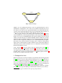
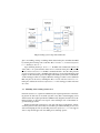
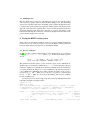
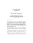
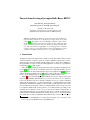
Figure 1 shows our testing approach in a nutshell. Specification, Implementation and
Test Cases are mutually related artifacts. Specifications and Test Cases are written in
C SP-C ASL, the Implementation is treated as a black box. Test cases can be constructed
either from the specification – as shown in the triangle – or independently from it. The
specification determines the alphabet of the test suite, and the expected result of each
test case. The expected result is coded in a colouring scheme of test cases. If a test case
is constructed which checks for the presence of a required feature (according to the
specification), we define its colour to be green. If a test case checks for the absence of
some unwanted behaviour, we say that it has the colour red. If the specification does
neither require nor disallow the behaviour tested by the test case, i.e., if a System Under
Test (SUT) may or may not implement this behaviour, the colour of the test case is
∗
We would like to thank Rolls-Royce for supporting the internship of the second author. This
work was supported by EPSRC under the grant EP/D037212/1.
determines
colour of
Specification
Test Cases
is
ar
ee
xe
cu
de
ted
t
ve erm
on
rd in
ict es
of
are constructed
with respect to
to
ed
m
fin
fro
re
ed
riv
de
is
Implementation
Fig. 1. Validation triangle
defined to be yellow. During the execution of a test on a particular SUT, the verdict is
determined by comparing the colour of the test case with the actual behaviour. A test
fails, if the colour of the test case is green but the SUT does not exhibit this behaviour,
or if the colour is red but the behaviour can be observed in the SUT. The execution of a
yellow test case yields an inconclusive verdict. Otherwise, the test passes.
Here, we apply our theory to the starting system of Rolls-Royce B R 725 4 software
control. The B R 725 is a newly designed jet engine for ultra-long-range and high-speed
business jets. It is part of the B R 700 family. We model the starting system in C SP and
validate our model using the C SP simulator P RO B E. We then evaluate the test suites
against the formal model. Such evaluation is done using the model checker F DR 2. Part
of the test suites is inspired by existing test cases of the B R 700 family jet engines.
We execute our test suite in an in-the-loop setting on the so-called “rig”. This puts the
engine control system through test scenarios identical to those carried out in engine test
stand testing, however with considerable lower cost, reduced risk, and less burden on
human and mechanical resources.
Outline In Section 2 we give an overview of the test evaluation theory from [5] and a
brief introduction to C SP M and F DR 2. In Section 3 we describe a control system of
a jet engine in general and the starting system of the Rolls-Royce B R 725 jet engine in
particular. We also show how we model the latter in C SP M. Subsequently, in Section 4
we show how we evaluate and execute test cases.
2
Testing in C SP-C ASL
In this section we give an overview of the theory of specification-based testing presented
in [5,6]. The theory is based on the specification language C SP-C ASL [10] which allows
to formalize computational system in a combined algebraic / process algebraic notation.
C SP-C ASL uses the process algebra C SP [3,11] for the modeling of reactive behaviour,
whereas the communicated data is specified in C ASL [8]. C SP-C ASL has been deployed
in the modeling [2] and verification [4] of an electronic payment system.
In [5], a theory for the evaluation of test cases with respect to C SP-C ASL specifications has been developed. In summary, the main benefits of this theory are as follows.
4
In the rest of the paper we will refer to this engine type simply as B R 725.
– Separation of test case construction from specification and implementation: A test
case only refers to the signature of a specification. This allows to start the development of test suites as soon as an initial, abstract version of the specification is
available, in parallel to the development of the actual implementation.
– Separation of the test oracle and the test evaluation problem: Test cases are constructed with respect to an (abstract) specification and executed on a (concrete)
implementation. The specification determines the expected result of a test case, and
the implementation the verdict. Therefore, the intrinsically hard test oracle problem can be solved before the actual execution, whereas test evaluation can be done
online.
– Positive and negative test cases: The intention of a test case with respect to a specification is coded by a colouring scheme. It is possible to construct test cases for the
intended behaviour (colour green) as well as for unwanted behaviour (colour red)
of an implementation.
– Three-valued evaluation scheme for test cases: The colour of a test case as determined by a specification is either green, red or yellow; the test verdict is either pass,
fail or inconclusive. The test verdict is obtained by comparing intended and actual
behaviour of an SUT. Yellow test cases lead to inconclusive test verdicts, indicating
that the specification is not complete in this point.
A specification with monomorphic data and no internal non-determinism in the process has resolved all design decisions. We show in [5] that such specifications have no
yellow test cases.
A test case is executed on a particular SUT. In [5] we define a point of control and
observation (PCO) in order to map the events of the SUT to the event names (concrete:
C ASL-terms) of the test case. A PCO P = (A, k...k, D) of an SUT consists of the
alphabet A of events of the SUT, a mapping k...k : A −→ TΣ (X) which returns a term
for each a ∈ A, and a direction D : A −→ {ts2sut, sut2ts}. ts2sut stands for signals
which are sent from the testing system to the SUT, and sut2ts stands for signals which
are sent in the other direction.
We also define the execution of a test case on an SUT at a PCO. The test verdict is
obtained algorithmically by comparing the actual behaviour of the SUT a with the trace
of the test case. The noncompliance to a green test case or compliance to a red one leads
to test failure. The compliance to a green test case or noncompliance to a red one leads
to passing the test.
2.1
C SP M and F DR 2
C SP M [11,12] is the machine readable version of C SP, which also includes a simple
functional programming language. Data in C SP M is monomorphic.
We choose C SP M instead of C SP-C ASL thanks to the nature of the system specifications we formalize. These specifications do not require loosely specified data or
complex data structures. Instead, they use simple data types only; mostly they speak
about booleans and finite subranges of numbers. These data types are available in the
type system of C SP M, and they can also be modelled within C ASL. This justifies the
use of C SP M instead of C SP-C ASL.
Employing C SP M allows us to use the model checker F DR 2 [7,11] to prove the
test colouring in an automatic way. When using full C SP-C ASL, the proof of colouring has to be done using the C SP-C ASL-P ROVER [9], which as an interactive theorem
prover requires costly human interaction. F DR 2 is a model checking tool developed by
Formal Systems (Europe). The input language of F DR 2 is C SP M. F DR 2 offers, e.g.,
to check for trace refinement, or to check if a process is deterministic. The following
table collects the syntax of some C SP process constructs that we will be using in order
to model the B R 725 Starting System; for a complete description of C SP M see [11].
C SP M- Process definition
P /\ Q
-- Interrupt
P [> Q
-- Untimed timed out
P [b || a] Q
-- Alphabetized parallel
P ||| Q
-- Interleaving
P [] Q
-- External choice
P [[a<-b]]
-- Renaming
P \ a
-- Hiding
3
Modelling the BR725 starting system in C SP
In this section we give a brief description of the control system of the jet engine in general, and the starting system functionality in particular. We also report how the modeling
of the starting system in C SP has been carried out. We work on the same level of abstraction as the Rolls-Royce system verification team which tests the engine control
system on system level.
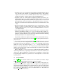
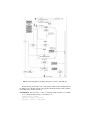
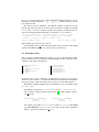
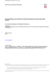
The main component of the control system of a jet engine is the Electronic Engine
Controller (EEC). A simplified view of the B R 725 EEC architecture and its interfaces
with the engine is shown in Figure 3. The EEC encapsulates all signalling aspects of the
engine; it controls, protects, and monitors the engine. In order to provide fault-tolerance,
the EEC is realised as a dual-channel system. Its control loop involves: reading data
from sensors and other computer systems in the aircraft, receiving commands from the
pilot, calculating new positions of the engine actuators, and issuing commands to the
engine actuators. In its monitoring function it transmits data about the engine condition
and information on any failures diagnosed on the electronics back to the aircraft. Here
we focus on the Starting System, one of the many functionalities the EEC provides.
3.1
Starting System of B R 725
The jet engine B R 725 can be started in both, on-ground and in-flight situations. Furthermore, the pilot can select between Automatic or Manual starting mode. Moreover,
the Starting System may be used to provide engine Cranking.
The detected situation (on-ground or in-flight) together with the selected starting
mode (automatic or manual) results in four different control flows in which the EEC
controls the engine. Cranking adds two further flows of the EEC, namely dry and wet
cranking (i.e., without and with fuel on respectively). In the following we discuss the
manual on-ground starting sequence. Starting the jet engine essentially involves three
steps:
Fig. 2. Electronic Engine Controller Architecture – Courtesy of Rolls-Royce
1. A motor – the so-called Starter – which is mechanically coupled to a shaft of the
engine, starts to rotate the engine.
2. When the shaft has reached a sufficient rotational speed, fuel is allowed to flow to
the combustion chamber and the engine lights up.
3. When the rotational speed of the engine reaches a threshold the engine start is
complete.
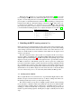
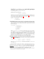
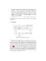
Figure 3 shows an abstraction of the basic system architecture of a Rolls-Royce jet
engine starting system. The main signals transmitted between the components are as
follows. In the Cockpit the pilot has a start switch in order to initiate the starting sequence; the pilot also has a fuel switch. The Airframe informs the EEC if the plane is
in-flight or on-ground. The EEC can switch the Starter On and Off, can Open and Close
the fuel SOV (Shut-Off Valve), and can turn the Ignition On and Off. The engine reports
back to the EEC information about the shaft speed and the TGT (Turbine Gas Temperature). For B R 725 the Rolls-Royce Starting Subsystem Definition Document (SSDD)
makes the Starting System within the EEC specific to this engine. This document describes all aspects of the Starting System: it gives an overview of the Starting System
in general, it presents so-called activity diagrams and explains them in plain English.
In the following we give an example of such an activity diagram and its accompanying
text.
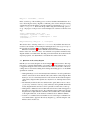
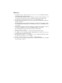
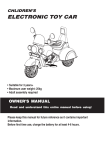
Figure 4 shows the internal logic of the manual ground start in the form of an activity
diagram. These activity diagrams are formulated in an informal, graphical specification
language. This language was specifically developed by Rolls-Royce in order to describe
engine controllers. An example of an accompanying text would be the following:
I3005/1 When NH reaches the required speed, the pilot switches the Fuel Control
Switch to RUN.
Note that every specification line is identified with a unique number, in our example
with I3005/1. Rolls-Royce makes use of this during the testing process as a coverage
criterion: it is required that there is at least one test case for every line in the specification. Figure 4 shows the Manual Ground Start (MGS) functionality which allows the
pilot to start the engine manually. The flow from the start point to the second transition
shows that the MGS can only be initiated when the aircraft is on the ground and the en-
Fig. 3. Starting system component architecture
gine is not running, starting or cranking. In this situation the pilot can initiate the MGS
by selecting the following control switches: Master Crank to On, Continuous Ignitions
to On, and Engine Start to On.
Upon switching the Engine Start to On, the EEC will command the Starter Air
Valve (SAV) to be opened and the starter motor is activated. If the pilot now switches
the Fuel Control Switch to Run the EEC commands the fuel to flow. If at this point the
Continuous Ignitions is still On the EEC ignites the motor (not shown in the Figure) and
begins to monitor the shaft speed of the engine. Should this speed reach a certain threshold the starting procedure is complete. While the starting procedure is active within the
EEC, the pilot can abort it by switching the Master Crank or the Fuel Control to Off.
If the pilot switches the Continuous Ignitions to Off the starting procedure ends in an
error state.
3.2
Modelling of the starting system in C SP
Our main objective is to capture in a faithful way the original specification of the Starting System. To this end, we model the system in a way that a natural mapping can be
drawn between the original specification (SSDD activity diagrams) and the C SP model.
In the following we describe some aspects of the modeling in C SP of the manual onground starting procedure.
We have modeled the system in a two step approach: first we formalize the ’normal’
execution pattern of the system. Only in a second step we add the handling of error cases
such as interrupting the start by switching Continuous Ignitions to Off. C SP supports
such a compositional approach of modelling via its interrupt operator.
Fig. 4. Activity diagram for manual ground start - Courtesy of Rolls-Royce
In the following we describe some of the patterns which we have identified in the
modeling process. We first describe some patterns and discuss then how their combination results in the overall control-flow.
Switch Buttons have two states: ON and OFF. Pressing a button in state OFF will turn
it ON, releasing a button in state ON will turn it OFF.
channel press, release
ButtonOFF = press -> ButtonON
ButtonON = release -> ButtonOFF
We instantiate ButtonON and ButtonOFF to form the different switch buttons
available in the Cockpit for the Starting System. This is done by simply using the
C SP renaming operator, e.g., for MasterCrank:
channel mc_press, mc_release
MasterCrank = ButtonOFF[press <- mc_press
release <- mc_release]
All button processes run in an interleaved way. This corresponds to arbitrary press /
release operations in the Cockpit. Note how this specification5 covers in an obvious
way part of the activity diagram in Figure 4.
Buttons =
MasterCrank
||| MasterStart
||| EngineStartON
Active waiting The starting sequence can only proceed when the following events happens: (1) the checks for Aircraft and Engine condition has been successful, (2) the
pilot has issued the necessary starting commands. This is captured in the C SP model
in the following way:
InteractEEC= (CheckConditions
[|{synchStart}|]
CrankAndIgnite)
\ {synchStart}
; FuelAndSAV
; MasterIdle
where CheckConditions is the process that checks for the Aircraft and Engine condition. CrankAndIgnite is the process that handles the input of the
pilot; namely the cranking and the ignition commands. CheckConditions and
CrankAndIgnite synchronize on the synchStart event, only when the synchronization is successful the process FuelandSAV takes over. The FuelandSAV
and MasterIdle processes capture the rest of the starting sequence.
Interleaving of decisions At different points of the activity diagram there are decisions
that happen in an interleaved way. We model this scenario using the external choice
operator6 in the following way:
CrankAndIgnite =
[]
mc_press -> ci_press -> InitStartOK
ci_press -> mc_press -> InitStartOK
Here, the process CrankAndIgnite offers the to first switch MasterCrank or
ContIgnition.
The whole manual on-ground start sequence is represented by the process MGS.
The processes InteractEEC and Buttons runs in an alphabetized parallel. This
corresponds to the interaction of the pilot (trough the Cockpit switches) and the EEC.
5
6
We leave out the code of the EngineStartON which as a push button has no state.
In order to have state names available, we choose the semantically equivalent encoding of
interleaving in terms of external choice and action prefix.
MGS_Core = InteractEEC || Buttons
In the second step of the modeling process we have identified and handled the error
cases. Observing the activity diagrams, at different points of time during the starting
sequence the pilot has the ability to abort the sequence by releasing the FuelControl
or the ContIgnition. We model this procedure using the C SP interrupt operator P ∧ Q – the progress of the process P can be interrupted on occurrence of the first event
of Q.
channel commandIgnOFF, abort, error
InterruptFC = fc_release -> abort -> SKIP
InterruptCI = ci_release -> commandIgnOFF ->
(InteractEEC /\
MGS_ErrorHandling = MGS_Core
/\
Error
InterruptFC
The abortion due to releasing of the MasterCrank is only available after the Command Fuel ON event has occurred and prior reaching the Starter Disengagement Speed.
In a pictorial way in Figure 4, this is identified by the dotted box.
Simulations with the C SP animator P RO B E, discussions with the Rolls-Royce verification team, and – last but not least – the structural correspondence with the activity
diagram validate our formal model. Checking our model in F DR 2 shows that it has the
expected properties: it is deterministic, it is deadlock-free and it is livelock-free.
3.3
Questions on the activity diagram
Rolls-Royce uses activity diagrams as shown in Figure 4 merely as memos. The engineers share a common understanding of jet engines, the activity diagrams serve more
to trigger knowledge how the control software works. Here, we list some of the shortcomings that we encountered during the modeling and reading process of the SSDD
specification document.
– Although the Engine Start is a momentary button and Master Crank is a push button
with two states both are shown with the same symbol in the activity diagram. That
the Engine Start is a momentary button becomes clear from the textual description
of the activity diagram. This explains also why there is no interrupt related to this
button.
– We identically modeled both boxes which monitor speed (Monitor Starter Disengagement Speed, Monitor Achieving of Idle) relatively to the signal NH, while in the
activity diagram the first box has no self-loop and the second box has a self-loop.
– Although the commands Command IGN ON and Command IGN OFF appear at
first sight to be related, they are not: the command Command IGN ON is given by
the pilot in the cockpit while the command Command IGN OFF is sent by the EEC
to the engine. Therefore, we model these commands via two different channels.
– As there is a command Command FUEL ON one would expect command Command FUEL OFF to appear in the activity diagram, e.g., when aborting the start.
However, this is not the case.
3.4
Modeling in C SP
Here we outline the pros and cons of modeling the system in C SP. On the positive
side, various C SP operator came very handy in the modeling process. The interleaving
operator, the sequential composition, the hiding operator and the interrupt allowed us
to capture many system aspects in an elegant way. On the negative side, the global state
approach of C SP forced us to explicitly have one process name per transition (arrow in
the activity diagrams). This allowed us to take care of or ignore state changes of the
buttons while following the control flow of the activity diagram. Overall, however, C SP
served well in modeling such a controller.
4
Testing the BR725 starting system
In this section we describe the evaluation of test cases, how we establish the PCO and
execute the test cases on the rig. Some test cases for the B R 725 manual ground start
have been inspired from previous projects concerning the B R 700.
4.1
Test case evaluation
In [5] we present a syntactic characterization of the semantical notion of colouring a
test case T = t1 → t2 → . . . → tn → STOP, n ≥ 0. To this end we define a process
CheckT :
CheckT
= ((P k T)[[R1 ]] . . . [[Rn ]] |[ obs ]| count(n)) \ {obs}
count(n : Nat) = if n = 0 then OK → SKIP else count(k − 1)
The synchronous parallel operator k forces P and T to agree on all communications.
Should P agree to execute the communications t1 , . . . , tn of T in exactly this order, this
results in a sequence of n communications. All these communications are renamed into
obs via the predicates Ri . The process count communicates OK after the execution of
n obs0 s. Hiding the communication obs makes only this OK visible. A test process is
red, iff CheckT 6=T OK → SKIP. For a test process to be green, it is necessary that
CheckT =T OK → SKIP. As our model is deterministic, this necessary condition
becomes a sufficient one.
As a first test cases we encode a supposedly successful on-ground manual start. The
following is the input test script for F DR 2:
channel OK, obs
GREEN = OK -> SKIP
TC1 = aircraftCondition.true -> engineCondition.true -> mcpress -> ci_press
-> engineStartON -> sav.open -> fc_press -> commandFuelON -> commandIgnON
-> readNH.17 -> sav.close -> readNH.68 -> started -> STOP
CheckT = (
( ( MGS [ {|aircraftCondition.true,...,started|}
|] TC1
) [[aircraftCondition.true <- obs,...,started <-obs]]
) [| {obs} |] obs -> ... -> obs -> OK -> STOP
) \ { obs }
assert CheckT [T= GREEN
assert GREEN [T= CheckT
% Parallel
% Renaming
% Parallel
%
Hiding
% Verify the colour
In CheckT we encode the traces condition. Equality checking in F DR 2 is done by
checking for mutual refinement, i.e., vT ∧ wT ⇒ =T . F DR 2 instantly proves that
both asserations hold.
For red test cases it is sufficient to show that the condition on the traces doesn’t
hold. To this end we check if one of the assertions for the traces condition concerning
CheckT fails. T2 encodes a manual on-ground start sequence, in which the first NH
value is less than the prescribed threshold (15). Therefore, T2 is colored red.
TC2 = aircraftCondition.true -> engineCondition.true -> mc_press -> ci_press
-> engineStartON -> sav.open -> fc_press -> commandFuelON -> commandIgnON
-> readNH.10 -> sav.close -> readNH.68 -> started -> STOP
assert not GREEN [T= CheckT
assert not CheckT [T= GREEN
F DR 2 instantly proves the test case to be red.
As the datatypes in C SP M are all monomorphic, and as our model of the starting
system is deterministic, there are no yellow test cases (see Section 2).
4.2
Establishing a PCO
The test verdict is obtained during the execution of a test case in the hardware-in-theloop rig. Rolls-Royce uses a proprietary scripting language in order to write test scripts;
a snippet of such script is shown below:
1
2
3
4
5
6
Set("MasterCrankCnd",1)
WaitTime(2)
Set("REngContinuousIGN",1)
WaitTime(2)
Set("REngStartCnd",1)
WaitTime(2)
7
8
9
10
11
12
13
Set("REngStartCnd",0)
WaitUntil("NHP>15")
Set("MasterLever",0)
WaitUntil("LIT==1")
Set("FlightStatus",1)
WaitUntil("NHP>65",60)
...
For instance, line 1,3,5 are commands to switch the Master Crank, Continuos Ignition
and Fuel Control switch to ON respectively. The time delay inbetween commands is
necessary in order to capture the signal, and store it in a log for an offline analysis.
We link this scripting language and our formulation of tests by defining a PCO
P = (A, k...k, D):
– The alphabet of the SUT is A = { MasterCrankCnd, . . . ,FlightStatus}.
– We use ASN.1 (Abstract Syntax Notation One) [1] to map primitive events to
C SP M events.
MasterCrankCnd ::= ENUMERATED {
mc_press
(1)
mc_release
(0) }
MasterLever ::= ENUMERATED {
fc_press
(1)
fc_release
(0) }
For example, we describe MasterCrankCnd and MasterLever as the ASN.1
type ENUMERATED; MasterCrankCnd can take only the values specified in
the list, e.g. the value 0 stands for mc press.
– The direction of primitive events are defined as follows: ts2RIG stands for signals which are sent from the testing software to the rig. For instance, all commands set(...) in the test script above are of type ts2RIG. The other direction
RIG2ts, which stands for signals which are sent from the rig to the testing software. Those are captured by different logging systems; for instance, the command
Log HST(...) logs primary variables of the EEC, Log Mod(...) logs simulation parameters and Log HST(...) logs aircraft discretes. The following are
examples of such logging system:
Log_HST("mstrstrtswtchsncckpt")
Log_Mod("P30")
;Master Start Switch - EEC variable
;Engine pressure simulation parameters
After running the test case on the rig, the test verdict is obtained “offline” by analyzing
the different logs.
5
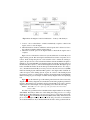
Conclusions
Fig. 5. Overall modelling and testing process
In this paper we have applied the theory of formal testing based on C SP-C ASL,
to the starting system of Rolls-Royce B R 725 control software. We have modeled the
system in C SP, evaluate test suites against the formal model using the model checker
F DR 2. We executed the test suites in an in-the-loop setting of the SUT. The SUT did
not show any deviation from the intended behaviour, i.e., the testing process increased
the trust in its correctness. The overall approach described in this paper is reported
in Figure 5. This case study demonstrates the applicability of our testing approach to
industrial systems: it scales up to real world applications and it potentially fits into
current verification practice at Rolls-Royce. Future work will address the questions of
(automatic) test case generation and of suitable test coverage criteria. Furthermore, we
will improve our theory of testing for enhancement in order to formally accommodate
modeling in which error handling is added later on.
References
1. O. Dubuisson. ASN.1 communication between heterogeneous systems. ISBN 0-12-63333610. Morgan Kaufmann, September 2000.
2. A. Gimblett, M. Roggenbach, and H. Schlingloff. Towards a formal specification of an
electronic payment systems in C SP-C ASL. In WADT’04, LNCS 3423. Springer, 2005.
3. C. A. R. Hoare. Communicating Sequential Processes. Prentice Hall, 1985.
4. T. Kahsai and M. Roggenbach. Property preserving refinement for CSP-CASL. In WADT’08.
Springer, To appear.
5. T. Kahsai, M. Roggenbach, and B.-H. Schlingloff. Specification-based testing for refinement. In M. Hinchey and T. Margaria, editors, SEFM 2007, pages 237–246. IEEE Computer
Society, 2007.
6. T. Kahsai, M. Roggenbach, and B.-H. Schlingloff. Specification-based testing for software
product lines. In SEFM 2008, pages 149–158. IEEE Computer Society, 2008.
7. F. S. E. LTD. Failures-divergence refinement: Fdr2 user manual, 2005.
http://www.fsel.com/.
8. P. D. Mosses, editor. CASL Reference Manual. LNCS 2960. Springer, 2004.
9. L. O’Reilly, Y. Isobe, and M. Roggenbach. CSP-CASL-Prover: a generic tool for process
and data refinement. In AVOCS 2008, 2008.
10. M. Roggenbach. CSP-C ASL – A new integration of process algebra and algebraic specification. Theoretical Computer Science, 354, 2006.
11. A. Roscoe. The theory and practice of concurrency. Prentice Hall, 1998.
12. B. Scattergood. The Semantics and Implementation of Machine-Readable C SP, 1998. DPhil
thesis, University of Oxford.