1
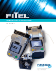
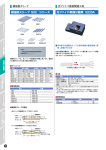
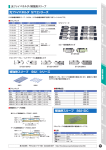
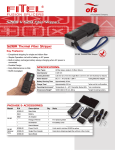
Fusion Splicers
A Furukawa Company
Cleaver
Stripper
Other Tools
FITEL® Fusion Splicers &
Tools Catalog
www.ofsoptics.com
Volume 1
FUSION SPLICERS
FUSION SPLICERS FOR OPTICAL FIBER
Optical fiber plays a critical role in today’s communication networks – from
telecommunications to CATV to data. Furukawa is a major manufacturer and
provider of high quality optical fiber and fiber optic products. This includes a
complete line of fusion splicers that produce highly accurate, reliable splices
with minimal loss. Furukawa’s fusion splicers are designed using state-of-the-art technology,
decades of manufacturing experience and feedback from countless customers.
You’ll find that FITEL splicers are simple yet precise and reliable tools that can support
your full range of fiber manufacturing, R&D, installation, and maintenance applications.
S122A/S122M4/
S122M8/S122M12
S177A/S177LDF
...page 8-11
...page 4-7
With its super low profile and new user interface,
the FITEL S122 series fusion splicer offers next
generation workability for every splicing field.
Combining the portability, power flexibility and
field ruggedness of FITEL’s previous generation
of hand-held splicers with the proven quality and
performance of our ribbon splicers, the S122 delivers fast and consistent splicing with outstanding
mobility and extreme ease-of-use.
The new hand-held FITEL S177A Fusion Splicer incorporates an improved heating design that cuts splice-to-heat
time by 40 percent, achieving a 9-second splice time and
37-second heat time. The unit’s T-shaped body design is
also 40 percent lighter, weighing only 4.85 pounds including
battery. Ideal for fast field use, the S177A reduces the fiber
length required for splicing by 30 percent. In addition, fiber
magnification power is 608X, making this the industry’s most
powerful core alignment splicer.
2
CONTENTS
Fusion Splicers
• Types of Fusion Splicers in the industry …………………… 4
• S122 SERIES Hand-Held Fusion Splicer …………………… 5
• S177A Hand-Held Core-Alignment Fusion Splicer ………… 8
• S177 Large Diameter Fusion Splicer …………………………10
• S183PM Advanced Fusion Splicer Series……………………12
• Connector Termination System ……………………………… 14
Cleaver
• Cleaver ……………………………………………………… 15
Stripper
S183PM
• S218R Thermal Stripper ………………………………………16
...page 12-13
Other tools
The S183 Full Function Fusion Splicer series provides you the ultimate splicing solution. Designed primarily to address production
and research splicing needs. This is the most advanced series
in FITEL’s extensive line of high performance machines. The
S183PM Splicer offers a total solution for precision polarization
maintaining fiber splicing. This model offers high strength splicing, specialty fiber splicing and attenuation splicing - all essential
processes when using Special Fibers.
• Fusion Splicer Accessories and Consumables ……………17
• ID-H/R Fiber Identifier ……………………………………… 20
• ID-L Light Source ………………………………………………21
• LBT-101 Short Range Optical Tester ……………………… 22
• CS201 Cable Sheath Strippers ……………………………… 24
OPTICAL FIBER SPLICING PROCESS
STRIPPING
CLEANING
CLEAVING
SPLICING
PROTECTION
16
17
15
4 - 14
19
Using a fiber
stripper to remove
the coating material
from the fiber.
Using alcohol and a
specially designed
wiper to clean the
bare fiber.
Using a precise
cleaver to cut the
fiber.
Using a fusion splicer to align
fibers & discharge the arc to
connect the fibers.
In addition, the unit will
inspect the quality of the splice
after the process.
Using a heat-shrinking
sleeve to protect
spliced fiber.
3
Types of Fusion Splicers in the Industry
Fusion Splicers
There are a number of ways to categorize splicers. Here we categorize them based on the fiber alignment type:
Fixed V-Groove alignment type and Core-Alignment type. The Fixed V-Groove is typically used for ribbon fiber
splicing. The Core-Alignment type is used for single fiber splicing with more precise requirements, such as optical
components manufacturing. With both types, the arc discharge is same.
RoHS
RoHS
RoHS
Type
S122A/S122M4
Alignment Type
Fiber
Observation
Applicable
Fiber
Fiber Count
S122M8/S122M12
S177A/S177LDF
Fixed V-Groove (Clad Alignment)
S183PM
Core Alignment
2 CCD Cameras
SMF, MMF, DSF,
NZDSF, EDF, DCF
SMF, MMF, DSF, NZDSF
S122M8: 1 ~ 8 Fibers
S122M12: 1 ~ 12 Fibers
S122A: Single Fiber
S122M4: 1 ~ 4 Fibers
SMF, MMF, PMF,*
NZDSF, EDF, DCF
Single Fiber
Cladding
Diameter
125µm
Coating
Diameter
Single: 250 µm, 900 µm
Ribbon: 280 µm ~ 400 µm
Single: 160 ~ 900µm
Cleave
Length
S122A, S122M4, S122M8, S122M12: 10 mm
250 µm: 5 ~ 16 mm
Normal strength: 9 ~ 11 mm
900 µm: 16 mm (10 mm option) High strength: 3 ~ 5 mm
No
Yes
No
Yes
S177A: 80 ~ 200 µm
S177LDF: 125 ~ 400 µm
Dissimilar
Splicing
Specialty
Splicing
High Stength
Splicing
Polarization
Maintaining
Splicing
Applicable
Sleeves
S122A, S122M4, S122M8, S122M12: 40 ~ 60 mm
Battery
Available
80 ~ 200 µm
No
Yes
No
Yes
20 ~ 60mm
S177A: Available
S177LDF: No.
No
* : S183PM only
ALIGNMENT TYPE
FIXED V-GROOVE (S122)
CORE ALIGNMENT (S183)
Aligning
Fiber
Aligning
Fixed V-Groove
Fiber
Moveable V-Groove
Micrometer
CORE ALIGNMENT (S177)
Fixed V-groove
2 way aligning
V-groove
Y
Z
X
Fiber feeding moving stage
4
Z
S122 SERIES Hand-Held Fusion Splicer
RoHS
With its super low profi le and new user interface, the FITEL S122 series fusion splicer
offers next generation workability for every splicing field, FT TX, LAN, backbone,
or long-haul installations. Combining the portability, power flexibility and field ruggedness of FITEL’s previous generation of hand-held splicers with the proven
quality and performance of our ribbon splicers, the S122 delivers fast and
consistent splicing with outstanding mobility and extreme ease-of-use.
Fusion Splicers
Key Features:
Superb Mobility and Workability
Super low profile design, with only 4.7cm height at the keypad, the S122 provides a stable working
environment both on the work bench and palmtop. Attaching the S122 to the Work Table (optional)
enables hands-free operation, as well as easy access to various work fields by folding the splicer
upward.
Rugged Body
The top body and windshield are made of magnesium die-cast. The bottom body is protected with
rubber corner pads. With its simple and flat shape, the S122 can survive during harsh conditions.
New GUI & LCD Screen
Featuring a new GUI (graphical user interface) and transreflective LCD screen technology, the
S122 operation is a snap! Function keys are simple and information displays are crisp and clear
even in direct sunlight.
Multi-Window Fiber Display
The LCD display shows the splicing process with simultaneous X and Y camera views, as well as
status icons monitoring the machine conditions.
Fast and Accurate
The fast 13-second splice time and 37-second heat time creates a highly efficient work environment. The S122 observes the fiber from 2 directions just as all high-end splicers, promising high
quality splice from trunk to FTTX.
Enhanced Ease of Use
Memory for fiber image, counters for cleaver and stripper blade replacement and visual maintenance instructions are provided for your ease of use.
Real Time Arc Control
Patented process which increases consistency and reduces splice loss. Also, virtually eliminates
the need for traditional arc checks by actively calibrating the arc during each splicing cycle.
Fiber Clamp Vibration System (S122M8 and S122M12 only)
New fiber clamp vibration system allows for easy fiver placement. System inspects axis offset
before each splice and makes necessary adjustment for ideal splicing.
Automatic Fiber Count Identification
Unit automatically identifies fiber ribbon count and selects the proper program for splicing. There
is no need to manually change the program when operators want to splice different fiber counts.
RoHS and Telcordia (GR-765-CORE for S122A, GR-1095-CORE for
S122M4 / M8 / M12) Compliant
FUSION SPLICERS
5
S122M8
S122M4
S122M12
Fusion Splicers
S122A
S122 Series
Product Line-Up:
Model
S122A
Application
S122M4
Splicing for single fiber to 4-fiber ribbon using Fiber Holder System
S122M8
Splicing for single fiber to 8-fiber ribbon using Fiber Holder System
S122M12
Splicing for single fiber to 12-fiber ribbon using Fiber Holder System
Splicing for single fiber using Fiber Holder System / Splice-On Connector Ready
Specifications:
Fiber Types
SMF, MMF, DSF, NZDSF
Cladding Diameter
125 µm
Coating Diameter
250 µm to 900 µm for single fiber
280 µm to 400 µm for ribbon (thickness) [S122M4. S122M8. S122M12]
Average Splice Loss
SMF: 0.05 dB, MMF: 0.03 dB, DSF: 0.08 dB, NZDSF: 0.08 dB
Splice Time
13 sec. (S122A), 15 sec. (S122M4. S122M8. S122M12)
Heat Time
Single Fiber: 37 sec. (40 mm), 51 sec. (60 mm),
Ribbon Fiber: 45 sec. (40 mm)
Tension Test
1.96 N
Applicable Sleeve Length
40/60 mm
Program Memory
Splice Programs: Max. 150, Heat Programs: Max. 12
Splice Memory
Max. 1,500 (S122A. S122M4), Max. 1,000 (S122M8. S122M12)
Fiber Image Display
Simultaneous two-axis display
Magnification 120X (S122A), 48X (S122M4), 28X (S122M8), 20X (S122M12)
Dimensions
140W × 189L × 73H mm (S122A. S122M4),
140W × 189L × 86H mm (S122M8. S122M12)
Weight
800g / 1.8lb. (S122A. S122M4),
960g / 2.1lb. (S122M8. S122M12),
170g / 0.4lb. (battery)
AC Input
100 to 240 VAC
DC Input
10.6 ~ 12.6 V
Battery Capacity
50 splices with heat shrink protection (S122A. S122M4)
40 splices with heat shrink protection (S122M8. S122M12)
Operating Temp.
-10° C to + 50° C
Storage Temp.
-40° C to + 60° C
6
S1
22
S1 A
22
S1 A2 2 K IT
S1 A-K -1
2 2 IT
S1 M4 -2
22
S1 M4
22 - K
M IT
4 - -1
K
IT
-2
Packages
Description
S122-A-A-0001
S122A Splice Body
S122-M-A-0001
S122M4 Splice Body
S122-X-A-0002
Soft Carrying Case
•
•
S122-X-A-0003
Strap
•
•
S122-X-A-0005
Hard Carrying Case
S211B
Fiber Stripper
S218R
Thermal Fiber Stripper
S325A
One-Action Precision Cleaver
S709A-004
4-Ribbon Fiber Holders (pair)
S709S-250
250mm Fiber Holders (pair)
S709S-900
900mm Fiber Holders (pair)
S943
Li-ion Battery
S943
Extra Li-ion Battery
S957B
AC Adapter
•
•
•
•
•
•
S958B
Battery Recharger
•
•
•
•
•
•
S959U
DC Adapter
S966
Electrodes (pair)
•
•
•
•
•
•
D5111
Electrode Cleaning Disk
•
•
•
•
•
•
FPF-01
Fiber Preparation Fluid
•
•
•
•
FW-01
Fiber Wipes
•
•
•
•
FTS-B291
Manual
•
•
•
•
•
•
•
•
Description
S122-X-A-0004
Working Table
S709A-002
2-Ribbon Fiber holders (pair)
S945
High Capacity Battery
CS202
Sheath Stripper
SS-01
Splicer Scissors
•
•
•
•
•
•
•
•
•
•
•
•
•
•
•
•
•
•
•
•
•
•
•
•
•
•
•
•
•
•
•
•
•
•
•
•
•
•
•
•
•
Optional Accessories
P/N
•
7
Fusion Splicers
P/N
S177A Hand-Held Core-Alignment Fusion Splicer
Seamless Splicing from Trunk to FTTX
Fusion Splicers
Key Features:
• Most compact, lightweight core-alignment splicer in the industry!
• New graphical user interface (GUI) to enhance ease-of-use.
• Transreflective LCD allows clear view even in direct sunlight.
• Best-in-industry fiber magnification-680X.
• Built-in battery automatically charges when plugged into AC-even
when splicing!
• RoHS and Telcordia (GR-765-CORE) compliant
Specifications:
Splicing Method
Core-Alignment
Applicable Single Fiber
SMF, MMF, DSF, NZDSF, EDF
Average Insertion Loss
SMF: 0.02 dB, MMF: 0.01 dB, DSF: 0.04 dB, NZDSF: 0.03 dB
Splice Time
9 sec
Heat Time
37 sec (40 mm), 51 sec (60 mm)
Splice/Heat Programs
150 available / 12 available
Cleave Lenght
5-16 mm (250 µm), 10 or 16 mm (900 µm)
Dimension/Weight
130 W×260 D×137 H mm / 2.20 kg (4.85 Ibs) [weight including battery]
Splice Memory
2000 splices
Operating Enviroment
0~4,000 m, -10 to +50° C and 90% at 38° C
Data Output
USB 1.1
Battery Life
Internal - 70 splice / heat cycles
Power
AC Input : 85 to 264 V (50/60 Hz), DC Input : 11 to 17 V, Battery : Li-ion
FUSION SPLICERS
8
RoHS
Seamless Splicing from Trunk to FTTX
The FITEL S177A ushers in a whole new range of applications for core-alignment splicing : It delivers the same precision, accuracy, and automated functionality of a conventional core-alignment
unit, but with the speed, portability, and covenience of a hand-held splicer. The S177A becomes
your versatile best choice for FTTX, LAN, backbone, or long-haul installations.
Fusion Splicers
Compact, Lightweight Body
At nearly half the weight and size of FITEL's standard core-alignment
unit, the S177A weight only 2.2 kgs (4.85 lbs) – making it the first
hand-held and most compact, lightweight core-aligning splicer in the
industry. The T-shaped body design, measuring just 5 inches across,
easily accommodates short fiber lengths. The magnesium alloy canopy
and top base provide the rugged strength required for field operations.
Highly accurate, it easily handles diverse applications-from trunk splicing to FTTX.
New GUI & LCD Screen
Featuring a new GUI (graphical user interface) and transreflective LCD screen technology, the
S177A operation is a snap! Function keys are simple and information displays are crisp and clear
even in direct sunlight. The LCD display shows the splicing process with simultaneous X and Y
views, Fiber magnification is the highest available in the industry - 608X, and over 200 percent
stronger then FITEL's previous model, the S176.
Standard Package:
Optional Accessories:
P/N
Description
P/N
Description
S177-X-A-0001
Splicer Body
S177-X-S-0005
Cooling Tray
S177-X-S-0002
Spare Electrodes
S177-X-S-0006
USB Cord
S177-X-A-0003
Carrying Case
S177-X-S-0007
Fiber Holder Mount
S943
Internal Battery
S707S-080
80µm Fiber Holder
S957
AC Adapter
S707S-250
250µm Fiber Holder
D5111
Electrode Cleaning Disk
S707S-900
900µm Fiber Holder
S177-X-S-0004
Manual
S707S-400
400µm Fiber Holder
S210
Furukawa Fiber Stripper
S211
Miller Stripper
S325A
Hand-Held High Precision Cleaver
ORDERING NUMBER FORM:
S177AFiber Holder Type
Cleave Length
0: 16mm Tight Holder
125 / 250 µm: 5 ~ 16 mm; 125 / 900 µm: 16 mm
1: 10mm Tight Holder
80 / 150 ~ 200 µm: 5 mm; 125 / 250 µm: 5~10 mm; 125 / 900 µm: 10 mm
2: Fiber Holder System
SOC Applicable
80 / 150~200 µm: 5 mm; 125 / 250 ~ 900 µm: 10 mm
3: Loose-Tube-Holder
125 / 250 µm: 5 ~ 10 mm
9
S177 Large Diameter Fusion Splicer
Fusion Splicers
The FITEL S177LDF Large Diameter Fusion Splicer builds upon the robust performance of the proven S177A Splicer and expands its capabilities to splice up to 400 μm
cladding fiber. The unique design effectively blends fusion splicing with portability, speed, and the ease of operation of FITEL's S177 series machines.
Specifications:
Splicing Method
Active Clad-Alignment
Applicable Optical Fiber
SMF
Fiber Cladding Diameter
125 ~ 400 µm
Fiber Coating Diameter
250 ~ 900 µm
Cleave Length
10 mm
Splice Loss (Typical)
0.04 dB (Furukawa identical 125 µm-SMF)
Splice Time
16-second for 125 µm SM fiber
26-second for 400 µm LDF
Heat Time
37-second for 40mm protection sleeve
51-second for 60mm protection sleeve
Dimensions
130 W × 260 D × 137 H mm
Weight
2.0 kg
AC Power
AC Input : 100 to 250 V (50/60 Hz)
FUSION SPLICERS
10
RoHS
Key Features:
The S177LDF Splicer is able to splice from 125 μm to 400 μm cladding fiber as
well as to splice different diameter fibers for 400 μm and 125 μm. These highend splices are provided with small, light and fast, easy to use and low cost S177
series fusion splicer.
Like other Furukawa fusion splicers, featuring GUI (graphical user interface),
the S177LDF operation is a snap! Function keys are simple and information displays are crisp and clear.
Standard Package:
P/N
Description
Qty
S177L-A-X-0001
S177LDF Main Body
S707T-600
Fiber Holders
1 set
S968
Spare Electrode
1 pair
S177-X-A-0003
Hard Carrying Case
1
S971
AC Adapter
1
D5111
Electrodes Cleaning Disk
1
Operation Manual
1
Note
1
Applicable Coating
Diameter: 250 ~ 900 µm
Manual
11
Fusion Splicers
An upgraded high voltage Arc Discharge
Unit provides the power necessary for
LDF splicing. A wide field of view camera and advanced optical design expands
the viewing range of the proven S177A
design. These two capabilities allow for
automated active LDF alignment while
maintaining the precision of conventional 125 μm splicing.
S183PM Advanced Fusion Splicer Series
Fusion Splicers
Take Splicing to the Next Level & Beyond!
The S183 Advanced Fusion Splicer series was designed specifically for the demanding
production and research applications of the optical components industry. The S183PM
Advanced Fusion Splicer offers programs for specialty and exotic fiber combinations
as well as high-strength splicing applications. This splicer can also splice polarization maintaining fiber faster than any other unit in the world. The S183
Advanced Fusion Splicer series is setting a new standard in the field
for high-end fusion splicing applications.
Features & Applications:
Specialty Splicing Made Easy
The advanced features of the S183 allow you to splice today's and tomorrow's most exotic fiber types.
Whether performing high-strength splices, splicing small cladding fibers (80 µm), large cladding fibers
(200 µm), high MFD Δ splicing combinations, PM fibers, or erbium doped fiber, the S183 is the splicer for
your high-end application.
Fast Splice Time!!
The splice time is lightning fast at 42 seconds for PANDA
and 20 seconds for SM. The S183 is the fastest in the
industry for most fiber applications, allowing you to increase
efficiency on your production line.
Safe PM Fiber Rotation
The new rotation mechanism on the S183PM Splicer allows PM fiber to rotate while keeping straight and stable.
This minimizes fiber twist, which can be detrimental to sensitive splicing
applications.
Quick Loading & Automatic Machine Adjustment
The S183 Splicer automatically adjusts for different fiber coating and cladding sizes. There is no need
to exchange electrodes, v-grooves, or fiber clamps. In addition, the S183 Splicer has been designed so
that the user simply loads the fiber and closes the lid to begin the fusion process. There is no need to
lower or set fiber clamps before beginning your splice.
Automatic Fiber Holder Release
The S183 automatically performs a tensile proof test on the fiber and releases the holder lid to avoid
twisting the fiber after the splice. This automation eliminates the need for the user to manually open and
reset the splicer after each fusion splice.
12
Specifications:
SMF, MMF, DSF, NZDSF, CSF, DCF, EDF, PMF
Fibers Cleave Length
3 to 5 mm with coating clamping / 9 to 11 mm with bare Fiber clamping
Cladding Diameter
80 ~ 200 µm
Coating Diameter
160 ~ 900 µm
Typical Insertion Loss (Similar Fiber Splicing)
0.02 dB for identical SMF / 0.01 dB for identical MMF
0.04 dB for identical DSF / 0.05 dB for identical PM Fibers
Typical Insertion Loss (Dissimilar Fiber Splicing)
0.05 dB for SMF to PANDA Fiber / 0.10 dB for SMF to TIGER Fiber
0.15 dB for SMF to BOW-TIE Fiber / 0.10 dB for PANDA Fiber to TIGER Fiber
Typical Extinction Ratio
(Cross Talk)
(Similar Fiber Splicing)
-40 dB (0.6 degree) for identical PANDA Fibers
-32 dB (1.4 degree) for identical TIGER Fibers
-32 dB (1.4 degree) for identical BOW-TIE Fibers
Typical Extinction Ratio
(Cross Talk)
(Dissimilar Fiber Splicing)
-32 dB (1.4 degree) for PANDA Fiber to TIGER Fiber
-30 dB (1.8 degree) for PANDA Fiber to BOW-TIE Fiber
Loss Estimation Parameters
Cleave angle, Fiber Offset, Tilt, Micro-bending, Fiber end gap, Bubbling at splice point
Dimensions / Weight
Return Loss
350 W × 197 D × 154 H mm / 8.7 kg
20 seconds for identical Single-Mode Fibers
42 seconds for identical PM Fibers (cladding clamping)
60 seconds for identical PM Fibers (coating clamping)
90 seconds for 60 mm sleeves
95 seconds for 40 mm sleeves
40 seconds for 25 mm sleeves
> 60 dB
Tensile Strength
Typical 300 kpsi (25 N) with High strength splice
Magnification
133X & 266X
Monitor
5" 8-color LCD monitor.
Video Output
PIN
Data Interface
Serial, USB ver1.1, and Ethernet
Splice Programs
55 Default / 150 Available
Splice Memory
Maximim 2000 splices
Operating Temperature
0 to +40° C (without excessive humidity)
Storage Temperature
-40 to +60° C (without excessive humidity)
Power Source
AC 100 to 240V (50 / 60 Hz)with AC adaptor
Splice Time
Heating Time
S183 Standard Package:
Fusion Splicers
Applicable Fibers
S183 Optional Accessories:
P/N
S183-P-A-0001
Description
S183PM Main Body
Qty
1
S710S-080
160 µm Coating Fiber Holders
1 pair
S710S-250
250 µm Coating Fiber Holders
1 pair
S710S-400
400 µm Coating Fiber Holders
1 pair
S710S-900
900 µm Coating Fiber Holders
1 pair
S183-X-A-0002
Fiber Transporter
1
S183-X-S-0003
AC Adaptor
1
S183-X-S-0004
AC Power Cord
S183-X-S-0005
Spare Electrodes
1
1 pair
Electrode Sharpener
1
User's Manual
1
13
P/N
S325A
Description
High Precision Cleaver
S325S80
High Precision 80 µm Cleaver
Qty
1
1
Splice-On Connector Termination System
Fusion Splicers
Description:
FITEL’s new connector termination system allows for unsurpassed performance and
flexibility in the field. This new “splice-on” connector eliminates the need for field
polishing and significantly improves the quality of the termination and installation time required. FITEL’s factory polished ferrules with pre-cleaved fiber stubs
are spliced onto the field fiber utilizing FITEL’s proprietary ferrule holder and fusion
splicer. The connector is easily assembled by using a process that requires minimal
skill or training.
• Both single-mode and multimode versions are available.
Technical Information - Splicer:
Type
Splicing Method
Fiber Type
Insertion Loss
Battery Capacity
Applicable Sleeves
S122A
Technical Information - Connector:
Type
S177A
Clad-Alignment
Core-Alignment
SMF, MMF, DSF, NZDSF
SMF, MMF, DSF,
NZDSF, EDF, etc.
Typical 0.05 dB (SMF)
Typical 0.02 dB (SMF)
50 splice cycles
70 splice cycles
20 - 60mm
20 - 60mm
SC/Ultra PC; FC/Ultra PC SC/Angled PC; FC/Angled PC
Insertion Loss
Reflectance
Typical 0.30dB
< - 55 dB
Fiber Type
< -65 dB
SMF
Jacket Type
900 µm, 2 mm, 3 mm
Ferrule Type
Zirconia ceramic ferrule with pre-polished fiber stub
Features & Applications:
• Simple, Fast, & Consistent Field Termination
• Fiber Management
Allows for easy field repair of pre-terminated splitters, fan outs,
and drop terminals.
The most difficult task for splicer operators has always been
managing the fiber upon completion of splicing. The connector
termination feature on the S177A eliminates the need for splice
trays resulting in easier fiber management, reduced storage
requirements, and faster installation times.
• No Polishing or Epoxy
FITEL’s connector termination process requires no polishing or
epoxy increasing the quality and consistency of field connector
termination. Total installation time is greatly reduced compared
to traditional methods.
900 µm CONSTRUCTION
2 & 3 mm CONSTRUCTION
CONNECTORS
Ordering Information
P/N
Description
S707C
S325A
S240A
SS-01
S211B
CRP-01
SSCS-PN1
SSCS-PN2
SSCS-PN3
SSCS-P1
SSCS-P2
SSCS-P3
SAPS-388
SAPS-386
SAPS-387
SAPS-358
SAPS-356
SAPS-357
SOC Fiber Holder for S177A-02
S325A Hand-Held High Precision Cleaver
S240A Slitter Snapper
SS-01 Splicer Scissors
S211B 3-Hole Fiber Stripper
CRP-01 SOC Crimp Tool
SC/APC Splice-On-Connector, 900 µm
SC/APC Splice-On-Connector, 2 mm
SC/APC Splice-On-Connector, 3 mm
SC/UPC Splice-On-Connector, 900 µm
SC/UPC Splice-On-Connector, 2 mm
SC/UPC Splice-On-Connector, 3 mm
FC/APC Splice-On-Connector, 900 µm
FC/APC Splice-On-Connector, 2 mm
FC/APC Splice-On-Connector, 3 mm
FC/UPC Splice-On-Connector, 900 µm
FC/UPC Splice-On-Connector, 2 mm
FC/UPC Splice-On-Connector, 3 mm
RoHS
S122A
RoHS
SOC CONNECTORS
S177A-02
14
Cleaver
One-Step Cleaving... In the Palm of your Hands
S325A Hand-Held High Precision Cleaver
Key Features:
• One-Step Action
• Cleave Anywhere! - In Your Palm or on Your Desktop
• Easy Fiber Loading
• Simple Operation
• High Capacity Waste Fiber Collection
• Durable Design
• Easy Maintenance on-Site
Fiber Types
All fiber types, single to 12-fiber ribbons
Clad Diameter
0.125 mm
Coating Diameter
0.25 mm and 0.9 mm for single fiber; 0.3 mm to 0.4 mm thickness for ribbons
Cleave Length
Single Fiber: Fixed Length - 10 & 16 mm Variable Length - 3 to 20 mm
Ribbon Fiber: 10 mm Fixed Length
Dimensions/Weight
93 W × 68 D × 52 H mm, 330 g
* S325S80 High precision cleave for 80 µm cleaving is also available.
Standard Components:
P/N
Description
Qty
S325X-01
Main Body
1
S325X-02
Soft Carrying Case
1
S325X-03
Normal Fiber Waste Bin
2
S325X-04
Single Fiber Adapter
1
S325X-05
Large Capacity Fiber Waste Bin
1
FTS-B277
User's Manual
1
S310 and S315 Single Fiber
Applicable Optical Fiber:
Silica glass-based optical fibers, single fiber, 0.25 mm and 0.9 mm
coating diameter, 0.125 clad diameter.
Cleavers
The FITEL S310 and S315 Single Fiber Field Cleavers are designed for
cleaving fiber in the field quickly and easily. The S310 and S315 Field
Cleavers can accommodate 0.25 mm and 0.9 mm coating diameters
and their small lightweight size makes them the perfect addition to any
field splicing system. The S310 and S315 Field Cleavers require some
skill to achieve the desired cleave angle and may not be appropriate for
some splicing applications. The S310 is specifically designed to cleave
fiber in the field accurately to a 16 mm length. The S315 Cleaver has a
graduated scale, which allows for cleave lengths of 5 to 20 mm.
Models:
S310 : For cleaving to 16 mm length
S315 : For cleaving 5 to 20 mm length adjusting with scale
Dimensions 20 W × 125 D × 42 H mm
Weight
15
65 g
Fusion Splicers
Specifications:
S218R Thermal Stripper
RoHS
New & Improved !!
Cordless, Light, & Quick
Key Features:
• Exceptional stripping for single and ribbon fiber
• Simple Operation via built-in battery or AC power
• Built-in battery recharger-battery always charging
when AC power is connected
• Durable Design
• Easy Maintenance on-Site
• RoHS Compliant
Stripper
Specifications:
Fiber Types
All fiber types, single to 12-fiber ribbons
Clad Diameter
0.125 mm
Coating Diameter
0.25 mm to 0.4 mm for single fiber; 0.3 mm to 0.4 mm thickness for ribbons
Power Source
DC 11 ~ 14V
Battery Running Time
Approximately 10 hrs.
Charge Time
Approximately 2.5 hrs.
*when unit is in off position
Operating Environmet
Temperature: 0 ~ 40° C Humidity: Below 95%
*non-condensing
Dimensions/Weight
125 W × 48 D × 41 H mm, 260 g
*weight including battery
AC 85~264 V
*using S952 AC Adapter
Package & Accessories:
Model
S218R
S218R
Optional
Parts
P/N
Description
S218R-01
Main Body
Qty
1
Note
S944
Battery
1
S952
AC Adapter
1
-
Hexagon Wrench
1
For replacing blade
-
Screwdriver
1
For battery cover
-
User's Manual
1
S218X-02
Power Cord A
1
Cord used to connect S218R to splicer
S218X-03
Single Fiber Adapter
1
Used when stripping single fiber without a fiber holder
S218X-06
Spare Blade
1
S210 Single Fiber Stripper
Applicable Optical Fiber:
The FITEL S210 Single Fiber Stripper is designed to strip 0.25 mm as
well as 0.9 mm diameter fiber. This easy to use stripper has a 20 mm
wide base with the blade located in the
center to ensure safe longitudinal stripping.
Silica glass-based optical fibers, single fiber, 0.25mm and 0.9mm
coating diameter, 0.125 clad diameter.
Dimensions 20 W × 80 D × 26 H mm
Weight
16
70 g
Fusion Splicer Accessories and Consumables
S42X Fusion Splicer Tool Kits
The S42X Series Fusion Splicer Tool Kit contains all of the necessary tools
required for optical fusion splicing in a rugged carrying case. The durable
carrying case features separate compartments for organizing tools and consumables.
Description
Model
Qty
S422
S423
S424
○
○
○
○
○
○
○
○
○
○
○
○
○
○
○
○
○
○
1
Precision screw driver set and hexagonal
wrench set
○
○
○
1
Electrode sharpener
○
○
○
○
2
S210 Single Fiber Stripper
Carrying case
250 cc Polyethylene bottle with siphon
Cleaning cotton for optical fiber
Cotton stick for cleaning V-groove, lens, mirror
Blower brush for cleaning V-groove, lens, mirror
S310 Single Fiber Cleaver
S325A High Precision Cleaver
1
1
1
1
1
1
○
○
○
S218R Thermal Stripper
1
1
S220A Optical Ribbon Fiber Separator
Designed to initiate separating 2 to 12-fiber ribbons into single fibers.
After shaving with S220A Separator, the ribbon fiber can be easily separated by
fi ngers into single fibers. Compact carrying case included as standard.
2 to 12 fiber ribbons with the thickness of 0.30 ~ 0.40 mm
Dimensions
55 W × 30 D × 42 H mm
Weight
100 g
Caution
Do not use the S220A Separator on live fiber or for a mid-span strip.
Discard the section of the fibers to which the S220A Separator was applied before splicing or reconnecting the exposed fibers.
FUSION SPLICERS
17
Model
Description
Qty
S220A
Fiber Separator
1
FTS-B013
User's Manual
1
Accessories & Consumables
Applicable Optical Fiber:
Fusion Splicer Accessories and Consumables
S233 Optical Ribbon Fiber Splitter
FITEL S233 Ribbon Splitter splits 4, 8, 12,and 24-fiber ribbons more
easily, quickly, and accurately than ever before! Another great FITEL
fusion splicing accessory from OFS!
Key Features:
• Small, simple, and compact design for field use.
• All-metal body for maximum durability.
• Interchangeable fiber guides for different ribbon sizes.
• No tools required to change fiber guides!
Models : (see below for Fiber Guide descriptions)
Applicable Optical Fiber:
125 µm cladding diameter; 4/8/12/24-fiber ribbons; 0.25 mm pitch; 0.30 to
0.40 mm thickness; UV-cured acrylic resin coating*
* S233 may not work satisfactorily with some ribbon fiber coating materials.
Caution:
Do not use the S233 on live fiber or for a mid-span strip. Discard
the section of the fibers to which the S233 was applied before
splicing or reconnecting the exposed fibers.
Dimensions 115 W × 20 D × 20 H mm
Weight
S233A : Fiber Guide A is included as standard
S233B : Fiber Guide B is included as standard
S233C : Fiber Guide C is included as standard
95g
Standard Package:
Description
P/N
Qty
Note
Model
S233A
S233B
S233C
○
○
○
○
○
○
○
○
○
Main Body**
S233X-01
1
All-metal base body for all fiber guides
Cleaning Brush
S233X-02
1
Tool to remove fiber jacket waste
Carrying Case
S233X-03
1
Clear; holds all standard components
Fiber Guide A
S233X-11
1
Obverse: 4-fiber ribbon > 2 x 2-fiber ribbons
Reverse: 4-fiber ribbon > 3-fiber ribbon & single-fiber
○
─
─
Fiber Guide B
S233X-12
1
Obverse: 4-fiber ribbon > 2 x 2-fiber ribbons
Reverse: 8-fiber ribbon > 2 x 4-fiber ribbons
─
○
─
Fiber Guide C
S233X-13
1
Obverse: 12-fiber ribbon > 2 x 6-fiber ribbons
Reverse: 24-fiber ribbon > 2 x 12-fiber ribbons
─
─
User’s Manual
S233X-82
1
User's Manual
○
○
○
○
** Not sold individually
Accessories & Consumables
S91X Temporary Fiber Aligner
Designed as a jig for temporary jointing the fibers for measuring
transmission loss or for experimental purposes. A simple procedure to strip, clean, cleave and load the fiber makes a temporary
jointing with a typical average loss of 0.25 dB for SM fiber (when using
matching oil).
Item
P/N
Qty
Main Body
S91X
1
—
1
User's Manual
Model
Specifications:
Dia. of Applicable Fibers
Qty
S911
0.90 × 0.90
1
Fiber Type
SMF, MMF (Single Fiber)
S912
0.90 × 0.40
1
Insertion
0.25 dB (with maching gel)
S913
0.40 × 0.40
1
Dimensions 50 W × 55 D × 33 H mm
S914
0.40 × 0.25
1
Weight
S915
0.25 × 0.25
1
S916
0.25 × 0.90
1
350 g
18
S918A Temporary Fiber Aligner
Designed to make the time-consuming job of testing ribbon fiber quicker and easier, the
S918A allows the user to create a temporary connection of single to 12-ribbon fibers.
Specifications:
Fiber Type
Silica glass-based optical fiber
Ribbon Count
Cleave Length
2-12 Fiber Ribbon
250 µm-900 µm Single Fiber
300 µm-400 µm Ribbon Fiber (250 mm pitch)
100 mm
Typical Loss
0.2 dB (using matching gel)
Pushing Mechanism
Manual dial wheel
Light
Switch turns light on in magnification area
Body : 131 W × 90 D × 58 H mm
Case : 385 W × 270 D × 95 H mm
Body : 540 g
Coating
Dimensions
Weight
Optional Accessories:
Fiber Holders :
The fiber holders to meet your fiber type are required from the following selections.
Standard Components:
Applicable Fibers
P/N
(Number of fibers/Diameter or Ribbon Thickness)
Description
Model No.
Single/0.25 mm
Main Body
S918A-01
1
Single/0.9 mm
Light
S918A-02
1
S706A-002
2-fiber ribbon/0.4 mm
Matching Gel
S918X-31
1
S706A-004
4-fiber ribbon/0.4 mm
Bamboo Pick
S918X-32
5
S706A-008
8-fiber ribbon/0.4 mm
Case
S918X-33
1
S706A-012
12-fiber ribbon/0.4 mm
User’s Manual
—
1
S706S-025
S706S-090
S612 Ribbon Forming Fixture
Qty
Specifications:
Designed to form a ribbon-like fiber with 2 to 12 single
fibers. S612 Ribbon Forming Fixture
offers a high efficient simultaneous
fiber splice with FITEL ribbon
fusion splicers.
Applicable optical fiber
2 to 12 fiber ribbons
Dimensions
120W×60D×58H mm
Weight
400g
Standard Components:
• Easy to operate.
• Smallest fi xture in
the industry.
• Consumables are adhesive only.
Description
Model No.
Ribbon forming fixture
S612
Adhesive
S611-04
User's Manual
FTS-B010
FITEL offers a wide variety of protection sleeves to accommodate single and ribbon
fiber. FITEL's protection sleeves come in ribbon, standard, slim, mini, and
macro sizes. They are composed of an outer an inner sleeve reinforced by
an internal member made of stainless steel or ceramics.
Model, Specification & Applicable Fiber:
Material of
Pieces/
strength member pack
Stainless steel
25
Model
Applicable fiber
Length
S921
Single fiber, 0.25-0.9 mm coating diameter
60 mm
S922
Single fiber, 0.25-0.9 mm coating diameter
40 mm
Stainless steel
S924
Single fiber and up to 8-fiber ribbon
40 mm
Quartz
25
S927A
Single fiber and up to 8-fiber ribbon
40 mm
Ceramic
100
S927B
Single fiber and up to 12-fiber ribbon
25
40 mm
Ceramic
100
S928A20
20 mm
Stainless steel
100
S928A25 Single fiber 0.25-0.4 mm coating diameter
25 mm
Stainless steel
100
S928A35
35 mm
Stainless steel
100
19
1
50 ml x 2 bottles
1
Accessories & Consumables
Protection Sleeves
Qty
ID-H/R Fiber Identifier
RoHS
The FITEL ID-H/R is a rugged, user-friendly tool which identifies optical fibers by detecting the optical signals passing through the fiber utilizing local detection technology.
The feature and benefits are:
Features:
• Wide dynamic range
• No Head changing or adjustments
• LCD screen adoption
(Detection Light Level, Modulation Light Frequency, Machinery Information)
• Detects the signal without disrupting traffic
• Detects the tone signal and traffic signal
• Lighted LED displays for clear identification
• Lightweight design for easy handling
• Super low insertion loss
• RoHS Compliant.
Example of Application:
Standard Components:
Transmission
Apparatus
Item
Code
Note
Main Unit
AI02H
Battery and Strap and
Instruction manual are
included
Carrying Case
AI02H-001
Easily to belt or
tool pouch
Live Fiber
Distribution
Frame
Closure
Optical Fiber
Cable
Direction of signal
Dark
Fiber
Light
Source
ID-H/R
ID-H/R
ID-L
Launching tone
signal to
the contrast finder.
Detecting the tone signal, the fiber optic
identifier emits continuous sounds and
directional LED arrows are illuminated to
show the Signal direction and Tone
signal using the illuminated LED display.
Identifies the dark fiber
In the cace of deteciting the traffic
sighal, the fiber optic identifier emits
intermittent sounds and directional
LED arrows are illuminated.
Differentlates the type of signal
by intermittent buzzer sounds.
Make sure to launch tone signal to the dark fiber and confirm the detection before disconnecting it.
Specifications:
Up to SM 12-fiber ribbon
SM 250 µm single fiber
Applicable Fiber
Up to 3 mm Cordage
(built-in only SM 250 µm single fiber)
Applicable Wavelength
900~1700 nm
270Hz and 1kHz and 2kHz (Duty ratio 50±10%) Modulation Light
No Modulation Light
Communication Light that Continued
Frequency for Tone Signal
Other Tools
Measurement Range of Optical Power *1
Maximum Level of
Insertion Loss
(Typical)
Average Minimum
Detection Level *2
(Typical)
SM 900 µm tight buffer
(Reference value)
0 ~ -80 dBm
1310 nm
0.1 dB
0.5 dB
1550 nm
1.0 dB
2.0 dB
1650 nm
2.5 dB
3.0 dB
1310 nm
-40 dBm
-30 dBm
-50 dBm
-40 dBm
1550 nm
1650 nm
Indication for Traffic Signal or Tone
Signal
-15 dBm
[ Traffic Signal *3] Direction LED illuminates + Intermittent buzzer sound + Displayed an Optical
power measurement range by LCD
[ Tone Signal ] Direction LED illuminates + Tone LED illuminates + Continuous buzzer sound +
Displayed an Optical power measurement range by LCD + Displayed Frequency by LCD
Operating Time
8 hours (Using alkaline battery)
Dimensions
40 W×65 D×153 H mm
Weight
160 g (Including battery)
*1: Duty ratio 50% *2: This specification is based on our optical fiber with our test method. *3: DO NOT disconnect or rewire based only on
the traffic signal detection. Make sure to launch the tone signal before disconnecting or rewiring the fiber.
20
ID-L Hand-Held Light Source
RoHS
Features:
• 4 Wavelength Lineup
1310 nm/1490 nm/1550 nm/1610 nm
• Boost Function
Activating the BOOST function increases the output signal by 10dB
• Selection of 4 frequencies
CW/270 Hz/1 kHz/2 kHz
• Lightweight design for easy handling
• Operate more than 60 hours on battery
With Alkaline battery at 23° C / Without using boost function
• Removable Adapter For Easy Cleaning
• RoHS Compliant
CLASS1 LASER PRODUCT
Example of Application:
ID-H/R (Optical Fiber Identifier) detects tone signal from ID-L
(Hand Held Light Source) to identify a target fiber.
Transmission
Apparatus
Optional Accessories:
Item
Code
Note
Carrying Case
AT03H-001
—
SC Adapter
AT03H-002
Standard Accessory
FC Adapter
AT03H-003
—
Distribution
Frame
Closure
Optical Fiber
Cable
Live Fiber
Direction of signal
Dark
Fiber
Light Source
ID-L
ID-H/R
ID-H/R
Specifications:
Product name
Code
Wavelength
ID-L Handy Light
Source 1310nm
ID-L Handy Light
Source 1490nm
AT03H31
AT03H49
AT03H55
AT03H61
1490±10 nm
1550±10 nm
1610±10 nm
Single Mode Fiber
Spectrum width
Less than 1nm (-20 dB from peak power)
CW / 270Hz / 1 kHz / 2 kHz
Normal: -2.5±2 dBm Boost: +7.5±2 dBm (3 dB down at 270 Hz,1 kHz, 2 kHz mode)
Stability
±0.05 dB (1 hour / Constant temperature)*
Optical connector
SC Adapter (FC adapter is option)
Battery type
AA Battery (Alkaline / Zinc-carbon / NiMH)
Battery life
Over 60 hours (Alkaline battery at 23° C)
Auto shutdown
10 minutes without any operation
Operating temp.
0 to 40° C
Operating humidity
20 to 90% RH (non-condensing)
Dimensions
70 W×22.5 D×128 H mm
Weight
160 g (Including batteries)
Strap: 1
AA alkaline batteries: 2
21
SC adapter: 1
Instruction manual: 1
Other Tools
Modulation
Accessories
ID-L Handy Light
Source 1610nm
1310±10 nm
Fiber type
Output power
ID-L Handy Light
Source 1550nm
LBT-101 Short Range Optical Tester
RoHS
Measurement Tool for Live Fiber testing of FTTX. 1610 nm OTDR for short Distance testing with Built-in Optical Filter.
Live Fiber Testing
1610 nm light source and built-in Optical Filter realized the test of live fiber of PON system! First in the industry!
Key Features:
Live Fiber Testing *1
Enabled live fiber testing by launching 1610 nm wavelength, (1310 nm/
1490 nm/1550 nm).
Portable
LBT-101 is a lightweight, handheld, user-friendly tool. Easily held in
one hand.
Easy Operation
Just pressing "START" button and it will start. Easy to operate for less
experienced user.
High Resolution
5 cm distance resolution. 2m dead zone.
Built-in Fiber
Measurable from the first connector.
Wide Screen
Real Time Sweeping
Full color 4.3" wide screen, which provides high visibility, both indoor
and outdoor.
Real time sweeping to identify target fiber.
Data Storage
Long Battery Life
Internal data storage is 40 MB (up to 800 traces). Also supported by
external USB memory.
Typically 3.5 hours by single charge.
RoHS compliant
*1 : The confirmation that there is no influence on the actual communication system is necessary.
CUT!
1490nm
Communication Light
1550nm
Communication Light
Good!
1610nm Test Light
ACTIVE FIBER
Other Tools
LBT-101
Optical
Filter
OLT
1490nm
Splitter
1310nm
1550nm
PON SYSTEM
22
Last Mile
Manufacturer:
SEIKO GIKEN
Specifications:
Wavelength*1
1610 ± 5 nm
Fiber Type
10/125 µm SMF (ITU-T G.652)
Built-in Fiber
Distance Range
10m
*2
1.0 km (3,000 ft) or 2.5 km (8,000 ft) set automatically
Pulse width
15 ± 3ns
Dynamic Range
> 6dB
Deadzone
Fresnel: <2 m *3, Backscatter: < 7 m *4
Data Storage
Internal memory: 40 MB (up to 800 traces), External (USB): up to 20,000 traces with 1 GB
Dimensions
190 W × 96 H × 48 D mm (7.5" × 3.8" × 1.9")
Weight
< 800 g (< 2 lbs)
Display
4.3 inch TFT-LCD (480 × 272, with backlight, transparent type)
Interface
USB 1.1, Type A × 1 (memory), Type Mini-B × 1 (USB mass storage)
Power Supply
9 VDC, 100 to 240 VAC, Allowable input voltage: 80 to 264 V, 50/60 Hz
Battery
NiMH, Operating Time: 3.5 hours (typical) *5, Recharge Time: < 3 hours *6
Environmental Conditions
Operation: 0° to +50° C, < 80% (non-condensing) *7, Storage: -20° to +60° C
Vibration: MIL-T28800E Class 3, Dust and Drip proof: IP 51
EMC
EN61326
Laser Safety
IEC Pub 60825-1: 2001 Class 1
*1:
*2:
*3:
*4:
*5:
*6:
*7:
@25° C
Averaging: 10 seconds, SNR=1, 25° C
Return loss 45 dB, Deviation ±0.5 dB, 25° C
Return loss: 45 dB, 25° C (1.5 dB down from the peak of Fresnel)
back light low, sweeping halted at 25° C
10 to +30° C, Power OFF
10 to +30° C (During Recharging battery, Power OFF)
IEC 60825-1 2001
CLASS 1 LASER PRODUCT
This product complies with 21 CFR 1040.10
and 1040.11 except for deviations pursuant
to laser notice NO. 50 DATED JULY 26 2001
Standard Package:
P/N
Code
Note
Main Unit
LBT-101
AC Adapter
—
Standard Accessory
Battery Pack
—
Standard Accessory
Other Tools
23
CS201 Cable Sheath Strippers
The need for fast Mid-Span Access to the fiber cable core is very important for the rapid growing FT TX market.
The CS201 is a tool which can perform mid span sheath stripping reliably, easily, and safely.
Features:
• Accurately removes the sheath of a cable without damaging the fiber
• Can be used for making circular and lateral cuts in the cable
• Blade is designed for safety
• Small and lightweight design
Circular cut in cable
Lateral cut along the cable
CS201
Specifications:
Applicable cable diameter
Ø10∼32mm
Applicable cable jacket type
Polyethylene Jacket, Laminated Aluminum Polyethylene Jacket. (Jacket Thickness : Less than 4mm)
Weight
Approx. 200g
Dimensions
Approx. 90W×38D×52H mm
Change blade (Option)
Specify as CS202
Sheath Removing Instructions:
STEP 2 : Attach the CS201 to the
cable.
STEP 3 : Cut the cable laterally between the marked position.
STEP 4 : Cut around the cable at the
both ends (Circular)
STEP 5 : Strip the sheath off
STEP 6 : Pull the fiber out
Other Tools
STEP 1 : Use PVC tape to mark the
section of Jacket be removed
24
FUSION SPLICERS
Contact Us:
Fusion Splicer Customer Service,
Training and Service Center
417 Dividend Drive
Peachtree City, GA 30269, USA
Toll Free: 866-452-9516
Phone:
678-783-1090
Fax:
678-783-1093
Email:
[email protected]
OFS Corporate Headquarters
2000 Northeast Expressway
Norcross, Georgia 30071, USA
Toll Free: 888-Fiber-Help
Intl. Phone: 770-798-5555
Email:
[email protected]
For additional information please contact your sales
representative. You can also visit our website at:
http://www.ofsoptics.com.
FITEL is a registered trademark of Furukawa Electric
North America, Inc.
OFS reserves the right to make changes to the prices
and product(s) described in this document in the interest of improving internal design, operational function,
and/or reliability. OFS does not assume any liability
that may occur due to the use or application of the
product(s) and/or circuit layout(s) described herein.
A Furukawa Company
This document is for informational purposes only and
is not intended to modify or supplement any OFS warranties or specifications relating to any of its products
or services.
Copyright © 2009 OFS FITEL, LLC.
All rights reserved, printed in USA.
OFS
Marketing Communications
Fusion Splicers and Tools-0709
Use electronic files, available at:
www.ofsoptics.com - Use less paper