1
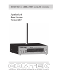
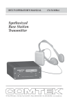
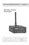
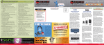
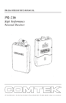
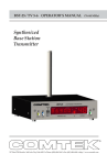
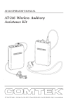
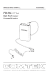
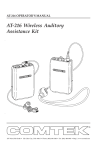
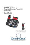
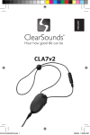
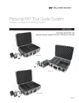
BST 25-216 OPERATOR’S MANUAL
(216 MHz)
Synthesized
Base Station
Transmitter
357 West 2700 South • Salt Lake City, Utah 84115 • Phone: (800) 496-3463 • Fax: (801) 484-6906 • http://www.comtek.com
INTRODUCTION
BST 25-216
Synthesized
Base Station
Transmitter
T
he BST 25-216 is a professional quality, auxiliary base station
transmitter designed to operate with the PR-216 and PR-216
Option 7 synthesized receivers in the 216-217 MHz band, and is
granted under FCC Parts 22, 74, and 90. This transmitter may
be used for personal cueing, for tour guide applications,
language interpretation, and for assistive listening. For
highest fidelity operation, the PR-216 receiver must be
used with the wide-band companded channels.
The BST 25-216 also operates with the Phonak microEar VHF
in-ear receiver in the narrow-band non-companded channels.
The BST 25-216 transmitter incorporates the latest digital and
analog technologies to produce low residual noise, wide
dynamic range, and extended frequency response rendering the
most natural sound possible from a wireless system.
Page 1
OPERATING INSTRUCTIONS
Equipment Placement
If the BST 25-216 base station is to be rack-mounted, a remote
antenna must be used. The base station should be mounted
away from equipment that uses large power transformers to
reduce 60 Hz hum possibilities.
If the base station is to be used outside of a traditional rackmounted environment, the screw-in whip antenna
should be free of any metallic objects when fully extended
(12 1/2 inches).
Special Note: When using the base station in close proximity
to other audio equipment,ensure that the audio equipment is
not susceptible to RF interference. This can be accomplished
by temporarily installing the base station as per above, and
then while the base station is operating, checking all audio
outputs for uncharacteristic noise. If a problem is found,
move the base station or the remote antenna as far as possible
from the affected equipment. Should you continue to have
problems, contact COMTEK’s application engineering
department for assistance.
Remote Antenna
When the base station is rack-mounted or when greater
system range is required, a remote antenna should be used.
For vehicle installation, a 1/4 wave roof-mount (MO-1/4 wave
or MAG-1/4 wave) should be used. For field or studio
applications, the COMTEK “Phase Right Antenna”
(PRA-H 216 MHz) is an easy-to-use, high performance, omni
antenna. For high gain directional yagi type antennas and
custom antennas, contact COMTEK’s application
engineering department for assistance.
Please note: Do not install screw-in whip antenna if remote
antenna is used.
Page 2
Power Requirements
The BST 25-216 base station is designed to be powered by
12 volts DC. A power adaptor is furnished for use with
standard 110V AC. The on/off switch on the front panel
of the base station turns on the transmitter.
Audio Input Connections
The base station transmitter has facilities for audio input from
a mic, line, or speaker level source. The mic/line level audio
input is a transformer balanced input and requires a standard
XLR-3 male connector. Unbalanced input is accomplished by
shorting pin-3 to pin-1 (audio ground), leaving pin-2 as the
audio source. Please note: when unbalanced input is used, it is
recommended that all audio input cables be kept as short as possible.
Set-up
a. Select an appropriate location for the base station in
accordance with “Equipment Placement” instructions.
b. Set the “MIC/LINE” switch, located on the back of the
base station transmitter, to the appropriate position: "MIC"
position for low impedance microphones or “LINE” position
for line level feed.
c. Connect the audio source or microphone to the
base station using the appropriate input. Be sure to set the
audio input level adjustment on the base station to its
full counterclockwise position.
Page 3
OPERATING INSTRUCTIONS (continued)
d. Plug the adaptor into a standard AC outlet and plug
the power connector into the DC input jack of the
transmitter. Turn the display switch on the front of the
transmitter "ON" to allow monitoring of the transmitter
frequency. Turn the main power switch on the front of the
base station to the "ON" position. The front display should
now be illuminated.
e. Mount the telescoping whip antenna in the hole on
top of the base station rotating it clockwise until it is firmly
seated. Extend the antenna completely (12 1/2 inches).
During normal operation the antenna indicator should not
flash. Turn on the transmitter and verify that the antenna
indicator is not flashing. If the antenna indicator is
flashing, it is an indication that the antenna is not fully
efficient. The antenna should be checked for appropriate
length, antenna elements in too close proximity to metallic
objects, or for a damaged coaxial cable to remote
antenna. Also, DO NOT install screw-in whip antenna if
remote antenna is used.
Audio Adjustments
In order to ensure the highest possible transmission fidelity,
the transmitter must be modulating at least 50% with
normal speech (-3 dB on the VU meter). This adjustment is
made in the following manner:
Page 4
a. Ensure that the audio source has been optimized for
best signal-to-noise ratio.
b. The “MIC/LINE” switch located at the back of the
transmitter should be switched to the appropriate setting:
"MIC" for mic level or weak line level input; “LINE” level
for line level input.
c. The “LEVEL” control on the back of the base station
should be set fully counterclockwise and then, while normal
program information is present, slowly rotate the “LEVEL”
control clockwise until the VU meter on the front panel
begins to deflect. Adjustment should be made so that
normal speech or music deflects the meter mid-scale. Only
very loud speech or music should deflect the VU meter
full-scale.
Frequency Selection
ANT
IMPORT
The BST 25-216 MHz base station transmitter can operate on
60 channels between 216 MHz and 217 MHz. Channels 1-40
are narrow-band channels for use with the Phonak microEar
receiver with 5 KHz deviation. Channels 41-60 are wideband channels for use with COMTEK PR-216 receiver with
10 KHz deviation. The PR-216 will tune the Phonak
microEar channels 1-40 but with lesser fidelity. Refer to
page 10 for Channel/Frequency Chart.
Multiple Channel Operation
Simultaneous operation of more than two channels requires
coordination of the frequencies that are used to avoid
intermodulation interference.
Page 5
OPERATING INSTRUCTIONS (continued)
To avoid this type of interference, select frequencies from one
of the standard groups (see frequency group charts on page 11), or
use COMTEK’s frequency selection guide software to determine
appropriate frequencies. (Contact COMTEK to obtain a free
copy of the frequency selection software.)
Test Tone
The BST 25-216 base station transmitter has an internal 400 Hz
source which is transmitted when the “TONE” switch is
enabled. This source is intended to be used to make technical
adjustments and to verify the operation of the system. Under
normal operation the “TONE” switch should be disabled.
Speech EQ
On the back of the transmitter there is a switch labeled “EQ”. With
this function enabled (switch up), the audio dynamics and frequency
response are processed to improve intelligibility of speech. If the
primary audio source is going to be speech, you should enable this
processing. If the main audio source is going to include music information, you should disable it. You may want to experiment to
determine which position sounds most pleasing with the program
source you intend to use.
Page 6
Display On and Off
The digital display can be turned on or off using the “DISPLAY”
switch. Disabling the display reduces the current consumption of the
transmitter for battery operation. In environments where the display
could be distracting, disabling the display may also be appropriate.
When the display is disabled, the tuning controls are also disabled,
ensuring the transmitter frequency is not changed inadvertently. With
the display disabled, one segment is turned on as a power indicator.
Additionally, the “LOCK OUT” indicator is illuminated indicating the
tuning is disabled. The VU meter and the “ANTENNA” indicator are
unaffected.
Lock Out
After the transmitting frequency has been determined, the transmitter
tuning function can be disabled with the “LOCK OUT” switch on the
back of the transmitter. This ensures that the transmitter operating
frequency is not inadvertently changed. The “LOCK OUT” indicator
(above the first numeric digit on the display) will illuminate
indicating that the tuning has been disabled. When rack-mounting
the transmitter this switch must be accessed from behind the rack.
This provides added protection from tampering.
Page 7
BST 25-216 FRONT PANEL
1
2
3
4
5 6
7
8
9
1 DISPLAY SWITCH: This switch disables the digital display to conserve
current when used with a battery.
2 TONE SWITCH: Enables/disables the internal 400 Hz test tone.
3 TUNING SWITCH: Selects the frequency on which the transmitter will
operate.
4 LOCK OUT INDICATOR: Illuminates when the “TUNING” switch is
disabled by setting the “LOCK OUT” switch (rear panel) to “ON”.
5 DIGITAL FREQUENCY DISPLAY: Displays the frequency on which the
transmitter is operating.
6 ANTENNA INDICATOR: Flashes when the transmitter senses a deficient
antenna condition.
7 VU METER: Displays the level of audio being transmitted. Used to
adjust the “LEVEL” (rear panel) control.
8 DIGITAL CHANNEL DISPLAY: Displays the channel on which the
transmitter is operating.
9 POWER SWITCH: Turns the transmitter on or off.
Page 8
BST 25-216 REAR PANEL
10
11
12
13
14
15
16
10 LOCK OUT SWITCH: Disables the front panel “TUNING” switch,
locking the transmitter on one frequency.
11 DC INPUT JACK: Requires 12 VDC at 500 mA source (Pin-1 ground,
pin-4 +12 volts).
12 EXTERNAL ANTENNA JACK: BNC connector provides a standard 50
ohm RF output for use with an external antenna.
13 SPEECH ENHANCEMENT SWITCH: Enables and disables speech
enhance feature. Enable this function (switch up) for speech, and disable
it (switch down) for music.
ANT
IMPORT
For use with Phonak’s or COMTEK IR-230, the
EQ switch should be in the “up” position.
14 LEVEL CONTROL: This control should be adjusted so that normal
audio deflects the VU meter to midscale.
15 BALANCED AUDIO INPUT: Accepts audio from a line level or dynamic
microphone (Pin-1: ground).
16 MIC/LINE SWITCH: Selects the desired audio input sensitivity.
Page 9
BST 25-216
216 MHz
FREQUENCY CHART
CHANNEL
FREQUENCY
NARROW-BAND CHANNELS
For use with COMTEK and other manufacturers
CHANNEL
FREQUENCY
32
216.7875 MHz
1
216.0125 MHz
33
216.8125 MHz
2
216.0375 MHz
34
216.8375 MHz
3
216.0625 MHz
35
216.8625 MHz
4
216.0875 MHz
36
216.8875 MHz
5
216.1125 MHz
37
216.9125 MHz
6
216.1375 MHz
38
216.9375 MHz
7
216.1625 MHz
39
216.9625 MHz
8
216.1875 MHz
40
216.9875 MHz
WIDE-BAND CHANNELS
For use with COMTEK equipment only
9
216.2125 MHz
10
216.2375 MHz
41
216.0250 MHz
11
216.2625 MHz
42
216.0750 MHz
12
216.2875 MHz
43
216.1250 MHz
13
216.3125 MHz
44
216.1750 MHz
14
216.3375 MHz
45
216.2250 MHz
15
216.3625 MHz
46
216.2750 MHz
16
216.3875 MHz
47
216.3250 MHz
17
216.4125 MHz
48
216.3750 MHz
18
216.4375 MHz
49
216.4250 MHz
21
216.5125 MHz
51
216.5250 MHz
22
216.5375 MHz
52
216.5750 MHz
23
216.5625 MHz
53
216.6250 MHz
24
216.5875 MHz
54
216.6750 MHz
25
216.6125 MHz
55
216.7250 MHz
26
216.6375 MHz
56
216.7750 MHz
27
216.6625 MHz
57
216.8250 MHz
28
216.6875 MHz
58
216.8750 MHz
29
216.7125 MHz
59
216.9250 MHz
30
216.7375 MHz
60
216.9750 MHz
31
216.7625 MHz
Page 10
BST 25-216
BST 25-216
216 MHz
NARROW-BAND
FREQUENCY GROUPS
216 MHz
WIDE-BAND
FREQUENCY GROUPS
Compatible with COMTEK
and other manufacturers
(5 kHz deviation)
For COMTEK
equipment only
(10 kHz deviation)
GROUP 1
GROUP A
CHANNEL
FREQUENCY
CHANNEL
FREQUENCY
1
9
15
24
31
36
216.0125 MHz
216.2125 MHz
216.3625 MHz
216.5875 MHz
216.7625 MHz
216.8875 MHz
41
44
51
55
60
216.0250 MHz
216.1750 MHz
216.5250 MHz
216.7250 MHz
216.9750 MHz
GROUP B
GROUP 2
CHANNEL
FREQUENCY
CHANNEL
FREQUENCY
4
10
14
32
35
40
216.0875 MHz
216.2375 MHz
216.3375 MHz
216.7875 MHz
216.8625 MHz
216.9875 MHz
42
49
53
58
216.0750 MHz
216.4250 MHz
216.6250 MHz
216.8750 MHz
GROUP C
GROUP 3
CHANNEL
FREQUENCY
CHANNEL
FREQUENCY
3
5
12
22
38
216.0625 MHz
216.1125 MHz
216.2875 MHz
216.5375 MHz
216.9375 MHz
43
46
51
57
216.1250 MHz
216.2750 MHz
216.5250 MHz
216.8250 MHz
GROUP D
GROUP 4
CHANNEL
FREQUENCY
CHANNEL
FREQUENCY
17
23
30
34
39
216.4125 MHz
216.5625 MHz
216.7375 MHz
216.8375 MHz
216.9625 MHz
44
47
54
59
216.1750 MHz
216.3250 MHz
216.6750 MHz
216.9250 MHz
Page 11
BST 25-216 INTERNAL ADJUSTMENTS
(216 MHz)
NOTE: The Compand Switch must be set to the “ON” position for automatic
companded and non-companded operation with channel selection. The “OFF”
position is only used for testing.
Page 12
BST 25-216 ACCESSORIES
Included Accessories
1. C-16 Carrying case
2. BST 25-216 Operator’s manual
3. TWA-72 Whip antenna
4. BST 25-216 Base station transmitter
5. AP-12V1 Power adaptor
(115 VAC Input)
Page 13
BST 25-216 ACCESSORIES
Optional Accessories
1. RDA-2 Remote
dipole antenna
2. PRA Phase-Right
coaxial antenna
3. MO-1/4 wave vehicle
installation antenna or
MO-1/4 wave magnetic
mount antenna
4. PRA Phase-Right
antenna mount
5. RMK 25 Single
rack-mount face plate
6. RMK 25-2 Double
rack-mount face plate
Page 14
(216 MHz)
BST 25-216 SPECIFICATIONS
Audio Inputs:
• Mic XLR, 600 ohm Balanced -40
dBV (nominal)
• Line XLR, 10 k ohm Balanced 0
dBV (nominal)
Modulation Limiter:
Soft compressor type with high
(25 dB) linear overload protection,
attack time less than 1 ms,
recovery time 10 ms
Connectors:
• XLR-3 Female audio input
connector for mic and line input
• XLR-4 Male power input 12
volts
• BNC type RF output connector
Audio Gain Control:
Greater than 40 dB
Operation Indicators:
• LED Bargraph VU Meter
displays audio input (modulation)
• Two-Digit Alpha Numeric Display
shows operating channel
• Five-Digit Numeric Display
shows operating frequency
• Antenna Indicator displays
deficient antenna condition
• Lock Out Indicator shows
tuning has been disabled
Test Tone Generator:
400 Hz 0.05% distortion
Frequency Modulation:
5 and 10 kHz deviation
RF Output Power:
Set for 100 mW
Frequency Stability:
Better than 20 ppm. digitally
synthesized, crystal controlled
Operating Frequency:
216 to 217 MHz
Harmonic and Spurious
Emissions:
Better than 55 dB below carrier
Antenna:
• Telescopic antenna mounts
directly into top of transmitter
• BNC RF output connector for
optional external antenna
Dimensions:
6 1/2" wide x 1 3/4" high x 5 5/8"
deep
FCC Compliance:
FCC Parts 22, 74, and 90
Weight:
44 oz.
Power Requirements:
12 Volts DC, 300 mA max
Frequency Response:
80 Hz to 10 kHz
NOTE: Specifications subject to change
without notice
Audio Distortion:
Less than 1% at 80% modulation
Page 15
WARRANTY AND SERVICE
Warranty
COMTEK transmitters and receivers are warranted to be free from defects in
workmanship and material under normal stand-alone use and conditions for a
period of two years from date of original purchase. Items such as headphones,
earphones, neckloops, and cords are warranted to be free from defects in
workmanship and material for a period of 90 days from the date of original
purchase. Batteries are not covered by this warranty. Damage due to abnormal
use, extreme conditions, misuse, use of the product as a component of another
product, ill treatment and unauthorized modification and repairs are not
covered by this warranty. COMTEK is not liable for any consequential or
punitive damages arising out of any failure of the equipment to perform as
intended. COMTEK shall bear no responsibility or obligation with respect to
the manner of use of any equipment sold by it. COMTEK SPECIFICALLY
DISCLAIMS AND NEGATES ANY WARRANTY OF MERCHANTABILITY
OR FITNESS OF THE PRODUCT FOR A PARTICULAR PURPOSE
INCLUDING, WITHOUT LIMITATION, ANY WARRANTY THAT THE USE
OF SUCH EQUIPMENT FOR ANY PURPOSE WILL COMPLY WITH
APPLICABLE LAWS AND REGULATIONS.
Service Policy
Warranty repairs must be done by COMTEK. Only factory technicians are
authorized to perform warranty service on the BST 25-216 transmitter. Before
returning the BST 25-216 for service, a Return Authorization Number should
be obtained from the service department by calling 1-800-496-3463 or
1-801-466-3463. Return the unit to the factory with the original or comparable
packing. COMTEK will pay for insurance and ground return shipping costs
in the United States for all warranty service.
357 West 2700 South • Salt Lake City, Utah 84115 • Phone: (800) 496-3463 • Fax: (801) 484-6906 • www.comtek.com
E-mail: [email protected]
© COMTEK® All rights reserved.
Print Release Date 02-14-2013
357 West 2700 South • Salt Lake City, Utah 84115 • Phone: (800) 496-3463 • Fax: (801) 484-6906 • http://www.comtek.com