1
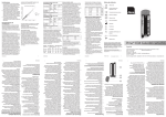
ARRAYMATE Operating Manual Version 2.1 Alere Technologies 2013 Table of Contents: 1. Introduction .............................................................................................................. 3 1.1 2. Instrument Overview ............................................................................................................................... 3 Safety Information ..................................................................................................... 4 2.1 2.2 2.3 3. Important Operation Notes ...................................................................................................................... 4 Sign description ....................................................................................................................................... 5 Technical Specifications ......................................................................................................................... 6 Installation ................................................................................................................ 7 3.1 3.2 3.3 4. Unpacking and Setup .............................................................................................................................. 7 Setup........................................................................................................................................................ 7 Start-up .................................................................................................................................................... 8 Image Recording & Analysis ....................................................................................... 10 4.1 4.2 4.3 4.4 5. Start New Test Run ............................................................................................................................... 10 Load Disposables .................................................................................................................................. 12 Image recording & analysis ................................................................................................................... 15 Shut Down ............................................................................................................................................. 16 Result data............................................................................................................... 16 5.1 6. 7. Data Export ........................................................................................................................................... 18 Errorhandling ........................................................................................................... 19 Appendix ................................................................................................................. 19 7.1 7.2 7.3 ArrayMate Interface Board ................................................................................................................... 19 Care Instruction ..................................................................................................................................... 19 Contact .................................................................................................................................................. 19 2 1. Introduction The ARRAYMATE is designed for the rapid and reliable analysis of diagnostic tests in the array platforms: ArrayTubes (AT) and ArrayStrips (AS). Two replaceable racks provided with the machine enable detection and analysis of either up to 96 ArrayStrips or 1 to 6 ArrayTube tests in one analysis run. Detection and analysis of AT or AS array images represent the final step within a multiparameter test in the array platforms. At the end of the experimental lab procedure comprising steps like sample preparation & target labelling, assay reaction on array chip (e.g. hybridisation), and precipitation staining, the ARRAYMATE reader comes into operation: the staining reaction results in a test specific colorimetric pattern generated on the array chips, which will be automatically detected and analysed by ARRAYMATE. NOTE: The optical system and therefore performance of the device is optimised for reading of ArrayStrips and ArrayTubes at dry stage, i.e. after removal of detection solution in the final assay step. Please contact us for questions on optimised assay protocols. The ArrayMate is intended to be used for research use only and not for in vitro diagnostic use. 1.1 Instrument Overview Fig.1: ARRAYMATE with monitor, keyboard, mouse and disposable racks for exchange; in the left image, the ArrayTube rack is currently in use, the ArrayStrip rack can be seen in front of the device. Designed for automated detection and analysis, ARRAYMATE is provided with a powerful integrated PC unit enabling the parallel performance of image detection and analysis. In 3 addition, the complete system comprises external TFT screen, keyboard, and mouse for comfortable user interaction. Both, ArrayTube and ArrayStrip tests can be read and analysed with the ARRAYMATE instrument. Depending on the applied platform, the appropriate rack needs to be inserted into the device enabling reading of either ArrayStrip or ArrayTubes. After opening the shutter, the trays can be easily exchanged. 2. Safety Information The ARRAYMATE is designed for application in a laboratory environment. Only trained and authorised personnel are allowed to use the ARRAYMATE. CLONDIAG is not responsible for any injury or damage caused by improper use of the ARRAYMATE reader. Please read the following safety notes carefully to avoid any misuse. Conformity ARRAYMATE complies with the requirements EN 61326-1 and EN 61326-2-6. Electrical Power The reader is licensed for an operating voltage of 100-240 V (AC), 50/60 Hz. The right environment Before starting to work with the reader, ensure that the temperature of the reader has reached room temperature in order to avoid condensation collecting within the reader. The reader needs a safe and stable standing position. Protect the reader against humidity and direct sunlight. For optimal application in combination with ArrayStrip (AS) and ArrayTube (AT) assay conditions, operate ARRAYMATE at surrounding room temperatures between 15° and 30°C (59°-86°F). Avoid any vibration during reader operation. Cleaning and Maintenance For ARRAYMATE, cleaning with a dry, soft cloth is usually sufficient. If required, the device can be additionally cleaned by using a mild detergent. In case of using a liquid detergent, disconnect power supply before cleaning. Do not clean inside the device. If you assume, that dust has collected inside the optical system, please contact the customer service. Only devices cleared with a decontamination certificate (see appendix) will be accepted for inspection and service. In case shipping of an ARRAYMATE reader for inspection and service is required, use original transportation box, only. Please contact ALERE customer service for detailed packing instructions. 2.1 Important Operation Notes Do not place any object on the shutter to avoid blocking during operation. Blocking of the automated shutter motor can lead to severe defects may result in loss of warranty rights. Do not open the reader casing. Any damage resulting from improper use will result in loss of warranty rights. For transportation, use only the original ARRAYMATE wrapping. 4 ARRAYMATE was designed for array image detection of ArrayStrips and ArrayTubes, only. Any other tubes, vials, or material must not be inserted into the reader. Performance of the optical system is optimised for reading of ArrayStrips and ArrayTubes at dry stage, i.e. after removal of detection solution in the final assay step. Apply only ArrayStrips and ArrayTubes processed with non hazardous and non corrosive reagents and solutions. The application of ArrayStrips and ArrayTubes in combination with hazardous or infectious material and reagents is in the full responsibility of the user. Avoid any contamination of the inner parts of the reader with liquids. The complete device incl. PC unit is designed and approved to run with installed ARRAYMATE software, only. Do not install any other software and do not tamper with ARRAYMATE software (this includes also general software such as Microsoft Windows, which has been specifically adapted to run with ARRAYMATE software). Any installation or manipulation of the software may lead to malfunction of the system and is in the full responsibility of the customer/user. ARRAYMATE with incl. integrated PC unit is not designed as permanent and secure data storage system. (Hard disc capacity is limited and can be reached depending on frequency of operation. No PC unit is completely secure against hardware failures like hard disk break down.) Result data output in form of hardcopies (i.e. printouts) and the performance of periodical data backups are strongly recommended. 2.2 Sign description important User manual Power on / off button on the front Read the manual Type label Serial number Type label Manufacture date Type label Manufacturer Type label Read this manual Type label European Conformity Type label 5 2.3 Technical Specifications Components detection unit, pixel resolution CMOS-camera, 1280 x 1024 (5.2µm/pixel) camera interface USB 2.0 data matrix reader 2 units for disposable rack identification light source diode array PC unit: - main board - processor - disk space - RAM - operating system - external interfaces - Kontron 986LCD-M/mITX Intel® Core™2 Duo, 2,16GHz T7400 min. 160 GB 3 GB DDR2-RAM MS Windows XP SP 3 RS232 C, lSUB-D 9-pole VGA PS/2 mouse, PS/2 keyboard USB 2.0 (4x) - IEEE1394 10/100/1000 Bbps Ethernet Controller HD Audio & AC97 compliant - optional external interfaces Environmental operating temperature 15°C-30°C (59°-86°F) storage temperature -10°C-55°C relative humidity no relative humidity leading to condensation within device sunlight no direct sunlight method of disposal disposal by customer: follow guidelines related to electronic devices for medical products. ALERE accepts devices for disposal, which have been sent back on the customer's expense with a signed decontamination certificate (see certificate at the end of this document). Physical dimensions (width x depth x height) 354 x 360.5 x 208 mm (reader only) weight 13 kg (reader) 5.6 kg (monitor) Power supply 100-240 V (AC), 50/60 Hz consumption 50 W (typ.) protection system overcurrent/overload/short circuit protection 6 3. Installation 3.1 Unpacking and Setup To unpack the ARRAYMATE device, the transportation box needs to be in an upright position to open. ARRAYMATE needs at least 600 x 700 x 600 mm (w x d x h) space and a safe and stable standing position at bench level. Carefully lift and place the ARRAYMATE in position. (Heavy weight of approx. 13 kg!) Inspect for any obvious sign of damage and report any damage immediately to CLONDIAG customer service. Ensure free ventilation of the instrument. Both ventilation slots on back and right instrument side must not be covered and require sufficient free space for air circulation. Unpack ARRAYMATE equipment and TFT packed in a separate box. Inspect for any obvious sign of damage and report any damage immediately to CLONDIAG customer service. Before any further installation of instrument and equipment, ensure that the temperature has reached room temperature in order to avoid condensation collecting within the device. Remove protection belt. 3.2 Setup Main power connector and POWER ON switch are situated on the back left side of the instrument. Place the device in such a way that you reach the switch in the back of the device any time. All other connectors and external interfaces are placed on the right rear side of the instrument, as displayed in fig. 2 and fig. 3. (For details on the interface connector board, please refer to Appendix 6.2) Main POWER switch & power supply cable inserted in appropriate line connector fig. 2: back side of ARRAYMATE with POWER ON switch and type plate with serial number Connect provided power supply cable with the instrument's line connector on the back side of the device and plug it into a power socket. WARNING! The instrument must be only connected to power sockets with operating voltage written on type label! 7 Place TFT screen on top of the device (as shown in fig. 3) or alternatively besides ARRAYMATE. Plug provided TFT power supply cable into appropriate power connector and VGA cable into VGA connector of connector board at the right side of ARRAYMATE. Place mouse and keyboard in front of the device and plug into related PS2 and USB connectors of connector board on the right side of the instrument. fig. 3: right side with connector board for monitor, PS/2, serial, USB and other interfaces 3.3 Start-up For inserting either ArrayStrip or ArrayTube disposable rack, the ARRAYMATE needs to be turned on. (Only then the shutter can be opened and a rack can be inserted.) Turn on the device by pressing at first the main power switch on the back side (see fig. 2) and then the power ON button on the front side of ARRAYMATE. Power ON status will be indicated by the blue LED right beside the power on button (see fig. 4). fig. 4: System Power ON button and status LEDs: blue LED indicating ON status of the system yellow LED indicating instrument error 8 Now turn on TFT screen by entering the related power button. NOTE! When starting TFT for the first time, apply monitor button 'Auto adjust' for one time for proper adjustment of the monitor screen. The login screen will appear: fig. 5: login screen The admin login (password protection) should be enabled for advanced ARRAYMATE service and data management operation, only. For standard user operation, login the user mode. This mode enables all standard reader operation like reading, analysis, and archive data editing. The User R&D mode (password protection) is an extension. It shows more information than the user mode. NOTE! After login, ARRAYMATE software will upload and an automated device initialisation procedure will start, which may last a few minutes. fig. 6: initialisation screen with version number 9 4. Image Recording & Analysis After successful initialisation procedure, the start screen as displayed in fig. 7 appears. The device is now ready for a new test run or for editing data of recorded and analysed tests within the ARRAYMATE Archive. “New Run” “Archive” “Power” Button fig. 7: start screen of ARRAYMATE software 4.1 Start New Test Run Select button "New Run" in the upper left corner of the start screen, fell out “Run infos” and chooses one detection mode in “Experiment infos”. The reference name is required for the correct management of each ARRAYMATE test run and its storage within ARRAYMATE Archive. NOTE! One run consists of either 1-96 single tests in case of applying the ArrayStrip rack filled with 1-12 ArrayStrips or of 1-6 single tests in case of applying the ArrayTube rack filled with 1-6 ArrayTubes. fig. 8: Start Screen “New Run” 10 Experiment Infos User Automatic detection - User R&D During operation, ARRAYMATE will automatically recognise the inserted rack and therefore the type of disposables to be analysed in the current run. Both disposable racks are provided with an unique data matrix code enabling correct identification. (see fig. 9) User User R&D Worklist ArrayStrips Worklist ArrayTubes Manual settings for ArrayStrips Manual settings for ArrayTubes In case individual test identification and specification is preset by an external lab software or LIMS, test number and type can be imported in this mode. If you want to write a worklist by yourself, you can find a description in the kit manual. - - This mode is only required, if reading of the rack data matrix code fails. This can occur in case of scratches or impurities on the data matrix code of the racks. Avoid accidental contaminations or scratches, which may obliterate the code. If disposable type identification frequently fails, please inform CLONDIAG customer service. 11 fig. 9: ArrayTube rack labelled with data matrix code for rack identification 4.2 Load Disposables Now press "Next" button on the lower right corner of the window. A screen appears asking to insert the disposables to be analysed. At the same time, the shutter of the ARRAYMATE is opening: fig. 10: ARRAYMATE with open shutter and rack fitting ready for inserting either ArrayStrip or ArrayTube rack Insert ArrayStrips For ArrayStrip test runs, insert at first the required amount of strips into ArrayStrip rack outside of device and only then position complete rack into rack fitting (see fig. 11a): Slightly press ArrayStrips into rack to ensure proper hold. Now position rack with inserted ArrayStrips into rack fitting by placing the two rack wholes onto the metallic guide pins of the rack fitting. NOTE! In case "automatic detection" mode was selected in the field for "Experiment infos", the ArrayStrip rack can be loaded individually. e.g. empty rows between two strips are possible. However in case the “Manual settings for ArrayTubes” mode was selected, rack loading needs to be started with inserting first ArrayStrip into row 1, second ArrayStrip into row 2, etc. No empty row between two strips is allowed (see fig. 11b). 12 rack wholes fig. 11a: ArrayStrip rack with inserted strips and rack wholes for position rack into rack fitting. Ensure correct insertion of strips by slightly pressing them into strip frame. In case of "automatic detection" mode, empty rows between strips are possible. fig. 11b: if manual input of number of tests was selected, rack loading needs to be performed in series starting with row 1 without empty rows in between. Insert ArrayTubes For ArrayTube test runs, position at first ArrayTube rack into rack fitting by placing rack wholes onto metallic guide pins (see fig. 11a) and insert then single tubes into the rack. Ensure, that tubes and tube lids are properly inserted as demonstrated in fig. 12. fig. 12b: incorrectly placed ArrayTubes fig. 12a: ArrayTubes correctly inserted into ArrayTube rack: ArrayTubes need to be open with tube-lid connections placed into appropriate notches. When rack incl. disposables were successfully inserted, press "Next" button on the lower right corner of the screen. Shutter will close, and the device starts data matrix code scanning to identify at first the selected disposable type and then number and assay of applied disposables. Depending on the number of inserted disposables, this process may last several seconds, especially in the ArrayStrip reading mode. 13 Proceeding of the scanning process is visualised on the screen: fig. 13: progress screen displaying status of number and type of identified ArrayStrips. During identification scanning, data matrix code of each applied ArrayStrips will be read and analysed. Identified ArrayStrips with related assay type will be marked with the appropriate assay ID. In the example, ArrayStrips have been detected in rows 2, 4, 5, 6, 7, and 8, i.e. 6 ArrayStrips are to be analysed. NOTE! Data matrix code of each disposable includes the specific assay ID, which determines procedure of the subsequent analysis. If a code cannot be read and analysed, e.g. due to an assay ID not known by the system, the test run will be aborted. Please see also appendix A for specification of disposable data matrix code. 14 4.3 Image recording & analysis Immediately after disposable identification scanning, reading of the ArrayStrip or ArrayTube arrays is starting. Subsequent analysis of the recorded images will be automatically initiated and performed already during the imaging process. Proceeding of the analysis process is visualised on the screen: fig. 14: ArrayStrip image recording starts with most-right strip (here strip in row 12) and continues subsequently up- and downward to the left side. Image calculate protocol NOTE! In case of ArrayTube analysis, identification scanning and image recording are performed in series for each ArrayTube: i.e. first ArrayTube position will be approached for identification scanning and subsequent image recording, then second one etc. In case of ArrayStrip analysis, at first all strip positions starting with row 1 are approached for identification scanning, and only afterwards array image detection starts (figs. 13 and 14). This difference in reading progression is due to the geometrical arrangement of the individual camera systems for both data matrix scanning and array imaging. When array image reading is finished, the message "Remove disposables" appears and the shutter will open. Remove disposables. 15 Now a new test run can be initiated or the recorded and analysed image data can be viewed ad edited in the Archive mode. 4.4 Shut Down To shut down user software and ARRAYMATE instrument, click on "Power" button in lower left corner of ARRAYMATE start screen. In case, that the door is still open after shut down, please start the device again. It will be closing while initialise. Then you can shut down the device again. 5. Result data For viewing and editing result data and images, enter Archive mode. Select button "Archive" in the upper left corner of the start screen. A directory with all test runs is listed in the left tree window: fig. 13: Enter "Archive" mode for viewing, editing and searching result data. In the left tree window signed by the flag "Browse", a list of all ArrayStrip and ArrayTube test runs is displayed. By clicking on one specific test run, all single tests comprising to one run will be listed in the right window (results, results b, raw data, segmentation image, test related array image, can be viewed by selecting the individual flag). 16 fig. 14: results of one test The flag “result” is designed for summarised and interpreted result presentations. Depending on the assay type, these presentations can consist of bar graph summaries, result tables with diagnostic interpretation etc. They usually can be setup only after assay validation and threshold determination and need to be programmed customised. For further information, please contact us. The flag “results b” is an extension of “results”, which includes more information. Presented “raw data”1 depend on the individual IconoClust analysis script and can be adapted customised. The “segmentation image”1 is generated only after successful image analysis by IconoClust software representing successful grid and spot recognition. The “image”1 is needed to analyse the test run. 1 ) Only shown in User R&D mode. 17 5.1 Data Export Result data export can be performed directly out of the ARRAYMATE Archive mode or out of the Windows mode, which can be started within Administrator mode. NOTE: Only authorised Users are able to export data out of the Archive mode. Authorised Users of the ARRAYMATE are to be determined by the Administrator via Windows User roles. Export within User mode Enter Archive mode and select run to be exported by right mouse click. In the popup, you can select "Export Run". A new window opens enabling to enter a different name for the selected run. Type in individual name and press 'ok'. A popup asking for entering the directory, where the exported data are to be stored, opens up. Enter new directory and press 'ok'. Test run including all individual tests will be renamed and stored at the selected directory. Export within User R&D mode Enter Archive mode and select run to be exported by right mouse click. In the popup, you can select "Export Run", "Export Run Reports", "Edit Run", "Delete Run". In case you want to rename the individual test run, select "Edit Run". A new window opens enabling to enter a different name for the selected run. Type in individual name and press 'ok'. A popup asking for entering the directory, where the exported data are to be stored, opens up. Enter new directory and press 'ok'. Test run including all individual tests will be renamed and stored at the selected directory. Export within Administrator mode ARRAYMATE needs to be started in the Administrator mode. Type in Administrator password to enter Windows and then Windows explorer. All data files generated by ARRAYMATE test runs are stored within the directory D:\archive_root\'name of test run'. Data export can be performed via one of the USB- or the LAN interface accessible right rear side of the instrument (see fig. 3). 18 6. Errorhandling Device doesn’t start switch off the device (backside switch), wait some seconds and switch on again switch off the device (backside switch), close the door with hands (do this only without power on the device!), switch on and restart normally Contact Alere Technologies GmbH Door doesn’t close correctly Blue led don’t stop blinking after switch on If you send back the device to repair, please fill out the formular “Decontamination Certificate” on the end of this manual and send it to us. 7. Appendix 7.1 ArrayMate Interface Board ARRAYMATE is provided with an extended interface and connector board on the right rear side (see also fig. 3 on page 8). a b c d e c a e d RS232 C (unused) PS/2 keyboard PS/2 mouse (unused) VGA (monitor) USB 2.0 (4x) 1x USB mouse, 3x free b fig. 15: plug-in 7.2 Care Instruction Clean with water or with mild detergent only. Do not use aggressive chemicals like hypochlorite, H2O2 etc. Avoid disinfection. If disinfection is necessary use alcohol-based disinfectants. Do not expose to disinfectant for a longer period of time than necessary for disinfection and rinse with pure water thereafter. 7.3 Contact Alere Technologies GmbH Löbstedter Str. 103 - 105 D - 07749 Jena Phone: +49-36 41-3111 0 Fax: +49-36 41-3111 120 www.alere-technologies.com 19 Decontamination Certificate Institute Name & Address ______________________________________ ______________________________________ Instrument Serial No. ______________________________________ ______________________________________ This instrument has not been in contact with blood, other body fluids, or any infectious sample material. It has not been used in an invasive procedure. The instrument has been cleaned and decontaminated in preparation for inspection, service, or repair. The decontamination procedure is as outlined below: ______________________________________________________ ______________________________________________________ The instrument could not be contaminated. The natures of risk and safety precautions to be adopted are as follows: ______________________________________________________ ______________________________________________________ ______________________________________________________ Signed:_____________________________ Date:____________________ Position:_____________________________________________________ Address:_____________________________________________________ Tel.No.:______________________________________________________ 20