1
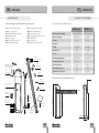
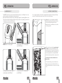
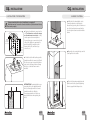
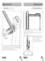
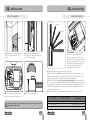
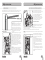
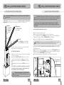
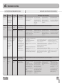
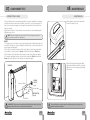
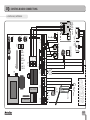
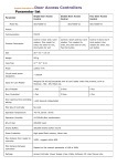
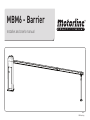
MBM6 - Barrier
Installer and User’s manual
v2.0
REV. 11/2013
00. CONTENT
01. SAFETY INSTRUCTIONS
▷ INDEX
STANDARDS TO FOLLOW ◁
00. CONTENT
▷ index | pág 01.A
ATTENTION:
▷ To ensure the safety of people, it is important that you read all the following
instructions.Incorrect installation or incorrect use of the product can cause physical
injury and material damage.
▷ Keep these instructions in a safe place for future reference.
▷ This product was designed and produced strictly for the use indicated in this
manual. Any other use, not expressly indicated here, could compromise the good
condition/operation of the product and/or be a source of danger.
▷ ELECTROCELOS SA is not responsible for the improper use of the product,
or other use than that for which it was designed.
▷ ELECTROCELOS SA is not responsible if safety standards were not taken
into account when installing the equipment, or for any deformation that may occur to
it.
▷ ELECTROCELOS SA is not responsible for the safety and proper operation
when using components not sold by them.
▷ Do not make any modifications to the operator components and / or their
accessories.
▷ Beffore installation unplug the automatism from the source of power.
▷ The installer must inform the client how to handle the product in case of
emergency and provide this manual to user.
▷ Keep remote controls away from children, to prevent the automated
system from being activated involuntarily.
▷ The customer shall not, under any circumstances, attempt to repair or tune
the operator .Must call qualified technician only.
▷ Connect the automatism to a 230V plug with ground wire.
▷ Operator for outdoor and indoor use.
01. SAFETY INSTRUCTIONS
▷ standards to follow | pág 01.B
02. PACKAGE
▷ inside package | pág 02.A
03. OPERATOR
▷ technical specifications | pág 02.B
▷ warning light | pág 03.A
▷ locking / unlockin | pág 03.B
04. INSTALATION
▷ installation site preparation | pág 04.A
▷ barrier’s fixation | pág 04.B
▷ boom assembly | pág 05.A
▷ boom support installation | pág 05.B
▷ top cover removal | pág 06.A
▷ spring adjustment | pág 06.B
▷ boom leveling | pág 07.A
▷ limit-switch and stoppers adjustment | pág 07.B
05. CONTROL BOARD MC15 CONFIGURATION
▷ checking limit-switches connections | pág 08.A
▷ barrier’s course configuration | pág 08.B
▷ transmitters configuration | pág 09.A
▷ pause time configuration | pág 09.A
▷ Condominum function and potenciometers | pág 09.B
06. TROUBLESHOOTING
▷ final consumers instructions | pág 10.A
▷ specialized technicians intructions | pág 10.A
07. COMPONENTS TEST
▷ connections scheme | pág 11.A
08. MAINTENANCE
▷ maintenance | pág 11.B
09. CONTROL BOARD CONNECTIONS
▷ MOTORLINE MC15 control board | pág 12.A
01.A
01.B
02. PACKAGE
03. OPERATOR
▷ INSIDE PACKAGE
TECHNICAL SPECIFICATIONS ◁
Inside the package you will find the following components:
▷ 01 electromechanical barrier
▷ 01 MC15 control board
▷ 02 4channel MX4SP transmitter
▷ 01 aluminium boom
▷ 01 boom support
▷ 01 MF1 exterir photocells set
▷ 02 fastening metal plates
The specifications of the MBM6 barrier are:
▷ 01 boom fastening metal plate
▷ 04 M16 bolts with bushings
▷ 04 boom fastening screws
▷ 02 boom support fastening screws
▷ 01 RGB LED board
▷ 01 cover for boom
▷ 01 installer and user’s manual
MBM6 230 v
MBM6 24 v
AC 230V 50/60Hz
AC 230V 50/60Hz
AC 230V
24v DC
90W
80W
?
?
2800RPM
1400 RPM
<65dB
<65dB
x
x
-45°C a 65°C
-45°C a 65°C
▷ Thermal protection
120°C
-
▷ Protection level
IP55
IP55
▷ Working frequency
80%
Intenso
▷Opening / Closing time
3-6s
3-6s
▷ Barrier’s Power Supply
▷ Motor’s Voltage
▷ Power
▷ Current
▷ RPM
▷ Noise level
▷ Force
Boom
fastening screws
▷ Working temperature
Boom
metal plate
RGB LED board
MC15
control board
Boom
cover
MX4SP
transmitter
Electromechanical
barrier
The main dimensions of the MBM6 barrier are:
53 mm
MF1
photocells
M16 screws
with bushings
Installer and
user’s manual
Boom
support
840 mm
Boom
support
fastening
screws
1170 mm
100 mm
Fastening
metal plates
Aluminum
boom
214 mm
321 mm
02.A
296 mm
02.B
03. OPERATOR
03. OPERATOR
▷ WARNING LIGHT
LOCKING / UNLOCKING ◁
The MBM6 barrier is a product developed with the purpose of controlling the access of
vehicles to private, industrial and commercial areas.
One of the main functionalities is the warning light capable of emitting different colors.
This was developed to identify the different stages of the boom (opening, openned and
closing) in a more clear and visible way.
DETAIL: Barrier’s warning light
During opening course - warning light
emits GREEN light
In case of power failure, the barrier is equipped with a manual unlocking and locking
system. Follow the bellow instructions to unlock or lock the barrier.
1▷ Open the door using the key supplied
with the barrier. Rotate the key to unlock
the door and pull it towards outside.
On the interior, you will have access to the
unlocking system.
2▷ The unlocking is made by pressing and
rotating the motor wheel shaded on the
image on the side. The rotation direction to
unlock will depend on the current stage of
the boom (openned or closed) which will
make the rotation possible to only one side.
You must rotate the red wheel to the
easiest side.
To lock the barrier, you must do the same
steps because once it is unlocked, the red
wheel will only be able to rotate to one of the
sides.
During pausing time while openned warning light emits BLUE light
During closing course - warning light
emits RED light
03.A
03.B
04. INSTALLATION
04. INSTALLATION
▷ INSTALLATION SITE PREPARATION
BARRIER’S FIXATION ◁
It’s important that this order of installation is respected!
Otherwise we can’t assure the correct installation of the barrier and it may
not work properly.
m
36
0m
26
0m
m
20mm
(height of
foundation
above soil)
500 mm
(total
height of
foundation)
45
a1
20
m
m
0mm
110 a 18
1▷ Create a foundation in cement on the
soil. The dimensions on the side image
are the minimum to maintain, so they
can be superiors but never inferiors.
You must leave one or more tubes for the
cables of the different components to
pass through the foundation to the
barrier (photocells, wall starts, key
selectors, etc)..
3▷ With the bolts already fixed on the
cement foundation, respecting the
dimensions of point 2, place the barrier on
top of the foundation in a way that the
screws stay inside and centered with the
barrier.
4▷ Open the door using the key to unlock
it, and pull it to the outside.
2▷ Solder the bolts with bushings on the
foundation while the cement is still fresh.
It is also necessary to respect the dimensions on the side image when soldering
the bolts, so that the barrier can be
installed.
ALTERNATIVE▷ During installation, you
can replace the bolts supplied by metal
hooks, soldering them on the cement
foundation while it is still fresh.
You must pay attention to the above
image’s dimensions when placing the
hooks.
04.A
5▷ Place the fastening metal plates and
fix the barrier to the ground tightening
the nuts supplied with the product.
04.B
04. INSTALLATION
04. INSTALLATION
▷ BOOM ASSEMBLY
BOOM SUPPORT INSTALLATION ◁
After assembling the boom, you must define the length of it so that you can fix the
boom support, as visible on the image above.
When the boom’s length is decided, fix it with the two small screws situated at the end
of the fix part of the boom.
When the position of the boom’s support
is defined, you can fix it to the ground.
Make two holes on the fixing ground, and
place the screws supplied.
Align the support holes with those same
screws and fasten the support using the
nuts.
To assemble the boom, you must place the boom on the barrier fixing plate and align
the four holes on each piece. The you just need to place the boom fastening metal plate
and use the screws to fasten the three parts together.
When the boom is fixed, use the cover to hide these fastening parts.
05.A
05.B
04. INSTALLATION
04. INSTALLATION
▷ TOP COVER REMOVAL
SPRING ADJUSTMENT ◁
phase 5
phase 4
phase 3
phase 2
1▷ Open the door using the key supplied
to unlock it and then pull it to the
outside.
phase 1
2▷ Rotate the rod (image above) to
unlock the cover. There are two rods, one
on each side of the barrier.
ADJUSTMENT▷ To adjust the springs,
you must use a wrench to fasten or
release the springs nuts. If you rotate
them clockwise you are giving tension to
the springs causing the boom to rise up,
and rotating counterclockwise you are
removing tension from the springs
causing the boom to descend.
1▷ Unlock the barrier (please follow steps on page 03.B)
2▷ Put the boom like on phase 1 as shown on the above image. Let it go and it must
maintain on that position, or rising very slowly. If the boom starts to descend or rise
adjust the springs untill you can make the boom become stabilized.
3▷ Put the boom like on phase 2, phase 3, phase 4 and phase 5 and repeat the same
process of point 2 for each phase. With the adjustment of the springs, you must achieve
a stage where you can let go the boom in each position you desire and it must stay
stabilized. The springs must be calibrated to sustain the total wheight of the boom
without the help of the motor.
4▷ When the springs are tuned, lock the barrier follwoing the steps on page 03.B.
3▷ The hooks that secure the top cover
are also rotated and release the cover.
4▷ Pull the cover up to remove it.
When assembling the top cover on the barrier, you must do the exact same
steps but in reverse order.
06.A
Boom Length
Number of Springs
Spring’s Length and
Steel Diameter
<3600mm
1
440mm (1 spring of Ø5mm)
3600 - 5000mm
1
440mm (1 spring of Ø6mm)
5000 - 6000mm
2
440mm (1x Ø5mm + 1x Ø6mm)
06.B
04. INSTALLATION
04. INSTALLATION
▷ BOOM LEVELING
LIMIT-SWITCHES AND STOPPERS ADJUSTMENT ◁
After installing the barrier, you must verify the position of the boom while closed. If it
isn’t aligned horizontaly when closed, follow the instructions bellow to adjust it.
(Horizontal level)
The mechanical limit-switches of the
barrier are shown on the image on the left.
They consist of two rings fixed to the
boom’s rotation shaft, that when openning or closing will activate the
micro-switches also installed. This will
cause the control board to stop the barrier
when the micro-switches are activated,
one for each type of maneuvers.
Adjust limit-switches:
IMPORTANT: You must turn off the power
supply so there is no risk to activate the
barrier acidentally and cause an accident.
Barrier’s interior:
1▷ Loosen the nuts of the extensible arm
shown in the image of the barrier’s interior.
2▷ Insert a small rod on the hole located on
the extensible arm so you can rotate it
more easily.
3▷ To level the boom when closed, you just
need to rotate the extensible arm. If you
rotate to the direction shown by the arrow
of the image, you are reducing it’s size and
causing the boom to rise. If you rotate on
the other direction, you are increasing it’s
size causing the boom to descend.
4▷ When the boom is leveled, you must
fasten the nuts of the extensible arm to
lock it’s length. This will prevent the arm to
accidentally increase or decrease during the
normal usage of the barrier.
NOTE▷ The development of all mechanical
parts was made to assure an opening
degree of 90° in whatever leveling position
you adjust the boom. This means that if you
align it horizontally when closed, it will be
vertically aligned when openned.
07.A
1▷ Slightly loosen the screw of the ring you
want to adjust, so it becomes easier to
move.
2▷ Rotate it to the desired position, so it can ativate the micro-switch and stop the
boom on the correct position.
3▷ Fasten the screw of the ring you’ve adjusted to fis it on that position.
NOTE: When adjusting the limit-switches you must also need to adjust the mechanical
stoppers.
The mechanical stoppers shown in the
image on the side, were developed to limit
the movement of the arms inside the
barrier’s body.
After adjusting the limit-switches, you
must need to adjust the stoppers so that
the arm shaded on the image touches
them as soon as the micro-switches are
activated.
This will cause the stoopers to hold the
boom’s wheight when it gets to end of
course.
To make the adjustments, you just need to
loosen the bolts that fix them, rotate them
and fasten the bolts to fix them on that
position.
07.B
05. MC15 CONTROL BOARD CONFIG
05. MC15 CONTROL BOARD CONFIG
▷ CHECKING LIMIT-SWITCHES CONNECTIONS
BARRIER’S COURSE CONFIGURATION ◁
To program the MBM6 24V you must consult the manual of the MC41SP
control board.
The first step to program the control board is to verify all connections of the various
components. Please verify the scheme of the connections on the page 12.A
Openned:
- the LED FAP must
switch OFF and
the LED FCH
must keep
ON.
Middle course:
- the LEDs FAP e FCH
must keep ON.
The LEDs BL e DS must be both ON so that the barrier can work properly.
If they are not, check the connections of the security devices. In case you
don’t use any security device, please close all circuits with shunts.
You must start the configuration with both potenciometers at middle
adjustment. The final adjustment will be made after programming the barrier’s course.
▶ Programming the barrier’s course:
Closed:
- the LED FCH must switch OFF
and the LED FAP must keep ON.
After you check the connections, you must check if the
limit-switches are working properly.
▶ Check limit-switches:
1▷ Unlock the barrier (see page 03.B) and move it manually
to middle course (45º).
2▷ Verify if the LEDs FCH e FAP are ON. If not, check the
connections. When both LEDs are ON, go to next step.
3▷ Manually close the barrier and LED FCH must switch
OFF.
4▷ Manually open the barrier and LED FAP must switch
OFF.
If the LEDs don’t switch OFF as explained it means that
their cables are badly connected. Switch the cables of
the terminals 7 and 9 of CN3 connector.
1▷ Unlock the barrier (see page 03.B).
2▷ Place the boom manually at middle course and lock the barrier.
3▷ Press the SEL key and the LED CODE will start to blink. Press again the SEL key as
many times as you need untill the LED PGM AUTO starts blinking.
4▷ Press and hold SET key and the boom must start to close!
WARNING: If the boom starts opening, release the SET key, switch the cables of
the terminals 5 and 7 of CN2 connector and restart this programming.
5▷ Let the barrier close, open and close once again automatically, always keeping
the SET key pressed.
6▷ Once the barrier finishes closing for the second time, the LED PGM AUTO will stay
ON permanently and the LED T.MOTOR will start to blink. Release SET ket and wait
10seconds untill the LED T.MOTOR stops from blinking.
7▷ The programming is now complete and you can use the barrier normally.
PGM AUTO
SET
SEL
All the programming process must be made
with the control board connected to a 230V
power supply.
08.A
08.B
05. MC15 CONTROL BOARD CONFIG
05. MC15 CONTROL BOARD CONFIG
▷ TRANSMITTERS CONFIGURATION
CONDOMINIUM FUNCTION AND POTENCIOMETERS ◁
Once you have the barrier’s course configured, you can now program the transmitters:
▶ Programming transmitters:
1▷ Press one time the SEL key and the LED CODE will start blinking.
2▷ Press one time the transmitter key that you desire to operate the barrier.
3▷ When pressing the transmitter key, the LED CODE must turn and stay ON signaling
the sucess of the configuration.
If the LED CODE doesn’t stay ON, the transmitter was not programmed. Please
repeat the same steps to try once again.
NOTE: To program several transmitters, repeat the same steps above for each one of
the transmitters.
▶ Activate e deactivate condominium function:
1▷ Press the SEL key and the LED CODE will start blinking. Press again the SET key as
many times as you need until the LED CMD AP starts blinking.
2▷ Press SET to confirm.
3▷ If the LED CMD AP stays ON it means that the function is activated, and if it stays
OFF it means that the function is deactivated.
▶ Adjust sensibility and force potentiometers:
▷ PAUSE TIME CONFIGURATION
The force potentiometer controls the force of the motor when opening and closing.
The sensibility potentiometer controls the sensibility of the control board when
detecting obstacles. The more sensitive it is the quicker it will detect any obstacle
during it’s course and invert the orientation of working of the motor.
The pause time is the time that the barriers stays paused since it completes the
opening maneuver untill it starts to close automatically.
▶ Programming the pause time in automatic mode:
1▷ Press the SEL key one time and the LED CODE will start blinking. Press again the SET
key as many times as you need until the LED T.PAUSA starts blinking.
2▷ Press SET one time and wait as much time as you want for pause time.
3▷ Press SET one time and the pause time is defined.
T.PAUSA
The condominium function of this control board causes the barrier to only accept
opening orders. When the barrier is closed, if you press the transmitter’s key to open, it
will start openning, but during the openning maneuver or when it is already openned, if
you try to close it, the control board won’t accept it.
This causes the barrier to only close automatically.
CODE
1▷ To adjust the potentiometers, you just need to rotate them with a small screwdriver.
Rotating to the right you will increase the values and to the left, you will reduce it.
NOTE: Everytime you make an adjustment to the force potentiometer, you must
perform a new barrier’s course programmation (see page 08.B).
SET
CMD AP
SEL
Sensibility
Force
09.A
09.B
06. TROUBLESHOOTING
▷ INSTRUÇÕES PARA CONSUMIDORES FINAIS
Anomaly
Procedure
Behavior
INSTRUÇÕES PARA TÉCNICOS ESPECIALIZADOS ◁
Procedure II
Discovering the origin of the problem
▷ Barrier
doesn't work
▷ Make sure you
have 230V power
supply connected to
operator and if it is
working properly.
▷ Still not
working
▷ Consult a qualified
MOTORLINE technician.
1 ▷ Open control box and check if
it has 230V power supply;
2 ▷ Check input fuses;
▷ Barrier
doesn’t move
but makes
noise
▷ Unlock barrier and
move boom by hand
to check for
mechanical problems
on the movement
▷ Encountered
problems?
▷ Consult a qualified
MOTORLINE technician.
1 ▷ Check all motion axis and associated motion systems related with the barrier to find out what is the problem.
▷ Boom moves
easily?
▷ Consult a qualified
MOTORLINE technician.
1 ▷ Check capacitors, testing
operator with new capacitors;
2 ▷ If capacitors are not the
problem, disconnect motor from
control board and it them by
▷ Barrier
opens but
doesn’t close
▷ Unlock motor and
move boom by hand
to closed position.
Lock motor again and
turn off power supply
for 5 seconds.
Reconnect it and
send order to open
barrier using
transmitter.
▷ Barrier
opened but
didn’t close
again
1 ▷ Check if there is any
obstacle in front of the
photocells;
2 ▷ Check if any of the
control devices (key
selector, push button, video
intercom, etc.) of the gate
are jammed and sending
permanent signal to
control unit;
3 ▷ Consult a qualified
MOTORLINE technician.
All MOTORLINE control boards have LEDs
that easily allow to conclude which devices
are with anomalies.
All safety devices LEDs (DS) in normal
situations remain On.
All "START" circuits LEDs in normal situations
remain Off.
▷ Unlock barrier and
move boom by hand
to check for
mechanical
problems on the
barrier.
▷ Encountered
problems?
▷ Consult a qualified
MOTORLINE technician.
1 ▷ Check all motion axis and associated motion systems related with the barrier to find out what is the problem.
▷ Boom moves
easily?
▷ Consult a qualified
MOTORLINE technician.
1 ▷ Check capacitors, testing with
new capacitors;
2 ▷ If capacitors are not the
problem, disconnect motor from
control board and test it by
connecting directly to power
supply in order to find out if it is
broken;
3 ▷ If the motor doesn’t work,
remove it from installation site
and send to our MOTORLINE
▷ Barrier
doesn’t make
complete
route
3 ▷ Disconnect barrier from
control board and test them by
connecting directly to power
supply in order to find out if they
have problems
(see page 11.A).
4 ▷ If the barrier works, the
problem is on the control board.
Pull it out and send it to our
MOTORLINE technical services
for diagnosis;
3 ▷ If the motor works, the
connecting directly to power
supply in order to find out if it has problem is from control board.
problems (see page 11.A).
Pull it out and send it to our
MOTORLINE technical services
for diagnosis;
If LEDs devices are not all On, there is some
security systems malfunction (photocells,
safety edges), etc.
If "START" circuits LEDs are turn On, there is
a control device sending permanent signal.
5▷ If the barrier doesn’t work,
remove them from installation
site and send to our MOTORLINE
technical services for diagnosis.
4 ▷ If the motor doesn’t work,
remove them from installation
site and send to our MOTORLINE
technical services for diagnosis.
A) SECURITY SYSTEMS:
B) START SYSTEMS:
1 ▷ Close with a shunt all safety systems on
the control board (check manual of the
control board in question).
If the automated system starts working
normally check for the problematic device.
2 ▷ Remove one shunt at a time until you
find the malfunction device .
3 ▷ Replace it for a functional device and
check if the operator works correctly with
all the other devices. If you find another one
defective, follow the same steps until you
find all the problems.
1 ▷ Disconnect all wires from START terminal
input (terminal 3 of CN3 connector).
2 ▷ If the LED turned Off, try reconnecting
one device at a time until you find the
defective device.
technical services for diagnosis.
4 ▷ If motor work well and move
gate at full force during the
entire course, the problem is
from controller. Set force using
trimmer on the board. Make a
new working time programming
, giving suffient time for opening
and closing with appropriate
force (page 08.B of this manual
for MBM6 230V).
NOTE:
In case procedures described in sections A)
and B) don’t result, remove control board
and send to our technical services for
diagnosis.
5 ▷ If this doesn’t work, remove
control unit and send it to
MOTORLINE technical services
services.
NOTE: Setting force of the
controller should be sufficient to
make the barrier open and close
without stopping, but should
stop and invert with a little effort
from a person.
In case of safety systems failure,
the barrier shall never cause
physical damaged to obstacles
(vehicles, people, etc.).
10.A
07. COMPONENT TEST
08. MAINTENANCE
▷ CONNECTIONS SCHEME
MAINTENANCE ◁
To detect which are the components with problems in barrier’s installation, sometimes
it will be needed to run some tests with direct connection to a 230V power supply. For
that, it’s necessary to interpolate a 10µF capacitor in between the connection for the
barrier to operate.
At the bellow scheme, it’s shown how the connection must be done interpolating the
different device’s cables.
Check tightness of the screws that fix the
boom to the barrier’s body.
NOTE: This test is only applied to the 230V barrier. To test the 24V, you just need to
connect the motor’s wires to a 24V battery.
NOTES:
▷ To run the test you don’t need to remove the barrier from the installation site where it
is installed. This way you can more easily find out if the barrier, connected directly to the
power supply, works properly.
▷ The order to connect the capacitor’s cables on the barrier’s cables is not important.
You just have to connect one on the Brown cable and the other on the Black cable.
▷ The commom cable of the barrier must always be connected to the power supply.
▷ To invert the operating direction, you just need to change the Black cable with the
Brown cable of the barrier, on the connection to the power supply.
Check if the fastening metal plates didn’t
suffer any modification with the consistent
utilization to assure the proper functioning
of the barrier.
BARRIER
POWER
SUPPLY
230V
Commom (Blue)
Black
Brown
CAPACITOR
10µF
Earth Wire
IMPORTANT: All tests must be made by specialized technicians due to the serious
danger related to the incorrect use of electronic systems!!
11.A
These maintenance procedures must be realized every year to assure the well
functioning of the automatism.
11.B
2
230V
1
4
LAMP
230V
3
7
At BL, you can connect a STOP
switch button. Everytime it is
switched OFF, it will stop the
barrier in the position it is at
that precise moment.
2
DS
Power
Supply
V
1
4
PUL BL
3
5
7
DS FAP
6
8
FCH
9 10 11
FCH
2
Antenna
+V ENC
1
CN5
~ ~
3
- FORCE +
- SENS.+
CN9
Photocells
DV 12/24V
Wall Button/
Key Selector
(or)
Limit-Switches
OPEN
~ ~
DV 12/24V NA
COM
NC
Barrier’s
Flashing Light
V+
R
G
B
RG
Capacitor
10µF
6
MOTORE 1
AP COM CH
5
PUL BL
DS FAP
24V
LEDs
OUT 4
OUT 3
OUT 2
OUT 1
SEL
SET
CLOSE
Barrier
Flashing
Light
PE L N
2
CN3
CN4
5
4
3
2
1
F2=160mAL250V
1
F1=6,3TL250V
CN2
RR1
CODE
CODE P.
CMD AP.
L CORT.
PGM. AUT
T. MOT
T. MOT. P
T. PAUSA
RX - Receiver
CN1
CN8
09. CONTROL BOARD CONNECTIONS
▷ CENTRAL MC15 MOTORLINE
12.A