1
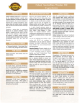
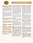
Recreational Vehicles
Gas pressure Regulators & Accessories
2012 EDITION
RE-01
Recreational vehicles
Product index
1 - Introduction
P.4
1.1 • Pressure Gas Regulators
1.2 • Installations
1.3 • Backflow check valve safety device
P.4
P.4
P.5
2 - Two Stage Range - Type 424 NRV
P.6
3 - ASME Range - Type 524AS
P.7
4 - Automatic Changeover Range - Type 924 NRV P.7
4.1 • Start up and usage
4.2 • Advantages of the automatic changeover Type 924 NRV
5 - Gas Accessories
P.8
P.8
P.10
5.1 • Vent cover Type 211
5.2 • Flexible hose Type 501 LP
5.3 • Flexible hose Type 501 HP
5.4 • T-Check Type 413
5.5 • Mounting brackets Type 171
P.10
P.10
P.10
P.10
P.10
LPG & NATURAL GAS REGULATORS
DIVISION
Recreational Vehicles
REGULATORS
LPG & NATURAL GAS REGULATORS
DIVISION
3
Recreational vehicles
1. INTRODUCTION
1.1 Pressure Gas Regulators
Two stage gas regulators are designed and manufactured in accordance to UL 144 requirements (NFPA 1192; paragraph
5.2.15.2). Regulators are used with propane gas appliances functioning at 11 inch WC pressure.
Gas pressure regulators, used in recreational vehicle (RV) installations, have two integrated stages of regulation with
intermediate pressure of 10 PSI (NFPA 1192; paragraph 5.2.15.1).
Depending on the kind of installation these regulators are used for, they can supply gas for a range of calorific power from
100,000 to 160,000 BTU. See technical description of gas appliances.
The second stage of the regulator is equipped with a safety valve Type 1 as per UL 144.
WARNING:
The regulator most be installed with vent hole pointing downwards to allow water to exit.
(See NFPA 1192, paragraph 5.2.15.4).
WARNING:
100 % inspection at Re.Ca. Italy manufacturing unit of the whole range of regulators is undertaken during manufacturing
process as far as:
- setting pressure; see setting point at page 6 and 7 of the present catalogue;
- leakage test at the inlet (high pressure value to be used) and leakage test at the outlet (low and high pressure value to be
used).
1.2 Installations
RV installations can be made on the basis of the following general diagram:
UL 2061
UL 144
Furnace
30000 BTU
Twin Type 424NRV
Inversor Type 924NRV
Water Heater
12000 BTU
Range
29000 BTU
Refrigerator
1500 BTU
Outside grill
10000 BTU
RV installations are supplied by single or double cylinder systems, or by ASME tanks. The integrated second stage regulator
is connected to cylinders through flexible high pressure gas rubber hoses, equipped with fittings in accordance to UL 2061
(NFPA 1192; paragraph 5.2.16.4). Installations of integrated double stage regulators have to be in accordance with
requirements expressed in NFPA 1192, paragraph 5.2.15.
Installations generally supply the following gas appliances:
- Furnace
- Range
- Water Heater
- Refrigerator
- Outside grill
Total
30000 BTU
29000 BTU
12000 BTU
1500 BTU
10000 BTU
81000 BTU
WARNING:
Inside diameter and length of pipes must be calculated to ensure that supplying pressure is sufficient to run the gas
appliances at the same time.
All of the above mentioned gas appliances must run at the same time without any failure.
4
LPG & NATURAL GAS REGULATORS
DIVISION
Recreational vehicles
Gas cylinder and regulator shall be protected by a shelter or in a cylindrical cage, see following diagram (as per NFPA 1192,
paragraphs 5.2.15.6; 5.2.15.7; 5.2.15.8).
Type A - Wall Installation
Type B - ASME Installation
524NRV
924NRV or
424NRV + Inlet 413
501 HP
501 LP
Type C - Cover Installation
501 HP
924NRV or
424NRV + Inlet 413
WARNING:
RV gas piping system must be tested for leakage prior to
delivering vehicle to dealer network. Therefore, setting
pressure test and leakage test have be done by
authorized RV OEM. In case of any detected anomalies,
the gas regulator kit is not likely to be responsible because
the gas regulators are 100% tested while manufacturing.
1.3 Backflow check valve safety device
In accordance with requirements of NFPA 1192, paragraph 5.2.16.3, it is compulsory to have a “backflow check” device for
double cylinder installations:
For Two stage group of regulation:
The device consists of a “T” fitting that prevents gas from flowing, in case one of the inlets of the regulator kit is not
connected to one of the cylinders.
WARNING:
If a simple “T” fitting is used, it is obligatory to use flexible hoses equipped with “backflow check” device.
For automatic changeover:
The “Backflow Check” device can be integrated into the automatic changeover to prevent gas from flowing, in case one
of its inlets is not connected to the cylinder.
WARNING:
If the automatic changeover is not equipped with “backflow check” device, it is obligatory that the «backflow check»
device be provided with flexible hoses.
LPG & NATURAL GAS REGULATORS
DIVISION
5
Recreational vehicles
2. Two Stage Range - Type 424 NRV
424NRV Type
Cover installation
Depending on the type of installation the basic model can
be equipped either with a mounting bracket for “wall
installation”, type A on page 5, or with a mounting bracket
for “cover installation”, type C on page 5. In general plastic
protection is necessary in first and second stage of
regulator for all types of installations.
In double cylinder installations it is necessary to couple the
“T” inlet of the backflow check device. See Accessories at
page 10.
WARNING:
User manual is obligatory in case the regulator is directly
sold to end user. RV OEM must integrate their technical
documentation with the provided instruction sheet.
The Two Stage regulator, Type 424 NRV, is connected to the
RV through a flexible hose 501 LP Type. See Accessories at
page 10.
Technical features:
Inlet connection:
Outlet connection:
Test Point:
Guaranteed Flow:
Setting Point:
Adjustable outlet pressure:
Paint:
Cover and body:
Wall installation
424NRV - Two Stage UL144
First stage setting 0,3 bar
Setting point 11 w.c. 60.000 BTU
1/4 NPT
3/8 NPT
1/8 NPT
103000 BTU/h
11 WC +/- 1 at 60000 BTU
from -1 WC to +2 WC
metallic grey
Zamak Alloy 13 EN 1774
Type
Bracket Model
1 Wall Model
2 Model L
424NRV
How to order 424 NRV TYPE:
Please combine the codes from the above grid together, as follows:
Type + bracket model. E.g.:
6
LPG & NATURAL GAS REGULATORS
424NRV -
DIVISION
2
Recreational vehicles
3. ASME Range - Type 524AS
524AS Type
Technical features:
Inlet connection:
Outlet connection:
Test Point:
Guaranteed Flow:
Setting Point:
Adjustable outlet pressure:
Paint:
Cover and body:
POL.880
3/8 NPT
1/8 NPT
103000 BTU/h
11 WC +/- 1 at 70000 BTU
from -0.5 WC to +1.5 WC
metallic grey
Zamak Alloy 13 EN 1774
524AS - ULl144
First stage setting 0,3 bar
Setting point 11 w.c. 60.000 BTU
The Two Stage Type 524 AS regulator is mounted directly
to tank, connected to the tank valve of ASME container
type. It is connected at its outlet to the installation gas
pipe net. The regulator inlet POL coupling is equipped
with an excess flow valve device.
WARNING:
The regulator must be mounted with vent holes pointing
downward. The cover 211-086 (see page 10) is normally
mounted as protection for the regulator. See type C
installation.
4. Automatic Changeover Range - Type 924 NRV
924NRV Type
Technical features:
Inlet connection:
Outlet connection:
Guaranteed Flow:
Setting Point:
Inversion Pressure:
Adjustable outlet pressure:
Paint:
Cover and body:
Working temperature range:
924NRV - Automatic Changeover not adjistable
Reversal Point 5 PSI
Setting Point 11 w.c. with 70.000 BTU
Pout in w.c.
Depending on the type of installation the basic model
can be equipped either with a mounting bracket for
“wall installation”, type A at page 5, or with a mounting
bracket for “cover installation”, type C at page 5.
WARNING:
User manual is obligatory in case the regulator is directly
sold to end user. The RV OEM must integrate their
technical documentation with the provided instruction
sheet.
The automatic changeover Type 924 NRV is connected
to the RV through a flexible hose 501 LP Type. See
Accessories at page 10.
¼ female NPT or inverted flare
3/8 NPT
160000 BTU/h
11 WC +/- 1 at 70000 BTU
5 PSI (0.35 bar)
from -0.5 WC to +1.5 WC
metallic grey
Zamak Alloy 13 EN 1774
-4°F -122°F (-20°C-50°C)
Setting Point
LPG & NATURAL GAS REGULATORS
DIVISION
7
Recreational vehicles
Bracket with protective cover installation
Wall mounted installation
4.1 Start up and usage
How to turn it on
- Make sure that the Automatic Changeover is connected to the two tank valves with high pressure gas hose. Make sure that
the automatic changeover is mounted above the two tank valves. Open the two tank valves at the same time. This is
fundamental to allow the automatic changeover to ensure the continuous functioning of the gas installation, in case
one of the two cylinder tanks goes empty. The automatic changeover cannot namely pass to the reserve gas tank, if the
tank valve is closed.
Figure 1
How to read the automatic changeover indicator: full gas tank
- When both gas tanks are full, the changeover indicator becomes green, provided that both tanks A and B
A
B
valves are turned on.
- The arrow on the hand-wheel indicates which of the two bottles is used first, this becomes the “service
bottle”. The other gas cylinder is called “reserve bottle”. See picture 1.
Service
Reserve
How to read the automatic changeover indicator: empty gas tank
Figure 2
- When the «service bottle» exhausts, the automatic changeover gets the sense negative pressure (gas
bottle pressure less than 5 PSI). And automatically switches to the reserve bottle to supply the gas installation
as normal. The end user will knows that the service bottle is now empty understands such operation because A
B
the green because indicator turns red. See picture 2.
How to substitute the empty gas tank with the full one
- Turn the tank valve A off and rotate the automatic changeover hand-wheel 180° (picture 3a). If the reserve Service Reserve
Figure 3a
Figure 3b
Figure 3c
Figure 3d
gas tank is full, the indicator will turn green (picture 3b).
- Remove the empty gas tank (picture 3c).
- Install a full gas bottle and make sure to connect the A
B
A
B
A
B
A
B
same to the automatic changeover. Then turn on the
cylinder valve A (picture 3d).
Service
Reserve
Empty
Service
Empty
Service
Reserve
Service
4.2 Advantages of the automatic changeover Type 924 NRV
Easy-to-read changeover indicator
The indicator displays the two different ways of functioning Service/Reserve by changing colour. Reading the indicator
colour is fundamental for the user because he is able to know when to proceed to replace the empty gas tank with the
reserve gas tank. The indicator is designed to guarantee the best reading as possible:
* Far away visibility
* Frontal visibility
* Lateral visibility
Integrated “Back-flow check” device
As the “back-flow check” device is integrated in the automatic changeover 924 NRV Type, the user can apply gas high
pressure hoses which are not equipped with their own back-flow check device. This always provides safety installation, even
if the user replaces gas rubber hoses.
Automatic changeover inversion pressure value
The automatic changeover has to let the service cylinder get exhausted before inverting to the reserve gas tank. The
automatic changeover performs even better at low pressure.
In fact the automatic changeover Type 924 NRV is designed to work with a pressure of inversion at 5 PSI (0.35 bar). This means
that the inner pressure of the service gas cylinder must flow below 5 PSI to make the changeover begin to extract gas from
the reserve bottle.
At this pressure value we know in fact that a propane gas bottle can be considered empty, whichever capacity or
temperature functioning conditions the appliance is designed for.
Remote sound signal -optional onlyAll 924 NRV type changeovers are equipped with a magnetic component placed below the hand-wheel. Thanks to this an
optional electronic sound device can be mounted on the hand-wheel, allowing the end user to hear the sound when the
installation is running with the “reserve” gas tank. Thus the end user knows he/she has to replace the empty gas tank at the
earliest. For more information please call the nearest RV dealer.
8
LPG & NATURAL GAS REGULATORS
DIVISION
Recreational Vehicles
ACCESSORIES
LPG & NATURAL GAS REGULATORS
DIVISION
9
Recreational vehicles
5. ACCESSORIES
5.1 Vent cover Type 211
Model 211-161 - Protection cover
for vent hole on the second stages
of two stage 424NRV and
Automatic Changeover 924NRV
regulators.
Type 1 ACME Nut
5.3 Flexible hose Type 501 HP
1/2" SAE Flare
Model 501-005
1/4" I.D. hose, Type 1 ACME Nut x 1/4" Inverted Flare
1/4" MNPT
Model 501-007
3/8" I.D. hose, 3/8" MNPT x 1/2" SAE Flare
Type 1 ACME Nut
3/8" MNPT
5.2 Flexible hose Type 501 LP
Model 211-086 - Complete
protection cover for Two Stage
ASME Type 524 AS.
1/4" Inverted Flare
Model 211-184 - Protection cover
on the second stage of two stage
424 NRV regulator.
Model 501-006
1/4" I.D. hose, Type 1 ACME Nut x 1/4" MNPT
5.4 T-Check Type 413
Model 413-007 - To be used in double cylinder installations, mounted at the inlet of Two Stage
424NRV. In installations equipped with T-Check standard flexible hoses can be used.
5.5 Mounting brackets Type 171
Model 171-059 - Wall installation
manifold, designed for changeover
Type 942 NRV only.
10
Model 171-061 - Wall installation
manifold for twin regulator Type 424
NRV only.
Model 171-067 - Cover installation
manifold for both twin regulator
Type 942 NRV and changeover Type
424 NRV.
LPG & NATURAL GAS REGULATORS
DIVISION
Cavagna North America, Inc.
50 Napoleon Court, Somerset, NJ 08873 USA
Tel 732.469.2100 * Fax 731.469.3344
email: [email protected]
www.cavagnagroup.com
Recreational Vehicles Rev.2 - Mar ‘12