1
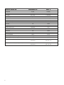
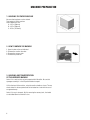
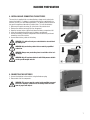
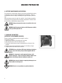
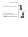
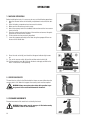
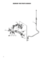
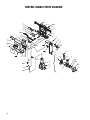
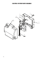
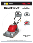
E83039-00
GENIE B APS
™
14” All Purpose
Automatic Scrubber
Operator and Parts
Manual
1001 Brown Avenue • Toledo, Ohio 43607-0127
Customer Service: 888-GO-BETCO • Fax: 800-445-5056 • Technical Service: 877-856-5954 • www.betco.com
1
TABLE OF CONTENTS
RECEIVING THE MACHINE............................................. 3
TECHNICAL SPECIFICATIONS......................................... 4
GENERAL SAFETY REGULATIONS.................................. 5
MACHINE PREPARATION.........................................6 - 11
OPERATION.................................................................. 12
TURNING OFF THE MACHINE....................................... 13
DAILY MAINTENANCE............................................14 - 15
SCHEDULED MAINTENANCE........................................ 16
TROUBLESHOOTING GUIDE......................................... 17
BRUSH AND SELECTION GUIDE................................... 18
PARTS DIAGRAMS AND LISTINGS........................20 - 37
WARRANTY.................................................................. 40
2
RECEIVING THE MACHINE
Immediately check, when receiving the machine, that all the materials indicated on delivery documents have been received and
also that the machine has not been damaged in transit. If it has been damaged, this damage must be immediately reported to
the shipper and also to our customer’s service department. Only acting promptly in this manner will make it possible to receive
missing material and to be compensated for damage.
Serial # Plate
INTRODUCTION
This is an automatic scrubber which, via the mechanical action of the
rotating brush and the chemical action of a water/detergent solution, can
clean any type of hard flooring. As it advances, it also collects the dirt
removed and the detergent solution not absorbed by the floor.
The machine must be used only for this purpose. Even the best machines will only work well if used correctly and kept in good working
order. We therefore suggest you read this instruction booklet carefully and
re-read it whenever difficulties arise while using the machine. If necessary,
remember that our assistance and customer service is always available for
advice or direct intervention.
SYMBOLS USED ON THE MACHINE
Valve symbol
Used to indicate the solenoid valve switch
Power symbol
Used to indicate the machine's power is on
Vacuum motor symbol
Used to indicate the vacuum motor switch
Maximum solution temperature gauge
Located near the solution tank inlet
3
TECHNICAL DESCRIPTION Measurement Unit
Genie™ B
Working width
in (mm)
13.8 (350)
Rear squeegee width
in (mm)
17.3 (440)
ft2/h ( m2/h)
11,300 (1050)
g/m2
-
Battery
-
Maintenance Free, gel battery
Run time
-
Up to 1.25 hours
in (mm)
13.8 (350)
HP
1/3 HP
Work capacity
Water consumption
Brush & Pad (diameter)
Brush motor
Drive type
Forward movement speed
mph (km/h)
Maximum grade
Vacuum motor
semi-automatic
1.9 (3)
2%
HP
1/3 HP
Solution tank capacity
Gal (l)
3 (11.4)
Recovery tank capacity
Gal (l)
3 (11.4)
Weight of empty machine (without battery)
lb (Kg)
85 (38.6)
Weight of empty machine (with battery)
lb (Kg)
135 (61.2)
in x in x in
35 x 17 x 44
(mm/mm/mm)
(889 / 432 / 1118)
in x in x in 35 x 17 x 17
(mm/mm/mm)
(889 / 432 / 432)
Machine dimensions upright (Length / Height / Width)
Machine dimensions stored (Length / Height / Width)
4
GENERAL SAFETY REGULATIONS
The regulations below must be carefully followed in order to avoid harm to the operator and damage to the machine.
• Read the labels on the machine carefully. Do not cover them for any reason and replace them immediately if they are damaged.
• The machine must be used exclusively by authorized and trained personnel.
• When operating the machine be careful of other people.
• The machine is not suitable for cleaning carpets.
• The power cable outlet must be plugged into a grounded power outlet.
• Avoid damaging the power cable by crushing, bending, cutting or stressing it.
• WARNING: do not let the power cable come into contact with the rotating brush.
• Whenever the power cable is damaged, immediately contact a BETCO service center.
• Do not mix different types of detergent as this may produce harmful gases.
• Do not set containers on the machine.
• Machine storage temperature is between -10°F and 130°F, never store outside under humid conditions.
• Operating conditions: room temperature between 33°F and 100°F with relative humidity between 30% to 95%.
• Do not expose the machine to rain.
• Never use the machine in an explosive environment.
• Do not use the machine as a means of transport.
• Never use acidic chemicals which could damage the machine.
• Avoid running the brushes with the machine stopped as this could damage the floor.
• Never vacuum up flammable liquids.
• Never use the machine to gather dangerous powders.
• Use a powder fire extinguisher in case of fire. Do not use water.
• Do not hit against shelving or scaffolding. The operator must always be equipped with the appropriate safety device (gloves,
shoes, helmet, glasses, etc.)
• Do not use the machine on surfaces with an inclination greater than the one shown on the serial plate.
• The machine is designed to wash and dry floors simultaneously. Signal the presence of wet floors with suitable signs.
• If the machine does not work properly, perform routine maintenance. Otherwise, request the assistance of BETCO technical
support.
• When replacing parts ask for ORIGINAL spare parts from your Authorized BETCO Dealer and/or Retailer.
• Always turn off the machine and unplug the power cord whenever maintenance is performed.
• Never remove guards that require tools to remove.
• Never wash the machine with direct or pressurized jets of water or with corrosive substances.
• Have your BETCO service center check the machine once a year.
• To prevent the formation of scale in the solution tank filter, do not store the machine with detergent in the tanks.
• Before using the machine make sure that all doors and covers are positioned as shown in this operating and maintenance
manual.
• When your BETCO machine is ready to be retired, the machine must be disposed of properly. It contains oils and electronic
components. The machine itself was built using totally recyclable materials.
• Use only brushes furnished with the machine or those specified in the user's manual. Use of other brushes can compromise
safety.
• This machine must be operated by trained professionals.
5
MACHINE PREPARATION
1. HANDLING THE PACKED MACHINE
No more than two boxes can be stacked.
Total weight is 150 lbs. per box.
Overall dimensions are:
A: 19.7 in (500 mm)
B: 19.7 in (500 mm)
C: 45.3 in (1150 mm)
2. HOW TO UNPACK THE MACHINE
1. Open the box on the end indicated.
2. Remove the machine from box.
3. Remove the recovery tank.
4. Remove the pad driver.
3. HANDLING AND TRANSPORTATION
OF THE UNPACKED MACHINE
Genie™ B is a machine that can be transported with little effort. Be sure that
squeegee assembly is in the UP position before transport.
Lift the front end of the machine, using the machine handle as a lever. The rear
wheels allow it to be transported and can be loaded on a truck with the use of
an approved ramp.
Genie™ B is easy to transport. By first removing the recovery tank, the handle
can be folded down to minimize its size.
6
MACHINE PREPARATION
4. INSTALLING AND CONNECTING THE BATTERIES
The machine is supplied with an on-board battery charger and a sealed maintenance free battery. If a battery is used other than the one supplied with the
machine, use only a 12 volt AGM or gel battery. The battery must be housed in
the special compartment beneath the solution tank. To insert the batteries:
1. Disconnect the quick connector (1) at the front of the solution tank.
2. Remove the solution tank and place it on the ground.
3. Open the two rear latches (2) that hold down the battery compartment lid.
4. Lower the handlebar forward to open the battery compartment.
5. Position the battery inside the compartment with the terminals positioned
toward the rear of the machine.
6. Connect Betco factory cables to the battery.
WARNING: It is advised to only use sealed batteries to avoid leaking battery acid.
WARNING: Only use battery cables that are made by a qualified
technician.
WARNING: Always wear protective gloves to avoid the risk of serious injury.
WARNING: Only lift and move batteries with lifting means suitable
for the specific weight and size.
5. CONNECTING THE BATTERIES
1. Connect the batteries to the machine using the Anderson plug.
2. Reassemble all of the components.
WARNING: This process must be carried out by qualified personnel.
Incorrect or improper connection of the battery cable can cause
harm to people and objects.
7
MACHINE PREPARATION
6. BATTERY MAINTENANCE AND DISPOSAL
For maintenance and recharging, follow the instructions provided by the battery
manufacturer or only use factory supplied electrical components. There are
many different kinds of chargers according to the type and capacity of the battery.
When the battery reaches the end of its useful life, it must be disconnected by
trained personnel and removed from the battery compartment. Batteries must
be recycled by a certified battery disposal facility.
WARNING: Always wear protective gloves to avoid the risk of serious injury.
WARNING: Only lift and move batteries with lifting means suitable
for the specific weight and size.
7. CHARGING THE BATTERY
(WITH BUILT IN ON-BOARD CHARGER)
Perform a battery charging cycle before using the machine.
To recharge the battery:
1. Make sure the recovery and solution tanks are empty.
2. Move the machine to a 110 volt electrical outlet.
3. Remove the rubber battery charger socket protection on the back of the
machine.
4. Plug the power cable (provided with machine) into the battery charger.
5. Plug the power cable into the electrical outlet.
ATTENTION: If one of the three LED's begin flashing on the battery
charger, refer to the battery charger manual supplied with the
machine.
WARNING: It is important to avoid complete discharge of the
batteries during use. Plan to recharge the batteries within a few
minutes of the battery indicator turning the machine off.
WARNING: Never leave the batteries completely discharged, even
if the machine is not being used.
WARNING: Do not use an open flame or spark near batteries.
8
MACHINE PREPARATION
8. BATTERY DISCHARGE INDICATOR
The battery indicator is digital with 4 fixed positions and a flashing signal. The
numbers that appear on the display represent the approximate charge level.
4 = Maximum Charge
3 = 3/4 Charge
2 = 1/2 Charge
1 = 1/4 Charge
0 = Discharged Batteries (Flashing)
WARNING: A few seconds after the appearance of the flashing "0",
the brush motor will automatically turn off. With the remaining
charge, it is possible to continue using the vacuum motor to finish
drying the surface before recharging.
9. INSTRUMENT PANEL COMPONENTS
The instrument panel components are identified as follows:
1. Main Power / Brush Motor Switch
2. Vacuum Motor Switch
3. Solution Valve Switch
4. Digital Battery Discharge Indicator
10. POSITIONING THE HANDLEBARS
For packaging purposes, the handlebars are positioned in the down location and
must be put into working position.
1. Squeeze the lever on the right side of the machine to release the handle lock.
2. Lift the handle upwards while maintaining pressure on the lever.
3. Attach the recovery tank to the handle tube using the two hooks on the tank.
4. Attach the vacuum hoses to the lid on the recovery tank.
9
MACHINE PREPARATION
11. SOLUTION TANK
The recovery tank must be completely emptied each time the solution tank is
filled.
Ensure the cap is correctly threaded into the solution tank (A).
Ensure that the quick connect fitting is properly connected at the front of the
machine (B).
12. SOLUTION TANK FILLING
Fill the solution tank with clean water at a temperature that does not exceed
120°F (50°C). Add liquid detergent at the concentration and according to the
procedures recommended by the chemical manufacturer. To prevent excess
foam, use a defoaming chemical in the recovery tank. If foam passes through
the vacuum motor, damage will occur and will not be covered under warranty.
WARNING: Always use low-foam detergent. Add defoaming chemical to the recovery tank before starting work to prevent foam
from being generated.
WARNING: Never use acids.
WARNING: Always wear protective gloves to avoid the risk of serious injury.
10
MACHINE PREPARATION
13. RECOVERY TANK
Make sure the recovery tank is empty, otherwise, empty it completely. Check
that it is properly secured to the handle tube and that the hoses are correctly
inserted in the tank elbows. Check the cap to ensure it is properly seated.
14. ASSEMBLING THE BRUSH
To install the brush - (Be sure squeegee is in the 'up' position)
1. Place the brush in front of the machine on the floor.
2. Raise the front of the machine using the handlebar as a lever.
3. Place the front of the machine over the brush, centering the hub into the
clutch plate on the brush.
4. Press the main switch button to power on the machine.
5. Pull the operation lever on the handle to engage the brush to the brush hub.
11
OPERATION
1. MACHINE OPERATION
Before installing the tanks, it is necessary to carry out the following operations:
1. Open the two rear latches to the battery compartment and connect the battery.
2. Close the battery compartment and reconnect the latches.
3. Make sure that the recovery tank is empty.
4. Attach the recovery tank to the handlebar tube and connect the two vacuum
hoses to the lid.
5. Place the solution tank over the base of the machine and connect the quick
connector at the front of the machine.
6. Fill the solution tank as previously described.
7. Lower the squeegee assembly to the floor using the squeegee lift lever on
the rear of the handle tube.
8. Press the main switch (1) and check that the green indicator light comes
on.
9. Turn on the vacuum switch (2) and the solution control switch (3).
10. Pull the operation lever (4) to activate the brush and apply solution to the
floor. The machine is now operating.
2. OVERFLOW DEVICE
The machine has a float in the filter basket that stops vacuum airflow when the
recovery tank is full. When this happens the recovery tank must be emptied.
WARNING: Always wear gloves when doing this operation to protect yourself from contact with hazardous chemicals.
3. FORWARD MOVEMENTS
Forward movement of the machine is assisted by the brush.
WARNING: Always make sure the squeegee is lifted when moving
backwards, even for short distances.
12
TURNING OFF THE MACHINE
13. RECOVERY TANK
To properly turn off the machine after use or before performing any maintenance:
1. Turn off the solution control switch (3).
2. Turn off the vacuum switch (2).
3. Turn off the main switch (1).
4. Raise the squeegee lift lever on the back side of the handle tube.
5. 6. 7. 8. Transport the machine to the location provided to drain water.
Disconnect the vacuum hoses and remove the recovery tank from the machine.
Remove the recovery tank cap and tilt the tank to empty the waste water.
Disconnect the quick connection at the front of the machine and remove the
solution tank.
9. Remove the cap from the solution tank and tilt the tank to dump any remaining
solution.
10. Remove the brush and rinse it with clean water.
WARNING: Always wear gloves when doing this operation to protect
yourself from contact with hazardous chemicals.
WARNING: Never tilt the machine backwards and rest on the handle
if there is water in the recovery tank. This may spill water into the
electrical panel and cause permanent damage to the machine.
13
DAILY MAINTENANCE
1. CLEANING THE RECOVERY TANK
1. Disconnect the vacuum hoses from the recovery tank lid.
2. Detach the recovery tank from the handle tube.
3. Remove the lid and empty the tank.
4. Rinse the float ball filter cage with clean water.
5. Rinse the inside of the tank with clean water.
6. Reassemble the recovery tank.
WARNING: Always wear gloves to protect yourself from contact
with hazardous chemicals.
2. CLEANING THE SQUEEGEE
Verify that the squeegee blades are clean and free from cuts.
This ensures optimum drying.
To clean the squeegee:
A. Raise the front of the machine.
B. Carefully clean the inside of the squeegee shoe.
C. Carefully clean the squeegee blades.
WARNING: Always wear gloves to protect yourself from contact
with hazardous chemicals.
14
DAILY MAINTENANCE
3. REPLACING THE SQUEEGEE BLADES
Examine the condition of the squeegee blades. Replace as necessary. To replace
the blades:
A. Lift the squeegee.
B. Remove the two knobs.
C. Detach the squeegee from the squeegee yoke.
D.Remove the hose from the squeegee hose adaptor.
WARNING: Before carrying out any type of maintenance, disconnect the machine's battery connector.
WARNING: Always wear gloves to protect yourself from contact
with hazardous chemicals.
E. Unscrew the squeegee knobs that hold the band clamps on squeegee shoe.
F. Remove the band clamps and squeegee blades.
G.Replace the squeegee blades and band clamps.
H.Reinstall everything by performing this procedures in reverse.
I. Inspect the squeegee guide wheels to make sure they spin freely and have no
damage. Replace if necessary.
4. BRUSH DISASSEMBLY
A. Lock the squeegee in 'up' position.
B. Lift the front of the machine by pressing down on the handle until the brush
is 2” - 4” off the floor.
C. When the brush is lifted jog the brush motor. The brush releases automatically and falls onto the floor.
WARNING: Always wear gloves to protect yourself from contact
with hazardous chemicals.
15
SCHEDULED MAINTENANCE
1. CLEANING THE SQUEEGEE HOSE
Check the squeegee hose for blockage if the suction is insufficient and at periodic intervals. To clean the hose:
A. Remove the hose end from the squeegee hose adapter.
B. Remove the other end of the hose from the recovery tank.
C. Wash the inside of the hose with clear water, spraying from the end that connects to the tank.
D.Reinstall the hose.
WARNING: Do not wash the hose that goes from the vacuum unit to
the recovery tank. This will damage the vacuum motor!
2. CLEANING THE SOLUTION TANK AND FILTER
1. Disconnect the quick connection at the front of the machine (1).
2. Remove the solution tank from the machine.
3. Unscrew the solution cap (2).
4. Remove the screen filter (3) and rinse with clean water.
5. Rinse the inside of the tank with clean water.
6. Install the tank back on the machine.
WARNING: Always wear gloves to protect yourself from contact
with hazardous chemicals.
16
TROUBLESHOOTING GUIDE
1. ELECTRICAL SYSTEM SAFETY
The machine is equipped with self-resetting thermal safety fuses located in the
electric box beneath the solution tank. These fuses interrupt the power supply
to the brush and suction motor when the machine exceeds the predetermined
current limit. To restore power to the motor, switch off the machine and wait
for the fuses to cool down. If the switch interrupts power supply again, contact
Betco technical service assistance.
2. INSUFFICIENT WATER ON THE FLOOR
A. Verify that the solution tank is clean.
B. Verify that the solenoid valve switch is turned on.
C. Verify the quick disconnect is properly connected.
D.Verify the adjustment of the ball valve that supplies water.
E. Verify the vent pin on the solution tank cap is lowered.
3. THE MACHINE DOES NOT CLEAN WELL
A. Check the condition of the brushes or pad. Replace them as required.
Brushes must be replaced when the tufts are roughly 5/8” (15 mm) long.
4. THE SQUEEGEE DOES NOT DRY THE FLOOR
A. Verify that the squeegee blades are clean.
B. Verify that the vacuum hoses are properly installed and seated on the squeegee.
C. Verify the vacuum hose nozzle is clean.
D.Replace worn squeegee blades.
E. Check squeegee guide wheels for wear or damage.
5. EXCESSIVE FOAM PRODUCTION
Verify that low-foam detergent is being used. Add defoaming chemical to the
recovery tank.
More foam is generated when the floors are not very dirty. Dilute the detergent
more when cleaning floors that are not very dirty.
17
BRUSH SELECTION AND USE
POLYPROPYLENE BRUSHES (PPL)
These are used on all types of floors and offer good wear resistance.
PAD DRIVERS
Pad driver and an floor pad is recommended when cleaning smooth floors.
There are two types of pad drivers:
1. The traditional pad driver is fitted with a series of anchor points that allow the abrasive floor pad to be held while working.
2. The CENTER LOCK type pad driver not only has anchor points, but also a snap-type central locking system made of plastic
that allows the abrasive floor pad to be centered and held with reduced risk of it becoming detached.
18
19
BRUSH DECK PARTS DIAGRAM
25
8
24
6
49
48
28
27
25
12
17
7
31
10
37
39
9
4
34
3
14
42
2
15
23
1
32
33
38
26
21
20
44
22
46
47
43
11
19
45
30
16
5
20
18
36
15
29
35
41
13
BRUSH DECK PARTS LISTING
Item# Part # Description
Qty.
Item# Part # Description
Qty.
1
E81530 Spring, 17, 5x2, 5x69 mm
1
25
E81709 Nyloc Hex Nut, M8 Zinc
4
2
E82845 Spacer
3
26
E83879 Flat Washer M5x11x1 Zinc
2
3
E82844 Clutch Plate
1
27
E82761 Washer 6x12x1.6
1
4
E20503 Spacer
1
28
E81874 Flat Washer M8x17x1.6 Zinc
1
5
E88228 Bushing
1
29
E20395 Flat Washer M14 SS
1
6
E20019 Spacer
1
30
E83903 Shim Washer M14x22x0.3
3
7
E86253 Clutch Flange
1
31
E87290 Shim M37x47x0.3
1
8
E20026 Bearing Shaft
1
32
E81719 Cap
1
9
E20403 Bracket
1
33
E81967 Jam Nut, 1/4" NPT Brass
1
10
E20047 Motor Mount Plate
1
34
E81998 Pan Hd Phil Machine Screw M4x10 SS
3
11
E88366 Tensioner Arm
1
35
E86250 Hex Bolt M5x14 Zinc
2
12
E20553 Clutch Pulley
1
36
E81727 Bracket
1
13
E82710 Hose, 8 OD x 5 ID x L 105
1
37
E81541 Brush Drive Belt
1
14
E81752 Tubing 5 OD x 30 L
1
38
E82467 Solenoid Valve 12VDC
1
15
E83547 M6x16 Bolt, Zinc Hex Head
4
39
E86167 Pipe, 1/4" x 8" Copper
1
16
E86667 Bearing, 6001 2RS
3
41
E82711 Quick Disconnect, Male 1/4"
1
17
E81657 Bearing, 6204 2RS
2
42
E81543 Guard, Vispa
1
18
E82288 Screw, Pan Hd Phil Self Tap
2
43
E81550 Ball Valve, 1/4" NPT Double Female
1
19
E83833 Hex Bolt M8x25 Zinc
1
44
E81551 Elbow, 90 degree 1/4" Brass NPT
1
20
E88042 Flat Hd Soc Machine Screw M6x16 Zinc
1
45
E81552 Fitting, Brass, 1/4" x 7mm"
1
21
E81871 Flat Hd Soc Machine Screw M8x40 Zinc
3
46
E20157 Hex Lug
1
22
E20291 Flat Hd Soc Machine Screw M8x25 Zinc
1
47
E86156 Bushing
1
23
E82256 Nyloc Hex Nut, M5x7 Zinc
2
48
E81553 Carbon Brush
4
24
E83550 Nyloc Hex Nut, M6 Zinc
1
49
E81555 Brush Motor 12VDC 360W
1
21
SQUEEGEE SYSTEM PARTS DIAGRAM
13
18
11
2
12
11
17
14
1
7
5
8
10
9
6
4
3
16
15
17
22
11
12
2
SQUEEGEE SYSTEM PARTS LISTING
Item# Part # Description
Qty.
Item# Part # Description
Qty.
1
E81815 Squeegee Vacuum Adapter
1
11
E81934 Flat Washer M6x12x1.6 SS
1
2
E81897 Bushing
1
12
E81531 Squeegee Support Wheel 24 OD x 12.7 W
4
3
E85792 Squeegee Shoe
1
13
E20701 Squeegee Hose Guard
4
4
E81753 Knob M5
6
14
E20616 Carriage Bolt M5 x 35 SS
2
5
E83870 Squeegee Blade, Front, Shore 33
1
15
E86264 Carriage Bolt M5x25 SS
1
6
E83869 Squeegee Blade, Rear, Shore 33
1
16
E81941 Carriage Bolt M5x30 SS
1
7
E82707 Set Screw Hex Soc Flat End M6x40 SS
1
17
E81896 Carriage Bolt M6x16 SS
1
8
E81755 O-Ring
1
18
E83914 Hex Bolt M6x20 SS
1
9
E81909 Front Squeegee Band Clamp
1
*
E81921 Complete Squeegee Assembly
1
10
E82731 Rear Squeegee Blade Band Clamp
1
23
SQUEEGEE YOKE PARTS DIAGRAM
13
1
4
12
6
7
3
10
5
9
11
14
8
2
24
SQUEEGEE YOKE PARTS LISTING
Item# Part # Description
Qty.
Item# Part # Description
Qty.
1
E87971 Squeegee Yoke Arm
1
8
E83278 Flat Washer M6.5x24x2 Zinc
1
2
E86153 Squeegee Yoke
1
9
E83710 Cotter Pin D2x20 Zinc
1
3
E82839 Squeegee Yoke Pivot
1
10
E83810 Knob
2
4
E86263 Oval Hd Phil Machine Screw M5x35 SS
1
11
E86152 Spacer
1
5
E83834 Hex Bolt M6x35 Zinc
2
12
E20382 Nyloc Hex Nut, M5 x 5 Zinc
1
6
E83550 Nyloc Hex Nut, M6 Zinc
2
13
E82419 Squeegee Lift Cable
1
7
E82761 Washer 6x12x1.6
2
14
E81545 Spring
1
25
MAIN FRAME PARTS DIAGRAM
31
13
26
34
7
15
1
24
44
20
41
25
5
27
19
38
29
42
32
27
14
4
37
39
2
35
22
6
26
11
28
36
10
16
26
21
18
36
9
21
40
43
12
33
23
17
8
3
22
17
30
MAIN FRAME PARTS LISTING
Item# Part # Description
Qty.
Item# Part # Description
Qty.
1
E20272 Bushing
2
23
E86255 Flat Washer M10x21x2 SS
2
2
E20020 Hex Lug
1
24
E88349 SB50 Blue Electrical Connector
2
3
E86269 Bushing
2
25
E89141 Charger Plug Tee Handle
1
4
E20050 Protective Trim Edging
1
26
E81565 Clamp, 4.8x200 Black
6
5
E20587 Clamp Plate
1
27
E20435 Nyloc Hex Nut, M3 SS
8
6
E20053 Bracket
1
28
E20568 Rubber Bumper
2
7
E83944 Sound Deadening Foam
1
29
E86215 Battery Box
1
8
E82456 Hex Bolt M6x14 Zinc
1
30
E86270 Bracket
1
9
E20088 Hex Bolt M6x18 Zinc
1
31
E20258 Battery Box Lid
1
10
E83833 Hex Bolt M8x25 Zinc
2
32
E81538 Vacuum Motor 12VDC 250W
1
11
E20098 Hex Bolt M8x18 Zinc
1
33
E81539 Transport Wheel 200 OD x 42 W
2
12
E20108 Screw, Pan Hd Phil Self Tap M4.8x16 SS
2
34
E81896 Carriage Bolt M6x16 SS
2
13
ET1002 Screw, Pan Hd Phil Self Tap
2
35
E85755 Carriage Bolt M10x50 SS
2
14
E81672 Flat Hd SL Machine Screw M3x10 SS
8
36
E20152 Carriage Bolt M8x20 SS
4
15
E83550 Nyloc Hex Nut, M6 Zinc
3
37
E81540 Carbon Brush
1
16
E81709 Nyloc Hex Nut, M8 Zinc
2
38
E81544 Charger 12VDC 6AMP 120VAC ONB AGM GEL BSB501
17
E81342 Nyloc Hex Jam Nut, M8 SS
4
39
E20461 Hex Bolt M6x90 Zinc
2
18
ET1001 Nyloc Hex Nut, M10 SS
2
40
E20383 Bushing
2
19
E81979 Flat Washer M3x7x0.5 SS
4
41
E20586 Cap
2
20
E82761 Washer 6x12x1.6
3
42
E86199 Latch
2
21
E81874 Flat Washer M8x17x1.6 Zinc
3
43
E87024 Main Frame Weldment
1
22
E88238 Flat Washer, M8x17x1.6 SS
4
44
E82840 Sound Deadening Foam
1
27
SOLUTION AND RECOVERY TANKS PARTS DIAGRAM
2.7
2.4
2.6
2.2
2.8
1
2
5
2.5
3
2.1
2.3
2.9
10
9
11
14
7
13
12
8
6
28
4
15
SOLUTION AND RECOVERY TANKS PARTS LISTING
Item# Part # Description
Qty.
Item# Part # Description
Qty.
1
E81532 Hose, Vacuum 29 D x 1250 L
1
4
E83476 Rivet, M6.4x10 Nylon
4
2
E81534 Recovery Tank Cap ASM
1
5
E81968 Latch
2
2.1 E82853 Filter Flange
1
6
E82712 Quick Disconnect, Female 1/4"
1
2.2 E82381 Gasket Ring
1
7
E81546 Hose, Vacuum 20 D x 1600 L
1
2.3 E81710 Hose Clamp
1
8
E81556 Solution Tank
1
2.4 E81944 Grommet
1
9
E81972 Recovery Tank
1
2.5 E86217 Recovery Tank Cap
1
10
E81548 Solution Tank Cap
1
2.6 E81849 Vacuum Elbow Fitting
1
11
E81549 O-Ring
1
2.7 E81943 Vacuum Elbow Fitting Long
1
12
E81971 Wheel Cap
2
2.8 E86193 Grommet
1
13
E81969 Rubber Cap
1
2.9 E82360 Air Filter/Shutoff
1
14
E82398 Filter, Inlet
1
3
E81963 Flat Hd Soc Machine Screw M5x12 SS
4
15
E85513 Battery Charger Cover
1
29
CONTROL HANDLE PARTS DIAGRAM
32
27
24
7
18
2
17
32
23
25
31
9
5
16
21
11
28
12
30
20
40
36
35
14
22
34
10
7.7
32
26
1
13
39
1
37
33
38
7.6
7.2
7.8
7.1
7.3
7.9
29
4
7.5
6
7.8
15
19
3
30
8
7.5
7.4
CONTROL HANDLE PARTS LISTING
Item# Part # Description
Qty.
Item# Part # Description
Qty.
1
E85770 High Hex Nut M6x13 Zinc
4
17
E82796 Switch, Momentary
1
2
E81793 Spring Pin M6x12 Zinc
3
18
E81791 Plug
1
3
E20273 Connector Tube
1
19
E88173 Flat Hd Phil Machine Screw M6x10 Zinc
2
4
E20620 Handle Tube
1
20
E20364 Button Hd Soc Machine Screw M6x20 Zinc
2
5
E82721 Tie Rod
1
21
E81875 Screw, Pan Hd Phil Self Tap M2.9x9.5 Zinc
4
6
E20593 Handle Pivot Base ASM
1
22
E86250 Hex Bolt M5x14 Zinc
1
7.1 E88761 Pin
1
23
E20567 Bracket
1
7.2 E20519 Spring
1
24
E81792 Switch Lever
2
7.3 E88762 Handle Coupler
1
25
E81766 Lever, Handle Adjustment
1
7.4 E81709 Nyloc Hex Nut, M8 Zinc
1
26
E81994 Support
1
7.5 E20300 O-Ring
2
27
E81744 Handle Bar Console Rear
1
7.6 E20133 Soc Hd Cap Screw M8x45 Zinc
1
28
E86150 Screw, Pan Hd Phil Self Tap M4.8x9.5 SS
4
7.7 E81918 Flat Washer M9x32x2.5 Zinc
1
29
E20302 Grommet
1
7.8 E88763 Geared Support
2
30
E20397 Wire Clamp
1
7.9 E88764 Pivot Gear
1
31
E81676 Control Switch Electrical Board
1
7
E82288 Screw, Pan Hd Phil Self Tap
10
32
E81790 Cap
2
8
E81917 Hex Bolt M8x20 Zinc
4
32
E88428 Plastic Cover
1
9
E20342 Soc Hd Cap Screw M6x40 Zinc
4
33
E20264 Squeegee Lift Lever
1
10
E82835 Soc Hd Cap Screw M6x10 Zinc
4
34
E20544 Plastic Mounting Clip
1
11
E82257 Screw M9 x 16
2
35
E86171 Panel, Rubber Push Button
1
12
E20109 Screw, Pan Hd Phil Self Tap M4.8x19 Zinc
1
36
E81781 Handle Bar Console Front
1
13
E88765 Screw, M5x20
1
37
E20502 Console Decal
1
14
E82317 Hex Jam Nut, M5X3.5 Zinc
1
38
E86132 Spacer
1
15
E81709 Nyloc Hex Nut, M8 Zinc
4
39
E20121 Flat Washer M5x15x1.5 Zinc
1
16
E83710 Cotter Pin D2x20 Zinc
1
40
E20256 Nyloc Hex Jam Nut, M5 Zinc
1
31
ELECTRIC SYSTEM PARTS DIAGRAM
1
3
4
2
7
6
5
32
ELECTRIC SYSTEM PARTS LISTING
Item# Part # Description
Qty.
Item# Part # Description
Qty.
1
E83547 M6x16 Bolt, Zinc Hex Head
1
5
E81787 Ribbon Cable
1
2
E83550 Nyloc Hex Nut, M6 Zinc
1
6
E85788 Electrical Housing
1
3
E82761 Washer 6x12x1.6
1
7
E85771 Electrical Cover
1
4
E81767 Relay Electrical Board
1
33
BATTERY CHARGER DIAGRAM
14
11
30
14
4
11
27
19
19
22
9
10
7
1
31
6
18
24
5
21
29
15
5
17
23
2
3
13
26
28
1
12
24
8
17
25
34
20
16
ELECTRICAL LISTING
Item# Part # Description
Qty.
Item# Part # Description
Qty.
1
E20272 Bushing
2
15
E20363 Flat Hd SL Machine Screw M5x12 SS
4
2
E20579 Protective Trim Edging
2
16
E20322 Hex Nut, M5 SS
4
3
E20050 Protective Trim Edging
1
17
E20435 Nyloc Hex Nut, M3 SS
8
4
E20393 Screw, Pan Hd Phil Self Tap
2
18
E83476 Rivet, M6.4x10 Nylon
4
5
E81672 Flat Hd SL Machine Screw M3x10 SS
8
19
E81537 Contact, SB50
2
6
E83852 Hex Nut, M6x5
2
20
E20568 Rubber Bumper
4
7
E82808 Hex Jam Nut, M8X5 Zinc
4
21
E81896 Carriage Bolt M6x16 SS
2
8
E81979 Flat Washer M3x7x0.5 SS
4
22
E20680 Battery Cable SB50 Blue After S/N 209XXXXX
1
9
E83704 Lock Washer M8x13x2.2 Zinc
4
23
E81544 Charger 12VDC 6AMP 120VAC ONB AGM GEL BSB501
10
E20347 SB50 Blue Electrical Connector
1
24
E20586 Cap
2
11
E88090 Handle Enjoy 365
2
25
E81969 Rubber Cap
1
12
E81565 Clamp, 4.8x200 Black
1
26
E20621 Battery Box
1
13
E82376 Latch, Catch & Clasp 2pc set
2
27
E20167 Battery Box Lid
1
14
E20254 Soc Hd Cap Screw M8x16 Zinc
4
28
E20415 Battery Charger Cover
1
35
ACCESSORIES DIAGRAM
3
8
4
1
13” Pad
Clutch Plate
14” Pad
Medium Brush
STD General Brush
5
Heavy Brush
6
7
2
36
ACCESSORIES LISTING
Item# Part # Description
Qty.
Item# Part # Description
Qty.
1
E82367 Center Lock
1
5
E83863 Brush, General Scrub 0.3 mm PPL
1
2
E82438 Power Cord
1
6
E82526 Brush, Medium Scrub 0.4 mm PPL
1
3
E82408 Pad Driver
1
7
E81608 Brush, Heavy Scrub 0.6 mm PPL
1
4
E88140 Pad Holder 14" STD
1
8
E81711 Clutch Plate
1
37
38
39
BETCO US WARRANTY POLICY
10 year coverage
3 Year Coverage
1 Year Coverage
Subject to the conditions stated below,
Betco warrants parts and labor on
rotationally molded polyethylene tanks/
housings and injection molded vacuum
head assemblies to be free from defects
in materials and workmanship for
a period of ten years to the original
purchaser.
Subject to the conditions stated below,
Betco warrants parts and labor on all
other Betco components to be free from
defects in materials and workmanship
for a period of three years to the original purchaser.
Subject to the conditions stated below,
Betco offers a limited warranty on parts
and labor on the following equipment:
parts and accessories to be free from
defects in materials and workmanship
for a period of one year to the original
purchaser.
• PowerUp™ 14 Upright Vacuum: #E29990-00
• Bac Pac Lite Vacuum: #85903-00
• FiberPRO® Floor Dryer: #85507-00
• WORKMAN™ Series Vacuums:
#85024-00, #85025-00, #83012-00,
#85027-00
• All Tools and Accessories
• All Battery Chargers
• All Batteries are pro-rated for 1 year
Allowable Travel Time Warranty Reimbursement:
Eligible equipment: All battery and propane powered equipment products. Warranty period: 90 days from date of sale to the
original purchaser. A maximum 180 mile round trip at 50 cents per mile will be allowed for warranty consideration.
Propane Machine Warranty:
Kawasaki engines are warranted by Kawasaki for a period of 2 years against manufacturer defects. All other components
(except wear items)* are warranted by Betco for a period of 3 years.
*Wear Items exempt from Warranty consideration include but may not be limited to: power cords, transport wheels,
vacuum bags, belts, squeegee blades, pad drivers, clutch plates, handle grips, filters, screens, throttle cables, brushes
and carbon brushes.
Subject to the conditions and exceptions stated in this warranty, Betco warrants the Betco products to be free from defects in
material and workmanship, under normal use and service, for the periods listed under the warranty policy to the original purchaser. At any time during the warranty period, Betco will furnish replacement parts for the Betco parts to the original purchaser. Such parts will be furnished and charged including transportation costs, to the original owner through any Betco authorized
Service Distributor. If the original part is returned within the warranty policy period from date of delivery for inspection by
Betco and is found to be defective the owner will be credited for the cost of replacement parts plus shipping and handling.
Replacement parts that have become defective through wear or abuse are not included in this warranty.
This warranty does not apply to damage or defect caused by accident, misuse. Negligence, fire, or to any Betco product which
has been serviced or repaired by other than an authorized Betco Service Distributor or Betco factory personnel. This warranty
is void if products are used for any purpose other than that which was intended. There are no other warranties expressed or
implied. In no event shall Betco be liable for incidental or consequential damages or any damage to person or property. (Please
note some states do not allow the exclusion or limitations for incidental and consequential damages).
40
1001 Brown Avenue • Toledo, Ohio 43607-0127
Customer Service: 888-GO-BETCO • Fax: 800-445-5056 • Technical Service: 877-856-5954 • www.betco.com
92156-92 Sept15F