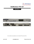
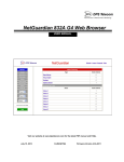
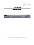
1
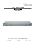
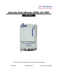
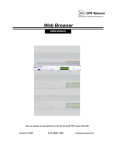
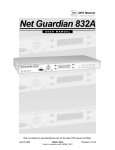
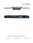
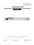
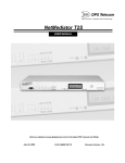
NetDog 82IP G2
USER MANUAL
Visit our website at www.dpstelecom.com for the latest PDF manual and FAQs.
September 25, 2008
D-OC-UM073.07110
Firmware Version 4.0
Revision History
September 25, 2008
Added diagrams on biasing alarm points.
March 7, 2007
NetDog 82IP G2 (D-OC-UM073.07110)
released. Supports Firmware Version 4.0.
This document contains proprietary information which is protected by copyright. All rights are reserved. No part of this
document may be photocopied without prior written consent of DPS Telecom.
All software and manuals are copyrighted by DPS Telecom. Said software and manuals may not be reproduced, copied,
transmitted or used to make a derivative work, by either mechanical, electronic or any other means in whole or in part,
without prior written consent from DPS Telecom, except as required by United States copyright laws.
© 2007 DPS Telecom
Notice
The material in this manual is for information purposes and is subject to change without notice. DPS Telecom shall not be
liable for errors contained herein or consequential damages in connection with the furnishing, performance, or use of this
manual.
Contents
Visit our website at www.dpstelecom.com for the latest PDF manual and FAQs
1 NetDog 82IP Overview
1
2 What's New in the NetDog-82IP G2
2
3 About This Manual
3
4 Shipping List
3
5 Optional Accessories
4
6 Specifications
5
7 Hardware Installation
6
7.1 Tools Needed
6
7.2 Mounting
7
7.3 Power Connection
8
7.4 LAN Connection
9
7.5 Telco Connection
9
7.6 Alarm and Control Relay Connections
10
8 Front Panel LEDs
12
9 Configuring the NetDog
13
10 Connecting to the NetDog
13
10.1 ... via Craft Port
13
10.2 ... via LAN
14
11 TTY Interface
15
11.1 Menu Shortcut Keys
15
11.2 Unit Configuration
15
11.2.1 Ethernet Port Setup
15
11.2.2 Edit PPP Port
17
11.3 Monitoring
11.3.1 Monitoring the NetDog
17
17
11.3.1.1 Monitoring Base Alarms
11.3.1.2 Monitoring Ping Targets
18
11.3.1.3 Monitoring and Operating Relays (Controls)
11.3.1.4 Monitoring Analogs
19
11.3.1.5 Monitoring System Alarms
11.3.1.6 Monitoring the Accumulation Timer
19
18
19
20
11.3.2 Viewing Live Target Pings
21
11.3.3 Proxy Menu
21
11.3.4 Event Logging
21
11.3.5 Backing Up NetDog Configuration Data via FTP
22
11.3.5.1 Reloading NetDog Configuration Data
23
11.3.6 Debug Input and Filter Options
12 Reference Section
12.1 Display Mapping
12.1.1 System Alarms Display Map
24
25
25
27
12.2 SNMP Manager Functions
29
12.3 SNMP Granular Trap Packets
31
13 Frequently Asked Questions
32
13.1 General FAQs
32
13.2 SNMP FAQs
33
13.3 Pager FAQs
34
14 Technical Support
37
1
1 NetDog 82IP Overview
Fig. 1.1. The NetDog has all the tools you need to manage your remote site
The NetDog 82IP G2 — The Intelligent RTU for Complete Site Management
The NetDog 82IP G2 is a RoHS-compliant, LAN-based, SNMP/DCPx remote telemetry unit. The NetDog has all
the tools you need to manage your remote sites, including built-in alarm monitoring, paging and email
capabilities that can eliminate the need for an alarm master.
With the NetDog, you can:
· Monitor 8 alarms, 32 ping alarms, and (with optional analog inputs) 2 analog alarms
· Monitor ambient temperature with 2 temperature sensors (Internal and External)
· Monitor 2 Analog Channels
· Control remote site equipment via 1 serial port and 2 control relays
· Monitor your remote site from anywhere using the NetDog's built-in Web Browser Interface.
· Automatically send pager and email alarm notifications 24/7.
· Access via dialup to view status or connect to other equipment through craft serial port (up to 115,200
baud)
· Monitor discrete and analog alarms.
· Ping IP network devices and verify that they're online and operating.
· Report alarms to multiple SNMP managers or the T/Mon NOC Alarm Monitoring System (support for
SNMP v1, SNMP v2c, and SNMP v2c Inform trap).
· Report alarms via LAN or dial-up connection.
Stand-alone local visibility
You don't need an alarm master unit to monitor your site with the NetDog. With the NetDog's built-in Web
Browser Interface, you can access the NetDog, view alarms and control remote site devices from any computer
anywhere in your network.
24/7 pager and email alerts - no master needed
Out of the box, the NetDog supports 24/7 pager and email reporting. Send alarms directly to maintenance
technicians in the field, even when no one's in the office.
Reports to multiple SNMP managers and T/Mon NOC simultaneously
The NetDog reports to both the T/Mon NOC Alarm Monitoring System and any SNMP manager. You can
simultaneously forward alarms from the NetDog to T/Mon NOC and multiple SNMP managers at multiple IP
addresses.
2
2 What's New in the NetDog-82IP G2
The NetDog-82IP Series adds these new features:
SNMP v2c Support and Robust Message Delivery
NetDog-82IP supports SNMP v2c, and the SNMP INFORM command, which permits robust delivery of alarm
notification to your SNMP manager. The NetDog G2 supports serial baud rates up to 115,200, analog readings
accurate to within +/- 1%, SNMPv2, and SNMPv2c Inform.
2 Analog Channels
The NetDog-82IP has 2 analog channels that can be utilized for monitoring humidity, raw voltage etc.This is an
optional hardware configuration and is not included for all units.
2 Temperature Sensors (Internal and External)
The NetDog's internal and external temperature sensors monitor the ambient temperature. The internal
temperature sensor measures a range of 32° F to 140° F (0° C to 60° C) within an accuracy of ± 1°. The external
temperature sensor provides external temperature readings by plugging the sensor into the Temp port on the
NetDog 82IP G2's front panel. This is an optional hardware configuration and is not included for all units.
Alarm Point Grouping
Each NetDog-82IP Alarm point can be assigned to one of eight groups, which are identified with a user-defined
label. Some of the ways you can use Alarm Point Grouping include:
Alarm Severity Levels:
Configure the NetDog-82IP to indicate assigned alarm security
levels like Critical, Major, Minor and Status in a variable
binding within the SNMP TRAP or INFORM message — so
alarms can be sorted by severity even if your SNMP manager
doesn't support severity levels.
Two Sets of Alarm Severity Levels:
With 8 alarm groups to work with, you can easily create two
different sets of severity levels. For example, you could separate
power alarms (rated from Critical to Status) from environmental
alarms (also rated Critical to Status).
Custom Virtual Alarms:
Create virtual alarms based on easy formulas like All security
alarms or Critical power alarms.
Flexible Custom Derived Controls:
NetDog-82IP lets you create Derived Controls formulas based
on Alarm Point Groups.
Granular Pager and Email Notification:
Selectively assign alarm points to specific pager and email
notification recipients. The NetDog-82IP can be configured to
send pager notifications only for Critical or Major alarms — or
you can send power alarms to repair technicians and intrusion
alarms to a security guard.
Global Support for Dual SNMP Managers
NetDog-82IP supports sending all SNMP TRAP and INFORM notifications to two global SNMP managers. This
makes it easier to configure a secondary SNMP manager and frees up your NetDog-82IP configuration for
additional notification devices and more flexible alarm reporting. You can easily send an alarm to your primary
SNMP manager at the NOC; to a secondary backup SNMP manager at another location; to the pager of the
on-call technician; and the email inbox of the technician's supervisor.
3
Reset the NetDog-82IP Event Log
The NetDog-82IP Event Log has been enhanced to support new NetDog-82IP features:
• You can reset the Event Log, to clear old alarms from the display.
• You can reset the Event Log by Alarm Point Group; for example, clear power alarms while retaining intruder
alarms.
Alarm Sync Makes Turnup and Testing Easy
NetDog-82IP also provides a new command to re-synchronize all alarms. This command clears all alarms, so that
a new notification is sent for all standing alarms. You can easily test alarm connections during turnup without
rebooting the NetDog-82IP unit.
3 About This Manual
There are two separate user manuals for the NetDog 82IP G2: the Hardware Manual (which you're reading now)
and the NetDog 82IP G2 Web Interface User Manual.
This Hardware Manual provides instructions for hardware installation and using the TTY interface. The Web
Interface User Manuals, included on the NetDog Resource CD, provide instructions for configuring the NetDog
using the Web Interface.
4 Shipping List
While unpacking the NetDog, please make sure that all of the following items are included. If some parts are
missing, or if you ever need to order new parts, please refer to the part numbers listed and call DPS Telecom at
(800) 622-3314.
NetDog 82IP G2
D-PK-NGDG4-12001
NetDog 82IP G2 Hardware
Manual D-OC-UM073.07110
NetDog 82IP G2 Resource CD
(includes manuals, MIBs, and software)
DB9M-DB9F Download Cable 6 ft.
D-PR-045-10-A-04
Ethernet Cable 14 ft.
D-PR-923-10A-14
Telephone Cable 6 ft.
D-PR-045-10A-01
4
'
Rack Ear
Four 3/8" Hex Nuts
Four 6-32 x 3/8" Ear Screws
Four Standard Rack Screws
Four Metric Rack Screws
Two 1/2-Amp GMT Main Power Fuses
Large Power Connector Plug for Main Power
Pads
5 Optional Accessories
NetGuardian SiteCAM
D-PK-CAMRA-12001.00001
The NetGuardian SiteCAM provides streaming video security surveillance of remote sites. The SiteCAM
connects to a separate 10/100BaseT hub. SiteCAM video can be accessed directly from the NetDog's Web
Browser Interface. Up to four cameras can be supported.
External Temperature Sensor
D-PR-991-10A-07
The external temperature sensor provides external temperature readings by plugging the sensor into the TEMP
port on the NetDog 82IP G2's front panel.
5
6 Specifications
Discrete Alarm Inputs:
4 (Hardware configured: dry contact, contact-to-ground,
TTL internally-based, TTL externally-based)
Analog Alarms:
2 (optional)
Analog Input Range: (–94 to 94 VDC or 4 to 20 mA)
Temperature Sensors:
2 (optional) Internal and External
Control Relays:
Maximum Voltage:
Maximum Current:
2 Form A
60 VDC/120 VAC
1 Amp, AC/DC
Ping Alarms:
32
Protocols:
SNMPv1, SNMPv2c, DCPx, DCPf, TRIP
SMTP, TAP
Interfaces:
1 DB9 RS232 Craft Port
1 RJ45 10BaseT Ethernet port
1 RJ11 telco jack
2.5mm stereo jack for optional external temperature sensor
24 screw-down connectors and blocks (28 with analogs option)
Dimensions:
1.75"H x 10.52"W x 6.92"D (4.5 cm x 26.72 cm x 17.57 cm)
Weight:
1 lb. 8 oz. (0.81 kg)
Mounting:
Wall or rack
Power Input:
–48VDC (–40 to –70 VDC)
(Optional) –24 VDC (–18 to –36 VDC)
(Optional) Wide Range –24/–48 VDC ( –18 to –72 VDC)
Current Draw:
200 mA
Fuse:
1/2 amp GMT for power inputs
Modem:
33.6 K internal
Visual Interface:
4 bicolor LEDs
14 unicolor LEDs
Audible Notification:
None
Operating Temperature:
32°–140° F (0°–60° C)
Operating Humidity:
0%–95% noncondensing
RoHS 5 Approved
6
7 Hardware Installation
7.1 Tools Needed
To install the NetDog, you'll need the following tools:
Phillips No. 2 Screwdriver
Small Standard No. 2 Screwdriver
Wire Strippers/Cutter
PC with terminal program (i.e. HyperTerminal)
NOTE: To install the NetDog in one of the wall-mount configurations, you will also require a wrench or driver
capable of tightening 3/8" hex nuts.
7
7.2 Mounting
Fig. 6.2.2. Rear View of NetDog
Fig. 6.2.1. The NetDog can be wall- or
rack-mounted
Wall-Mounting Instructions
Depending on how your NetDog was ordered, you will attach wall-mount flanges to both sides of the NetDog in
one of two ways:
1) Place the flange over the protruding screws and affix it
with two of the provided 3/8" hex nuts
2) Affix the flange to the NetDog with two of the
provided 6/32 screws (NOTE: screws longer
than those provided may contact the internal
components of the NetDog, adversely affecting
normal operation).
After flanges have been attached to the NetDog, mount it in the appropriate location with 2 screws through each
flange.
Rack-Mounting Instructions
The NetDog mounts onto one side of a 19" or 23" rack using the provided rack ear for either size. The ear can be
rotated 180 degrees during installation to adjust the position of the NetDog relative to the rack. Attach the
appropriate rack ear to one side of the NetDog, then attach ear to the rack in the desired location.
8
7.3 Power Connection
Fig. 6.3.1. Power connector and fuse.
The NetDog has one screw terminal barrier plug power connector, located on the left side of the back panel. (See
Figure 6.3.1.)
Before you connect a power supply to the NetDog, test the voltage of your power supply:
·
Connect the black common lead of a voltmeter to the ground terminal of the battery, and connect the red
lead of the voltmeter to the battery's –48 VDC terminal. The voltmeter should read between –43 and –
53 VDC. If the reading is outside this range, test the power supply.
To connect the NetDog to a power supply, follow these steps:
1. Remove the fuse from the back panel of the NetDog. Do not reinsert the fuse until all connections to
the unit have been made.
2. Remove the power connector plug from the Power Connector. Note that the plug can be inserted into the
power connector only one way — this ensures that the barrier plug can only be reinserted with the
correct polarity. Note that the –48V terminal is on the left and the GND terminal is on the right.
3. Use the grounding lug to properly ground the unit.
4. Insert a battery ground into the power connector plug's right terminal and tighten the screw; then
insert a –48 VDC line to the plug's left terminal and tighten its screw.
5. Push the power connector plug firmly back into the power connector. If the power feed is connected
correctly, the Power LED on the front of the unit will light GREEN. If the polarity of the power feed is
reversed, the Power LED will not light.
6. Reinsert the fuse to power the NetDog. The front panel LEDs will flash RED and GREEN.
9
7.4 LAN Connection
Fig. 6.4.1. Ethernet port
The NetDog has one 10BaseT Ethernet port.
The 10BaseT port requires a standard RJ45 Ethernet cable. If the IP connection is OK, the LNK LED on the
front of the unit will light SOLID GREEN when the cable is connected.
RJ45 Ethernet Connection
8
7
6
5
4
3
2
1
Receive In– (RI–)
Receive In + (RI+)
Transmit Out– (TO–)
Transmit Out + (TO+)
Fig. 6.4.2 Ethernet port pinout
The pinout for the Ethernet port is shown in Figure 6.4.2, above.
7.5 Telco Connection
Fig. 6.5.1. Telco jack
The rear panel telco jack (see Figure 6.5.1) connects the NetDog internal modem to a standard phone line for
dial-up access and pager alarm notification.
RJ11 Phone Line Connection
4
3 Ring
2 Tip
1
Fig. 6.5.2 Telco jack pinout
10
The pinout for the Telco jack is shown in Figure 6.5.2, above.
7.6 Alarm and Control Relay Connections
Fig. 6.6.1. Alarm and control relay connectors.
The NetDog's discrete alarm inputs, control relay outputs, and (optional) analog alarm inputs, and fuse alarm
output are connected through the screw-lug terminals on the front panel.
11
How to Bias Alarm Points
Fig. 6.6.2 Alarm inputs can be configured with
jumpers A through F
Fig. 6.6.3 Circuit board jumper designations, located in
the lower right area of the circuit board.
Fig. 6.6.4 Each alarm input has four
configuration options.
Example: If connecting alarm points to a dry contact relay, look at the dry contact example at the top of Fig.
6.6.4. Be sure to set jumpers A and C, then bring out the leads from 1A and 1B to both contacts of the relay.
12
8 Front Panel LEDs
Fig. 7.1. Front panel LEDs
The NetDog's front panel LEDs indicate communication and alarm reporting status. LED status messages are
described below in Table 7.A.
LED
Net
Relay 1
Relay 2
Alarms 1-8
Modem
Craft
Config
Power
FA
Status
Description
Blink Green
Transmit over Ethernet port from processor
Blink Red
Solid Green
Solid Green
Solid Red
Blink Green
Blink Red
Blink Green
Blink Red
Blink Green
Blink Red
Receive from Ethernet port to processor
Relay 1 is latched
Relay 2 is latched
Associated alarm is in alarm state
Transmit to internal dialup modem
Receive from internal dialup modem
Transmit
Receive
Valid config.
Invalid config.
Solid Green
Solid Red
Power connected to unit
Fuse Failure
*NOTE: Alarm must be configured for notification to be reflected in LED
Table 7.A. Front panel LED Status message descriptions
13
9 Configuring the NetDog
The NetDog must be provisioned with log-on passwords, alarm descriptions, port parameters, ping targets,
control descriptions, and other system information. You can provision the NetDog using the Web interface. The
NetDog also supports a limited TTY interface for configuring some basic options. (For full instructions on
configuring the NetDog, see the web configuration guide on the NetDog Resource CD.)
You can provision the NetDog either locally through the craft port or remotely through a LAN connection.
However, to access the NetDog via LAN you must first make a temporary connection to the NetDog and assign it
an IP address on your network. For more information, see Section 9, "Connecting to the NetDog."
10 Connecting to the NetDog
10.1 ... via Craft Port
Fig. 9.1.1. NetDog Craft Port
The simplest way to connect to the NetDog is over a physical cable connection between your PC's COM port and
the NetDog's craft port.
Note: You must be connected via craft port or Telnet to use the TTY interface.
Make sure you are using the straight through (1 to 1) Male to Female DB9-DB9 download cable provided with
your NetDog to make a craft port connection.
For initial configuration, use a terminal emulator such as HyperTerminal. If using Windows Operating System,
use the following to access HyperTerminal:
• Click on Start
• Select Programs
• Select Accessories
• Select Communications
• Select HyperTerminal
Connect using COM1
Select the following COM port options:
• Bits per second: 9600
• Data bits: 8
• Parity: None
• Stop bits: 1
• Flow control: None
Ensure that the CRF led flashes red. This can be done by typing any characters once the terminal is setup and the
PC is connected to the NetGuardian's craft port.
14
When a connection is established (sometimes accompanied by receipt of a hex byte), type DPSCFG, then press
Enter. If this does not give you a password prompt, you may not be typing fast enough. If this is the case, then
your second option is to press the 'Menu' button on the front panel of the NetGuardian. Scroll down to 'Run
Config.' and press 'Select.' You should now see your password prompt. Type your password at the prompt and
press Enter to activate the configuration menu. The default password for the NetGuardian is "dpstelecom".
Press 'Enter' to activate the Configuration menu.
You can perform limited configuration tasks via the craft port — DPS suggests connecting via the craft port just
to configure the NetDog's LAN IP address, and then do the rest of your configuration via a LAN connection.
10.2 ... via LAN
Fig.9.2.1. Ethernet port
You can also connect to the NetDog over a LAN connection. This is a very convenient way to provision multiple
NetDog units at multiple locations.
To connect to the NetDog via LAN, all you need is the unit's IP address (Default IP address is
192.168.1.100).
If you have physical access to the NetDog, the easiest thing to do is connect to the unit through the craft port
and then assign it an IP address. Then you can complete the rest of the unit configuration over a remote LAN
connection, if you want. For instructions, see Section 9.1, "Connecting to the NetDog via Craft Port."
If you DON'T have physical access to the NetDog, you can make a LAN connection to the unit by temporarily
changing your PC's IP address and subnet mask to match the NetDog's factory default IP settings. Follow these
steps:
1. Look up your PC's current IP address and subnet mask, and write this information down.
2. Reset your PC's IP address to 192.168.1.200.
3. Reset your PC's subnet mask to 255.255.0.0. You may have to reboot your PC to apply your changes.
4. Once the IP address and subnet mask of your computer coincide with the NetDog's, you can access the
NetDog via a Telnet session or via Web browser by using the NetDog's default IP address of
192.168.1.100.
5. Provision the NetDog with the appropriate information, then change your computer's IP address and
subnet mask back to their original settings.
15
11 TTY Interface
Fig. 10.1. The TTY interface initial configuration screen
The TTY interface is the NetDog's built-in provision controls for basic configuration of the NetDog. Configure
the NetDog's Ethernet port settings, monitor the status of base and system alarms, operate control relays, view
live ping targets, and view debug or create proxy connections to other ports. For more advanced configuration
tools, please use the Web Browser Interface.
To use the TTY interface with the NetDog, all you need is any PC with terminal emulation software (i.e.
Hyperterminal) and a connection to the NetDog. This connection can be a direct connection to the NetDog's front
panel craft port or a remote connection via Telnet or dial-up.
Some initial software configuration must be performed before you can use a remote connection to the NetDog.
For Telnet, connect to the NetDog's IP address at port 2002 to access the configuration menus after initial
LAN/WAN setup. Telnet sessions are established at port 2002, not the standard Telnet port as an added
security measure.
The TTY interface is primarily used for configuring and provisioning the NetDog, but you can also use it to ping
IP targets and view system statistics.
NOTE: The TTY default password is "dpstelecom".
11.1 Menu Shortcut Keys
The letters before or enclosed in parentheses ( ) are menu shortcut keys. Press the shortcut key to access that
option. Pressing the ESC key will always bring you back to the previous level. Entries are not case sensitive.
11.2 Unit Configuration
11.2.1 Ethernet Port Setup
The NetDog must be assigned an IP address before you will be able to connect via LAN/WAN using a Telnet
client or a Web browser. To connect via LAN, the minimum configuration requires setup of the IP address and
subnet mask. Minimum WAN configuration requires that the default gateway be set as well. Follow the
instructions below to configure the NetDog's IP address, subnet mask, and default gateway.
16
Fig. 10.2.1.1. Configure the Ethernet port parameters
1. Once a connection is established, the NetDog will respond with "Password."
2. Type the default password, "dpstelecom," then press Enter.
Note: DPS strongly recommends changing the default password.
3. The NetDog's main menu will appear.
4. Type C for the C)onfig menu.
5. Type E for E)dit menu.
6. Type N for Network settings.
7. Configure the unit address, subnet mask, and default gateway.
8. ESC to the main menu.
9. When asked if you would like to save changes, type Y (yes).
10. Reboot to save the new configuration to the NetDog.
11. Now you can connect to the NetDog via LAN and complete the configuration.
17
11.2.2 Edit PPP Port
Choose P)PP to edit your PPP port in TTY Interface. You can choose a baud rate, depending on what device has
been chose for the PPP port.
Fig. 10.2.2.1 Edit your PPP port
If you are using a modem for the PPP port, then choose mo(D)em for the modem option to define the modem
initialization strings.
11.3 Monitoring
11.3.1 Monitoring the NetDog
Connect a PC running VT100 terminal emulation software to the craft port or connect via LAN using a Telnet
client with VT100 emulation to port 2002 to reach the monitor menu selection. This section allows you to do full
system monitoring of the NetDog, including: all alarms, ping information, relays, analogs, and system status.
Fig. 10.3.1.1. The monitor menu allows status checking on all elements
18
11.3.1.1 Monitoring Base Alarms
View the status of the device connected to the discrete alarms from the M)onitor menu > A)larms option. Under
Status, the word Alarm will appear if an alarm has been activated and Clear will appear if an alarm
condition is not present. If groups are used the user defined status will be displayed.
Fig. 10.3.1.1.1. This example shows the discrete alarms
11.3.1.2 Monitoring Ping Targets
View the status of all your ping targets from the M)onitor menu > P)ing targets option. This screen displays the
ping target ID, description, and IP address. Under Status the word Alarm will appear if an alarm has been
activated and Clear will appear if an alarm condition is not present.
Fig. 10.3.1.2.1. The Ping info submenu allows you to change ping targets
19
11.3.1.3 Monitoring and Operating Relays (Controls)
The NetDog comes equipped with 2 relays that can be used to control external devices. Monitor the status of
your relays from the M)onitor menu > re(L)ays option.
Fig. 10.3.1.3.1 The NetDog's two relays can be operated from this screen
11.3.1.4 Monitoring Analogs
View the current reading and the alarm status of your analog devices from the M)onitor menu > a(N)alogs
option. The value shown is a snapshot of the channels measurement, not a real-time reading. Refresh the readings
by re-selecting the analogs option. Alarm status indicates that a preset threshold has been crossed and is
designated by an x.
The two analog measuring inputs are set to measure voltage as the factory default. If your sensor's output is
current, change the appropriate analog shunt to the current measuring position. The scaling worksheet in the
provisioning section converts all readings shown here into native units, such as degrees Celsius or percent
relative humidity.
Fig. 10.3.1.4.1. This display allows you to monitor the NetDog's two analog inputs
11.3.1.5 Monitoring System Alarms
View the status of the NetDog's system alarms from the M)onitor menu > S)ystem option. Under Status, the
word Alarm will appear if an alarm has been activated and Clear will appear if an alarm condition is not
present. See Appendix, "System Alarm Descriptions," for more information. If groups are used the user defined
status will be displayed.
20
Fig. 10.3.1.5.1. System Alarms can be viewed from the M)onitor menu > S)ystem option
11.3.1.6 Monitoring the Accumulation Timer
The Accumulation Timer keeps a running total of the amount of time a point is in an alarm state. An alarm point
that exceeds a user defined threshold will trigger a Accumulation Event system alarm. Refer to Figure
13.3.1.7.1. and Table 13.3.1.7.A to define the accumulation timer.
Fig. 10.3.1.7.1. Monitor and reset the Accumulator Timer
Field
Description
Display and Point
Reference
Indicates which alarm point is to be monitored.
Point Description
The user-defined description of the monitored alarm point.
Point Status
The current status of the monitored point.
21
Event Threshold
Amount of time allowed to accumulate before the system alarm,
“Accumulation Event” is triggered. Note: Maximum is 45 days.
Accumulated Time
The total time the monitored point has been in an ALARM state.
Accumulated Since
Indicates the last time the accumulation timer was reset.
Reset Accumulation
Timer
Placing a check mark here will reset the timer when the user presses the
Submit button.
Table 10.3.1.7.A. Field descriptions in the Accumulator Timer Settings
11.3.2 Viewing Live Target Pings
Choose P)ing to ping any of the NetDog's user defined IP addresses. Then enter the ID number (1-32) of the IP
address or enter any IP address to ping.
Fig. 10.3.2.1. Continuously ping an IP address that has been defined in the NetDog's ping table
11.3.3 Proxy Menu
You can create proxy connections to reach-through to the craft port or modem port from the P)roxy menu. You'll
be able to monitor and control additional devices via proxy connection to the NetDog.
To cancel the proxy connection wait a half second, then quickly type @@@ and press ENTER.
Fig. 10.3.3.1. Access devices connected to the Craft Port and Modem through M)onitor menu > P)roxy option
11.3.4 Event Logging
Choose E)vent log to view the up to 100 events posted to the NetDog; including power up, base and system
alarms, ping alarms, analog alarms, and controls. Posted events for the various alarms include both alarm and
clear status. Refer to Table 13.3.4.A for event log field descriptions.
Note: All information in the event log will be erased upon reboot or a power failure.
22
Fig. 10.3.4.1. Monitor the last 100 events recorded by the NetDog from the M)onitor menu > E)vent log option
Event Log Field
Evt
Date
Time
Grp
State
PRef
Description
Description
Event number (1–100)
Date the event occurred
Time the event occurred
Alarm Group
State of the event (A=alarm, C=clear)
Point reference (See Appendix A for display descriptions).
User defined description of the event as entered in the alarm point
and relay description fields.
Table 10.3.4.A. Event Log field descriptions
11.3.5 Backing Up NetDog Configuration Data via FTP
1. From the Start menu on your PC, select RUN.
2. Type "ftp" followed by the IP address of the NetDog you are backing up (e.g. ftp 126.10.120.199).
3. After the connection is made press Enter.
4. Enter the password of the NetDog (default password is dpstelecom), then press Enter.
5. Type "binary" and press Enter (necessary for NetDog file transfer).
6. Type "lcd" and press Enter (this allows you to change the directory of your local machine).
7. Type "get" followed by the name you wish to define for the NetDog backup file. Add the extension
".ndg" to the file name (e.g. get ndgbkup.ndg) and press Enter.
23
8. After reloading, type "bye" and press Enter to exit.
Note: The backup file name can have a maximum of eight characters before the file extension.
11.3.5.1 Reloading NetDog Configuration Data
1. From the Start menu on your PC, select RUN.
2. Type "ftp" followed by the IP address of the NetDog you are backing up (e.g. ftp 126.10.120.199).
3. After the connection is made press Enter.
4. Enter the password of the NetDog (default password is dpstelecom), then press ENTER.
5. Type "binary" and press Enter (necessary for NetDog file transfer).
6. Type "lcd" and press Enter (this allows you to change the directory of your local machine).
7. Type "put" followed by the name you defined for the NetDog backup file and press Enter (e.g. put
ndgbkup.ndg).
8. Type "literal REBT" to reboot the NetDog.
9. After reloading, type "bye" and press Enter to exit.
24
11.3.6 Debug Input and Filter Options
Debug Input Options
ESC
B
T
U
R
X
?
a
A
c
C
d
D
e
E
f
F
G
h
H
i
k
l
L
m
M
o
O
p
P
q
Q
r
s
S
t
V
w
W
Exit Debug
Show BAC status points
Show task status
Show DUART information
Show network routing table
Clear debug enable bitmap. Turn all debug filters OFF
Display Options
Debug Filter Options:
(1) Alarm toggle switch. Shows posting of alarm data
(2) Analog toggle switch. Shows TTY interface debug
(3) Config toggle switch. Shows TTY interface debug
(4) Control relay toggle switch. Shows relay operation
(5) DCP responder toggle switch. Shows DCP protocol
(6) Device toggle switch. Shows telnet and proxy information and NGEdit4 serial
communication.
(7) Expansion poller toggle switch. Shows NGDdx polling
(8) ECU Interrogator toggle switch. Shows BAC processing
(9) FTP Command toggle switch. Shows command string parsing
(10) FTP Data toggle switch. Shows FTP Read / Write
(11) GLD poller toggle switch. Shows GLD polling
(12) HTML debug switch. Shows Web Browser processing
(13) HWACS debug switch. Shows hardware access operation
(14) PING toggle switch
(15) Socket toggle switch. Shows current dcu resources
(16) LED toggle switch. Shows current LED state
(17) LCD display toggle switch. Shows LCD control and text
(18) Modem toggle switch. Shows modem vectored initialization
(19) Undefined
(20) Osstart toggle switch. Miscellaneous application debug, including NVRAM
read and write operation, and event posting
(21) Undefined
(22) SPORT toggle switch. Port init debug and channeled port debug
(23) PPP toggle switch. Shows PPP functioning
(24) QAccess toggle switch. Reserved for future use
(25) Undefined
(26) Report toggle switch. Shows reporting event activity, including SNMP,
pagers, email, etc. Also shows PPP negotiation for NG client PPP mode.
(27) SNMP toggle switch. Reserved for future use
(28) STAK toggle switch. Shows network processing and IPA of arp requests.
Also shows packets discarded by Filter IPA.
(29) TERM toggle switch. Shows UDP/TCP port handling. The camera and
network time (NTP) jobs also use the TERM toggle switch
(30) Undefined
(31) HTTP toggle switch. Shows handling of web browser packets
(32) WEB toggle switch 2. Dump HTML text from web browser
25
Table. 13.3.A. Debut Input and Filter Options
12 Reference Section
12.1 Display Mapping
Port
99
99
99
99
99
99
99
99
99
99
99
Address Display
1
1
1
1
1
1
1
1
1
1
1
1
2
3
4
5
6
7
8
9
10
11
Description
Set
Clear
Discrete Alarms 1-8
Ping Table
Analog Channel 1**
Analog Channel 2**
Internal Temp.Sensor*
External Temp.Sensor*
Reserved
Reserved
Reserved
Reserved
Relays/System Alarms (See table below)
8001-8008
8065-8096
8129-8132
8193-8196
8257-8260
8321-8324
8385-8388
8449-8452
8513-8516
8577-8580
8641-8704
9001-9008
9065-9096
9129-9132
9193-9196
9257-9260
9321-9324
9385-9388
9449-9452
9513-9516
9577-9580
9641-9704
Table 11.1.A. Display descriptions and SNMP Trap numbers for the NetDog
* The TRAP number ranges shown correspond to the point range of each display. For example, the SNMP Trap
"Set" number for alarm 1 (in Display 1) is 8001, "Set" for alarm 2 is 8002, "Set" for alarm 3 is 8003, etc.
** The TRAP number descriptions for the Analog channels (1-8) are in the following order: minor under, minor
over, major under, and major over. For example, for Analog channel 1, the "Set" number for minor under is
8129, minor over is 8130, major under is 8131, and major over is 8132.
26
SNMP Trap #s
Points
Description
Set
Clear
1
2
17
19
21
33
36
37
38
41
42
43
44
45
46
47
63
64
Relays
Relays
Timed Tick
Network Time Server
Duplicate IP Address
Power Up
Lost Provisioning
DCP Poller Inactive
LAN not active
Modem not responding
No Dial Tone
SNMP Trap not Sent
Pager Que Overflow
Notification failed
Craft RcvQ full
Modem RcvQ full
Craft Timeout
Event Que Full
8641
8642
8657
8659
8661
8673
8676
8677
8678
8681
8682
8683
8684
8685
8686
8687
8703
8704
9641
9642
9657
9659
9661
9673
9676
9677
9678
9681
9682
9683
9684
9685
9686
9687
9703
9704
Table 11.1.B Display 11 System Alarms point descriptions
Note: See Section 11.1.1, "System Alarms Display Map," for detailed descriptions of the NetDog's system
alarms.
27
12.1.1 System Alarms Display Map
Display Points
17
19
20
11
21
33
36
Alarm Point
Timed Tick
Description
Toggles state at constant rate as
configured by the Timed Tick timer
variable. Useful in testing integrity of
SNMP trap alarm reporting.
Network Time Communication with Network Time
Server
Server has failed.
Solution
To turn the feature off, set the Timed
Tick timer to 0.
Try pinging the Network Time Server’s
IP Address as it is configured. If the
ping test is successful, then check the
port setting and verify the port is not
being blocked on your network.
An alarm has been standing for the
time configured under Accum. Timer.
The Accumulation timer enables you To turn off the feature, under
Accumulation
Accum.Timer, set the display and
to monitor how long an alarm has
Event
been standing despite system reboots. point reference to 0.
Only the user may reset the
accumulated time, a reboot will not.
Unplug the LAN cable and contact
your network administrator. Your
Duplicate IP The unit has detected another node
network and the unit will most likely
Address
with the same IP Address.
behave incorrectly. After assigning a
correct IP Address, reboot the unit to
clear the System alarm.
The unit has just come-online. The
Seeing this alarm is normal if the unit
set alarm condition is followed
Power Up
is powering up.
immediately by a clear alarm
condition.
The internal NVRAM may be
Use Web or latest version of NGEdit4
Lost
damaged. The unit is using default
to configure unit. Power cycle to see if
Provisioning
configuration settings.
alarm goes away. May require RMA.
Table 11.1.1.A. System Alarms Descriptions
Note: Table 11.1.1.A. continues on following pages.
28
Display Points
37
38
39
40
Alarm Point
DCP Poller
Inactive
NET1 not
active
NET2 not
active
LNK Alarm
41
Modem not
responding
42
No Dial Tone
43
SNMP Trap
not Sent
11
44
Description
The unit has not seen a poll from the
Master for the time specified by the
DCP Timer setting.
The Net1 LAN port is down.
Solution
If DCP responder is not being used,
then set the DCP Unit ID to 0.
Otherwise, try increasing the DCP
timer setting under timers, or check
how long it takes to cycle through the
current polling chain on the Master
system.
Check LAN cable. Ping to and from
the unit.
The Net2 LAN port is down.
No network connection detected
An error has been detected during
modem initialization. The modem did
not respond to the initialization string.
During dial-out attempt, the unit did
not detect a dial tone.
SNMP trap address is not defined and
an SNMP trap event occurred.
Over 250 events are currently queued
Pager Queue
in the pager queued and are still trying
Overflow
to report.
45
Notification
failed
A notification event, like a page or
email, was unsuccessful.
46
Craft RcvQ full
The Craft port received more data
than it was able to process.
47
Modem RcvQ The modem port received more data
full
than it was able to process.
63
Craft Timeout
64
Event Queue The Event Queue is filled with more
Full
than 500 uncollected events
Remove configured modem
initialization string, then power cycle
the unit. If alarm persists, try resetting
the Modem port from the TTY
interface, or contact DPS for possible
RMA.
Check the integrity of the phone line
and cable.
Define the IP Address where you
would like to send SNMP trap events,
or configure the event not to trap.
Check for failed notification events
that may be filling up the pager queue.
There may be a configuration or
communication problem with the
notification events.
Use RPT filter debug to help diagnose
notification problems.
Disconnect whatever device is
connected to the craft serial port. This
alarm should not occur.
Check what is connecting to the
NetDog. This alarm should not occur.
Enable DCP timestamp polling on the
master so events are collected, or
reboot the system to clear the alarm
Table 11.1.1.A System Alarms Descriptions (continued)
29
12.2 SNMP Manager Functions
The SNMP Manager allows the user to view alarm status, set date/time, issue controls, and perform a resync. The
display and tables below outline the MIB object identifiers. Table B.1 begins with dpsRTU; however, the MIB
object identifier tree has several levels above it. The full English name is as follows:
root.iso.org.dod.internet.private.enterprises.dps-Inc.dpsAlarmControl.dpsRTU. Therefore, dpsRTU's full object
identifier is 1.3.6.1.4.1.2682.1.4. Each level beyond dpsRTU adds another object identifying number. For
example, the object identifier of the Display portion of the Control Grid is 1.3.6.1.4.1.2682.1.4.3.3 because the
object identifier of dpsRTU is 1.3.6.1.4.1.2682.1.4 + the Control Grid (.3) + the Display (.3).
Tbl. B1 (O.)_OV_Traps
points
_OV_vTraps
(1.3.6.1.4.1.2682.1.4.0)
Tbl. B2 (.1) Identity points
Tbl. B3 (.2) DisplayGrid points
Ident
(1.3.6.1.4.1.2682.1.4.1)
DisplayEntry
(1.3.6.1.4.1.2682.1.4.2.1)
Manufacturer (.1)
Port (.1)
PointSet (.20)
Model (.2)
Address (.2)
PointClr (.21)
Firmware Version (.3)
Display (.3)
SumPSet (.101)
DateTime (.4)
DispDesc (.4)*
SumPClr (.102)
ResyncReq (.5)*
PntMap (.5)*
ComFailed (.103)
ComRestored (.014)
P0001Set (.10001) through
P0064Set (.10064)
* Must be set to "1" to perform the resync
request which will resend TRAPs for any
standing alarm.
P0001Clr (.20001) through
P0064Clr (.20064)
Tbl. B3 (.3) ControlGrid
points
ControlGrid
(1.3.6.1.4.1.2682.1.4.3)
Tbl. B5 (.5) AlarmEntry points
AlarmEntry
(1.3.6.4.1.2682.1.4.5.1)
Aport (.1)
Port (.1)
AAddress (.2)
Address (.2)
ADisplay (.3)
Display (.3)
APoint (.4)
Point (.4)
APntDesc (.5)*
Action (.5)
AState (.6)
* For specific alarm points, see
Table B6
!
Hot
The NetDog 82IP G2 OID has changed from 1.3.6.1.4.1.2682.1.2 to 1.3.6.1.4.1.2682.1.4
Tip!Updated MIB files are available on the Resource CD or upon request.
30
Disp 1
Disp 2
Disp 3
Disp 4
Description
No data*
Undefined**
No data*
Undefined**
Analog 1
Undefined**
Analog 2
Undefined**
Disp 5 Internal Temp. Sensor
Disp 6 External Temp. Sensor
Disp 7
Undefined**
Disp 8
Undefined**
Disp 9
Undefined**
Disp 10
Undefined**
Undefined**
Timed Tick
Network Time
Server
Undefined**
Duplicate IP Address
Undefined**
Power up
Undefined**
Lost
DCP poll inactive
Disp 11
LAN not active
Undefined**
Modem not
No dial-tone
SNMP trap not
Pager Que
Notification
Craft RCVQ full
Modem RCVQ
CRFT timeout
Event Queue Full
Port
99
99
99
99
99
99
99
99
99
99
99
99
99
99
99
99
Address Display
1
1
1
1
1
2
1
2
1
3
1
3
1
4
1
4
1
5
1
6
1
7
1
8
1
9
1
10
1
11
1
11
Points
1-8
9-64
1-32
33-64
1-4
5-64
1-4
5-64
1-64
1-64
1-64
1-64
1-64
1-64
9-16
17
99
1
11
19
99
99
99
99
99
99
99
99
99
99
99
99
99
99
99
99
99
99
1
1
1
1
1
1
1
1
1
1
1
1
1
1
1
1
1
1
11
11
11
11
11
11
11
11
11
11
11
11
11
11
11
11
11
11
20
21
22-32
33
34-35
36
37
38
39-40
41
42
43
44
45
46
47
63
64
Table 11.2.A. Alarm Point Descriptions
* "No data" indicates that the alarm point is defined but there is no description entered.
** "Undefined" indicates that the alarm point is not used.
31
12.3 SNMP Granular Trap Packets
Tables 14.3.A and 14.3.B provide a list of the information contained in the SNMP Trap packets sent by the
NetDog.
SNMP Trap managers can use one of two methods to get alarm information:
1. Granular traps (not necessary to define point descriptions for the NetDog)
or
2. The SNMP manager reads the description from the Trap.
UDP Header
Description
1238
Source port
162
Destination port
303
Length
0xBAB0
Checksum
Table 11.3.A UDP Headers and descriptions
SNMP Header
Description
0
Version
Public
Request
Trap
Request
1.3.6.1.4.1.2682.1.4
Enterprise
126.10.230.181
Agent address
Enterprise Specific
Generic Trap
8001
Specific Trap
617077
Time stamp
1.3.7.1.2.1.1.1.0
Object
NetDog 216 v1.0K
Value
1.3.6.1.2.1.1.6.0
Object
1-800-622-3314
Value
1.3.6.1.4.1.2682.1.4.4.1.0
Object
01-02-1995 05:08:27.760
Value
1.3.6.1.4.1.2682.1.4.5.1.1.99.1.1.1
Object
99
Value
1.3.6.1.4.1.2682.1.4.5.1.2.99.1.1.1
Object
1
Value
1.3.6.1.4.1.2682.1.4.5.1.3.99.1.1.1
Object
1
Value
1.3.6.1.4.1.2682.1.4.5.1.4.99.1.1.1
Object
1
Value
1.3.6.1.4.1.2682.1.4.5.1.5.99.1.1.1
Object
Rectifier Failure
Value
1.3.6.1.4.1.2682.1.4.5.1.6.99.1.1.1
Object
Alarm
Value
Table 11.3.B. SNMP Headers and descriptions
32
13 Frequently Asked Questions
Here are answers to some common questions from NetDog users. The latest FAQs can be found on the NetDog
support web page, http://www.dpstelecom.com.
If you have a question about the NetDog, please call us at (559) 454-1600 or e-mail us at [email protected]
13.1 General FAQs
Q. How do I telnet to the NetDog?
A. You must use Port 2002 to connect to the NetDog. Configure your Telnet client to connect using TCP/IP (
not "Telnet," or any other port options). For connection information, enter the IP address of the NetDog and
Port 2002. For example, to connect to the NetDog using the standard Windows Telnet client, click Start,
click Run, and type "telnet <NetDog IP address> 2002."
Q. How do I connect my NetDog to the LAN?
A. To connect your NetDog to your LAN, you need to configure the unit IP address, the subnet mask and the
default gateway. A sample configuration could look like this:
Unit Address: 192.168.1.100
subnet mask: 255.255.255.0
Default Gateway: 192.168.1.1
Save your changes by writing to NVRAM and reboot. Any change to the NetDog's IP configuration requires
a reboot.
Q. When I connect to the NetDog through the craft port on the front panel it either doesn't work right or
it doesn't work at all. What's going on?
A. Make sure your using the right COM port settings. Your COM port settings should read:
Bits per second: 9600 (9600 baud)
Data bits: 8
Parity: None
Stop bits: 1
Flow control: None
Important! Flow control must be set to none. Flow control normally defaults to hardware in most terminal
programs, and this will not work correctly with the NetDog.
Q. I can't change the craft port baud rate.
A. If you select a higher baud rate, you must set your terminal emulator program to the new baud rate and then
type DPSCFG and press Enter.
Q. How do I use the NetDog to access TTY interfaces on remote site equipment?
A. If your remote site device supports RS-232, you can connect it to the craft port on the NetDog back panel.
Dialup or Telnet to the NetDog (use Port 2002 for Telnet) and login to the TTY interface. Select P)roxy,
then C)raft to access the serial device remotely.
Q. How do I telnet to the NetDog?
A. Configure your Telnet client with these options:
· Connect using TCP/IP (not "Telnet," or any other port options)
· Enter the IP address of the NetDog
· Enter Port 2002
Example:
To connect using the Windows Telnet client, click Start, click Run, and type telnet 126.12.220.8
2002.
33
Q. I just changed the port settings for one of my data ports, but the changes did not seem to take effect
even after I wrote the NVRAM.
A. In order for data port and craft port changes (including changes to the baud rate and word format) to take
effect, the NetDog must be rebooted. Whenever you make changes, remember to write them to the NetDog's
NVRAM so they will be saved when the unit is rebooted.
Q. The LAN link LED is green on my NetDog, but I can't poll it from my T/Mon.
A. Some routers will not forward packets to an IP address until the MAC address of the destination device has
been registered on the router's Address Resolution Protocol (ARP) table. Enter the IP address of your
gateway and your T/Mon system to the ARP table.
Q. What do the terms "port," "address," "display" and "alarm point" mean?
A. These terms refer to numbers that designate the location of a network alarm, from the most general (a port to
which several devices are connected) to the most specific (an individual alarm sensor).
Port: A number designating a serial port through which a monitoring device collects data.
Address: A number designating a device connected to a port.
Display: A number designating a logical group of 64 alarm points.
Alarm Point: A number designating a contact closure that is activated when an alarm condition occurs. For
example, an alarm point might represent a low oil sensor in a generator or an open/close sensor in a door.
These terms originally referred only to physical things: actual ports, devices, and contact closures. For the
sake of consistency, port-address-display-alarm point terminology has been extended to include purely
logical elements: for example, the NetDog reports internal alarms on Port 99, Address 1.
Q. What characteristics of an alarm point can be configured through software? For instance, can point 4
be used to sense an active-low signal, or point 5 to sense a level or an edge?
A. The NetDog's standard configuration is for all alarm points to be level-sensed. You cannot use configuration
software to convert alarm points to TTL (edge-sensed) operation. TTL alarm points are a hardware option
that must be specified when you order your NetDog. Ordering TTL points for your NetDog does not add to
the cost of the unit What you can do with the configuration software is change any alarm point from
"Normal" to "Reversed" operation. Switching to Reversed operation has different effects, depending on the
kind of input connected to the alarm point:
· If the alarm input generates an active-high signal, switching to Reversed operation means the NetDog
will declare an alarm in the absence of the active-high signal, creating the practical equivalent of an
active-low alarm.
· If the alarm input generates an active-low signal, switching to Reversed operation means the NetDog
will declare an alarm in the absence of the active-low signal, creating the practical equivalent of an
active-high alarm.
· If the alarm input is normally open, switching to Reversed operation converts it to a normally closed
alarm point.
· If the alarm input is normally closed, switching to Reversed operation converts it to a normally open
alarm point.
Q. How do I back up my NetDog configuration?
A. You can use File Transfer Protocol (FTP) to read and write configuration files to the NetDog's NVRAM, but
you can't use FTP to edit configuration files.
13.2 SNMP FAQs
Q. Which version of SNMP is supported by the SNMP agent on the NetDog?
A. SNMP v1 and v2c.
Q. How do I configure the NetDog to send traps to an SNMP manager? Is there a separate MIB for the
34
NetDog? How many SNMP managers can the agent send traps to? And how do I set the IP address of
the SNMP manager and the community string to be used when sending traps?
A. The NetDog begins sending traps as soon as the SNMP managers are defined. The NetDog MIB is included
on the NetDogResource CD. The MIB should be compiled on your SNMP manager. (Note: MIB versions
may change in the future.) The unit supports a main SNMP manager, which is configured by entering its IP
address in the Trap Address field of Ethernet Port Setup. You can also configure up to eight secondary
SNMP managers, which is configured by selecting the secondary SNMP managers as pager recipients.
Community strings are configured globally for all SNMP managers. To configure the community strings,
choose System from the Edit menu, and enter appropriate values in the Get, Set, and Trap fields.
Q. Does the NetDog support MIB-2 and/or any other standard MIBs?
A. The NetDog supports the bulk of MIB-2.
Q. Does the NetDog SNMP agent support both NetDog and T/MonXM variables?
A. The NetDog SNMP agent manages an embedded MIB that supports only the NetDog's RTU variables. The
T/MonXM variables are included in the distributed MIB only to provide SNMP managers with a single MIB
for all DPS Telecom products.
Q. How many traps are triggered when a single point is set or cleared? The MIB defines traps like
"major alarm set/cleared," "RTU point set," and a lot of granular traps, which could imply that more
than one trap is sent when a change of state occurs on one point.
A. Generally, a single change of state generates a single trap, but there are two exception to this rule. Exception
1: the first alarm in an "all clear" condition generates an additional "summary point set" trap. Exception 2:
the final clear alarm that triggers an "all clear" condition generates an additional "summary point clear" trap.
Q. What does "point map" mean?
A. A point map is a single MIB leaf that presents the current status of a 64-alarm-point display in an
ASCII-readable form, where a "." represents a clear and an "x" represents an alarm.
Q. The NetDog manual talks about two control relay outputs. How do I control these from my SNMP
manager?
A. The control relays are operated by issuing the appropriate set commands, which are contained in the DPS
Telecom MIB. For more information about the set commands, see Appendix, "Display Mapping," in any of
the NetDog software configuration guides.
Q. How can I associate descriptive information with a point for the RTU granular traps?
A. The NetDog alarm point descriptions are individually defined using the Web Browser or TTY interfaces.
Q. My SNMP traps aren't getting through. What should I try?
A. Try these three steps:
1. Make sure that the Trap Address (IP address of the SNMP manager) is defined. (If you changed the
Trap Address, make sure you saved the change to NVRAM and rebooted.)
2. Make sure all alarm points are configured to send SNMP traps.
3. Make sure the NetDog and the SNMP manager are both on the network. Use the NetDog's ping
command to ping the SNMP manager.
13.3 Pager FAQs
Q. Why won't my alpha pager work?
A. To configure the NetDog to send alarm notifications to an alpha pager, enter the data phone number for your
pager in the Phone Number field. This phone number should connect to your pager service's modem. Then
enter the PIN for your pager in the PIN/Rcpt/Port field. You don't need to enter anything in any of the other
fields. If you still don't receive pages, try setting the Dial Modem Init string to ATS37=9. This will limit the
35
NetDog's connection speed.
Q. Numeric pages don't come in or are cut off in the middle of the message. What's wrong?
A. You need to set a delay between the time the NetDog dials your pager number and the time the NetDog
begins sending the page message. You can set the delay in the Pager Number field, where you enter your
pager number. First enter the pager number, then enter some commas directly after the number. Each comma
represents a two-second delay. So, for example, if you wanted an eight-second delay, you would enter
"555-1212,,,," in the Pager Number field.
Q. What do I need to do to set up e-mail notifications?
A. You need to assign the NetDog an e-mail address and list the addresses of e-mail recipients. Let's explain
some terminology. An e-mail address consists of two parts, the user name (everything before the "@" sign)
and the domain (everything after the "@" sign). To assign the NetDog an e-mail address, choose System
from the Edit menu. Enter the NetDog's user name in the Name field (it can't include any spaces) and the
domain in the Location field. For example, if the system configuration reads:
Name: NetDog
Location: proactive.com
Then e-mail notifications from the NetDog will be sent from the address "[email protected]."
The next step is to list the e-mail recipients. Choose Pagers from the Edit menu. For each e-mail recipient,
enter his or her e-mail domain in the Phone/Domain field and his or her user name in the PIN/Rcpt/Port field.
You must also enter the IP address of an SNMP server in the IPA field.
36
37
14 Technical Support
DPS Telecom products are backed by our courteous, friendly Technical Support representatives, who will give
you the best in fast and accurate customer service. To help us help you better, please take the following steps
before calling Technical Support:
1. Check the DPS Telecom website.
You will find answers to many common questions on the DPS Telecom website, at
http://www.dpstelecom.com/support/. Look here first for a fast solution to your problem.
2. Prepare relevant information.
Having important information about your DPS Telecom product in hand when you call will greatly reduce the
time it takes to answer your questions. If you do not have all of the information when you call, our Technical
Support representatives can assist you in gathering it. Please write the information down for easy access.
Please have your user manual and hardware serial number ready.
3. Have access to troubled equipment.
Please be at or near your equipment when you call DPS Telecom Technical Support. This will help us solve
your problem more efficiently.
4. Call during Customer Support hours.
Customer support hours are Monday through Friday, from 7 A.M. to 6 P.M., Pacific time. The DPS Telecom
Technical Support phone number is (559) 454-1600.
Emergency Assistance: Emergency assistance is available 24 hours a day, 7 days a week. For emergency
assistance after hours, allow the phone to ring until it is answered with a paging message. You will be asked to
enter your phone number. An on-call technical support representative will return your call as soon as possible.
38
39
“Dependable, Powerful Solutions
that allow users to monitor larger,
more complicated networks with a
smaller, less trained staff”
“Your Partners in Network Alarm Management”
www.dpstelecom.com
4955 E Yale • Fresno, CA 93727
559-454-1600 • 800-622-3314 • 559-454-1688 fax