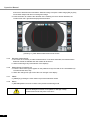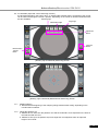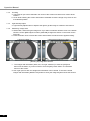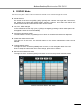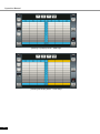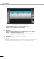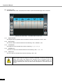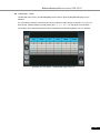
1
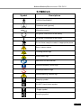
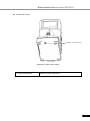
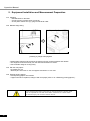
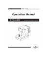
Autorefractor/Keratometer ERK-5400 IMPORTANT NOTICE [Classification under the provision of 93/42/EEC(MDD)] ClassⅡa The ERK-5400 is classified as Class Ⅱa device [Form of protection against electric shock] ClassⅠ The ERK-5400 is classified as Class I. This product is always protected when you connect the power supply must be connected to ground included. Class I is a product in which the protection against electric shock does not rely on basic insulation only, but which includes an additional safety precaution in such a way that means are provided for the connection of the product to the protective (ground) conductor in the fixed wiring of the installation in such a way that accessible metal parts cannot become live in the event of a failure in the basic insulation. Use a power outlet which is equipped with a grounding terminal. [Degree of protection against electric shock] Type B Applied Part The ERK-5400 is classified as a device with a Type B Applied Part [Degree of protection against ingress of liquids] IPX0 The ERK-5400 is classified as IPX0 [Degree of protection against flammability] The ERK-5400 is classified as a device not suitable to be used in a potentially flammable environment. Do not use near flammable materials [Method(s) of sterilization or disinfection recommended by the manufacturer] The forehead rest and chinrest should be wiped using a cloth dampened with soapy water as necessary [Mode of operation] Classification of ERK-5400 : continuous operation This product may malfunction due to electromagnetic waves caused by portable personal telephones, transceivers, radio-controlled toys, etc. Be sure to avoid having objects such as, which affect this product, brought near the product. It should be used under the supervision of medical staff of hospital The information in this publication has been carefully checked and is believed to be entirely accurate at the time of publication. ERK-5400 assumes no responsibility, however, for possible errors or omissions, or for any consequences resulting from the No use of the information contained herein. ERK-5400 reserves the right to make changes in its products or product specifications at any time and without prior notice, and is not required to update this documentation to reflect such changes. All rights reserved. Under copyright laws, this manual may not be copied, in whole or in part, without the prior written consent of ERK-5400 1 Operation Manual SAFETY INFORMATION Accessory equipment connected to the analog and digital interfaces must be certificated according to the respective IEC/EN standards (e.g. IEC/EN 60950 for data processing equipment and IEC/EN 60601-1 for medical equipment). Furthermore all configurations shall comply with the system standard EN 60601-1-2:2007. Everybody who connects additional equipment to the signal input part or signal output part configures a medical system, and is therefore responsible that the system complies with the requirements of the system standard EN 60601-1-1:2001. If in doubt, consult the technical service department or your local representative. For EU Countries The following mark, the name & address of the EU Representative shows compliance of the instrument with Directive Council Directive 93/42/EEC of 14 June 1993 as amended by Directive 2007/47/EC concerning medical devices. ISO 15004 This report provides information about the hazard to the examinee’s eyed in compliance with ISO 15004-1:2006, ISO 15004-2:2007 Ophthalmic instruments – Fundamental requirements and test methods Part2– Light hazard protection. This condition is satisfied even when the instrument is operating at maximum light intensity and maximum aperture! (Maximum intensity is the highest brightness the instrument is capable of delivering, including the highest brightness achievable if overvoltage is provided) detailed radiation information at normal usage of this instrument is like bellows. Radiation output: below 117.1 μW/cm2 Limit by ISO15004: 100 mW/cm2 Number Radiation output [μW/cm2] 1 2 3 4 5 6 7 8 9 10 107.0 117.1 115.5 115.7 103.6 103.7 108.8 109.0 105.6 105.8 average 109.1 0120 2 Autorefractor/Keratometer ERK-5400 SYMBOLS Symbol Descriptions TYPE B EQUIPMENT Protective earth (ground) Alternating current Off (power: disconnect to the mains) On (power: connection to the mains) Do not throw away the waste to inappropriate place Risk of electric shock Crushing hazard sign Hand hazard sign Instruction for user manual General mandatory action sign General prohibition sign General warning, caution sign Keep dry symbol DO NOT Hand Hooks symbol Fragile symbol Recycling symbol 3 Operation Manual Handle with care symbol This way up symbol Manufacture Europe Representative Manufacture Date Shape Of Plug Country Voltage/frequency Shape of plug Mexico 110V/50Hz Type C&E Argentina 220V/60Hz Type A Peru 220V/60Hz Type A Venezuela 110V/50Hz Type C&E Bolivia & Paraguay 220V/60Hz Chile 220V/60Hz Type A Colombia 110V/50Hz Type C 220V/60Hz Type A 127V/60Hz Type C Ecuador 110V/50Hz Type C&E USA 120V/60Hz Type A(Hospital Grade) Canada 120V/60Hz Type A(Hospital Grade) Brazil 4 Type A(Most common) Type H(Infrequently) Autorefractor/Keratometer ERK-5400 General Safety Information If you see any warnings or cautions printed on the warning labels, follow the safety instructions in this manual. Ignoring such cautions or warnings while handling the product may result in injury or accident. Be sure to read and fully understand the manual before using this product. Keep this manual in easy-to-access place. Safety Symbols and sign This indicates hazardous situations which may result in electrical shock to you. This indicates hazardous situations which may result in crush your hand. This indicates hazardous situations which may result insert your hand. This indicates hazardous situations which may result in minor injury to you or others, or may result in machine damage This indicates keep a mandatory action. if you do not action which could results in death or serious injury to you or others This indicates a infallible hazardous situation which could results in death or serious injury to you or others. NOTE This is used to emphasize essential information. Be sure to read this information to avoid incorrect operation. 5 Operation Manual INDEX IMPORATANT NOTICE ∙ ∙ ∙ ∙ ∙ ∙ ∙ ∙ ∙ ∙ ∙ ∙ ∙ ∙ ∙ ∙ ∙ ∙ ∙ ∙ ∙ ∙ ∙ ∙ ∙ ∙ ∙ ∙ ∙ ∙ ∙ ∙ ∙ ∙ ∙ ∙ ∙ ∙ ∙ ∙ ∙ ∙ ∙ ∙ ∙ ∙ ∙ ∙ ∙ ∙ ∙ ∙ ∙ ∙ ∙ ∙ ∙ ∙ 1 SAFETY INFORMATION ∙∙ ∙ ∙ ∙ ∙ ∙ ∙ ∙ ∙ ∙ ∙ ∙ ∙ ∙ ∙ ∙ ∙ ∙ ∙ ∙ ∙ ∙ ∙ ∙ ∙ ∙ ∙ ∙ ∙ ∙ ∙ ∙ ∙ ∙ ∙ ∙ ∙ ∙ ∙ ∙ ∙ ∙ ∙ ∙ ∙ ∙ ∙ ∙ ∙ ∙ ∙ ∙ ∙ ∙ ∙ ∙ ∙2 SYMBOLS∙∙ ∙ ∙ ∙ ∙ ∙ ∙ ∙ ∙ ∙ ∙ ∙ ∙ ∙ ∙ ∙ ∙ ∙ ∙ ∙ ∙ ∙ ∙ ∙ ∙ ∙ ∙ ∙ ∙ ∙ ∙ ∙ ∙ ∙ ∙ ∙ ∙ ∙ ∙ ∙ ∙ ∙ ∙ ∙ ∙ ∙ ∙ ∙ ∙ ∙ ∙ ∙ ∙ ∙ ∙ ∙ ∙3 SHAPE OF PLUG ∙ ∙ ∙ ∙ ∙ ∙ ∙ ∙ ∙ ∙ ∙ ∙ ∙ ∙ ∙ ∙ ∙ ∙ ∙ ∙ ∙ ∙ ∙ ∙ ∙ ∙ ∙ ∙ ∙ ∙ ∙ ∙ ∙ ∙ ∙ ∙ ∙ ∙ ∙ ∙ ∙ ∙ ∙ ∙ ∙ ∙ ∙ ∙ ∙ ∙ ∙ ∙ ∙ ∙ ∙ ∙4 GENERAL SAFETY INFORMATION ∙ ∙ ∙ ∙ ∙ ∙ ∙ ∙ ∙ ∙ ∙ ∙ ∙ ∙ ∙ ∙ ∙ ∙ ∙ ∙ ∙ ∙ ∙ ∙ ∙ ∙ ∙ ∙ ∙ ∙ ∙ ∙ ∙ ∙ ∙ ∙ ∙ ∙ ∙ ∙ ∙ ∙ ∙ ∙ ∙ ∙ ∙ ∙ ∙5 1. 2. 3. 4. Features ∙ ∙ ∙ ∙ ∙ ∙ ∙ ∙ ∙ ∙ ∙ ∙ ∙ ∙ ∙ ∙ ∙ ∙ ∙ ∙ ∙ ∙ ∙ ∙ ∙ ∙ ∙ ∙ ∙ ∙ ∙ ∙ ∙ ∙ ∙ ∙ ∙ ∙ ∙ ∙ ∙ ∙ ∙ ∙ ∙ ∙ ∙ ∙ ∙ ∙ ∙ ∙ ∙ ∙ ∙ ∙ ∙ ∙ ∙ ∙ ∙ ∙ ∙ 7 Notes for Using the Instrument ∙ ∙ ∙ ∙ ∙ ∙ ∙ ∙ ∙ ∙ ∙ ∙ ∙ ∙ ∙ ∙ ∙ ∙ ∙ ∙ ∙ ∙ ∙ ∙ ∙ ∙ ∙ ∙ ∙ ∙ ∙ ∙ ∙ ∙ ∙ ∙ ∙ ∙ ∙ ∙8 Prerequisites for safety∙ ∙ ∙ ∙ ∙ ∙ ∙ ∙ ∙ ∙ ∙ ∙ ∙ ∙ ∙ ∙ ∙ ∙ ∙ ∙ ∙ ∙ ∙ ∙ ∙ ∙ ∙ ∙ ∙ ∙ ∙ ∙ ∙ ∙ ∙ ∙ ∙ ∙ ∙ ∙10 Introduction ∙∙∙∙∙∙ ∙ ∙ ∙ ∙ ∙ ∙ ∙ ∙ ∙ ∙ ∙ ∙ ∙ ∙ ∙ ∙ ∙ ∙ ∙ ∙ ∙ ∙ ∙ ∙ ∙ ∙ ∙ ∙ ∙ ∙ ∙ ∙ ∙ ∙ ∙ ∙ ∙ ∙ ∙ ∙ ∙ ∙ ∙ ∙ ∙ ∙ ∙ ∙ ∙ ∙∙ ∙ ∙ ∙ ∙ ∙ ∙11 Front side of body ∙ ∙ ∙ ∙ ∙ ∙ ∙∙∙ ∙ ∙ ∙ ∙ ∙ ∙ ∙ ∙ ∙ ∙ ∙ ∙ ∙ ∙ ∙ ∙ ∙ ∙ ∙ ∙ ∙ ∙ ∙ ∙ ∙ ∙ ∙ ∙ ∙ ∙ ∙ ∙ ∙ ∙ ∙ ∙ ∙ ∙ ∙ ∙ ∙ 11 Back side of body ∙ ∙ ∙ ∙ ∙ ∙ ∙ ∙ ∙ ∙ ∙ ∙ ∙ ∙ ∙ ∙ ∙ ∙ ∙ ∙ ∙ ∙ ∙ ∙ ∙ ∙ ∙ ∙ ∙ ∙ ∙ ∙ ∙ ∙ ∙ ∙ ∙ ∙ ∙ ∙ ∙ ∙ ∙ ∙ ∙ ∙ ∙ ∙ 12 Bottom side of body ∙ ∙ ∙ ∙ ∙ ∙ ∙ ∙∙∙ ∙ ∙ ∙ ∙ ∙ ∙ ∙ ∙ ∙ ∙ ∙ ∙ ∙ ∙ ∙ ∙ ∙ ∙ ∙ ∙ ∙ ∙ ∙ ∙ ∙ ∙ ∙ ∙ ∙ ∙ ∙ ∙ ∙ ∙ ∙ ∙ ∙ ∙ ∙13 GUI(User Interface)∙ ∙ ∙ ∙ ∙ ∙ ∙ ∙ ∙ ∙ ∙ ∙ ∙ ∙ ∙ ∙ ∙ ∙ ∙ ∙ ∙ ∙ ∙ ∙ ∙ ∙ ∙ ∙ ∙ ∙ ∙ ∙ ∙ ∙ ∙ ∙ ∙ ∙ ∙ ∙ ∙ ∙ ∙ ∙ ∙ ∙14 5. Equipment Installation and Measurement Preparation ∙ ∙ ∙ ∙ ∙ ∙ ∙ ∙ ∙ ∙ ∙ ∙ ∙ ∙ ∙ ∙ ∙ 16 6. Simple Mode ∙ ∙ ∙ ∙ ∙ ∙ ∙ ∙ ∙ ∙ ∙ ∙ ∙ ∙ ∙ ∙ ∙ ∙ ∙ ∙ ∙ ∙ ∙ ∙ ∙ ∙ ∙ ∙ ∙ ∙ ∙ ∙ ∙ ∙ ∙ ∙ ∙ ∙ ∙ ∙ ∙ ∙ ∙ 17 7. Measurement Mode∙ ∙ ∙ ∙ ∙ ∙ ∙ ∙ ∙ ∙ ∙ ∙ ∙ ∙ ∙ ∙ ∙ ∙ ∙ ∙ ∙ ∙ ∙ ∙ ∙ ∙ ∙ ∙ ∙ ∙ ∙ ∙ ∙ ∙ ∙ ∙ ∙ ∙ ∙ ∙ ∙ ∙ ∙ 19 7.1 RK Mode ∙ ∙ ∙ ∙ ∙ ∙ ∙ ∙ ∙ ∙ ∙ ∙ ∙ ∙ ∙ ∙ ∙ ∙ ∙ ∙ ∙ ∙ ∙ ∙ ∙ ∙ ∙ ∙ ∙ ∙ ∙ ∙ ∙ ∙ ∙ ∙ ∙ ∙ ∙ ∙ ∙ ∙ ∙ ∙ ∙ ∙20 7.2 REF Mode ∙ ∙ ∙ ∙ ∙ ∙ ∙ ∙ ∙ ∙ ∙ ∙ ∙ ∙ ∙ ∙ ∙ ∙ ∙ ∙ ∙ ∙ ∙ ∙ ∙ ∙ ∙ ∙ ∙ ∙ ∙ ∙ ∙ ∙ ∙ ∙ ∙ ∙ ∙ ∙ ∙ ∙ ∙ ∙ ∙ ∙22 7.3 KER Mode ∙ ∙ ∙ ∙ ∙ ∙ ∙ ∙ ∙ ∙ ∙ ∙ ∙ ∙ ∙ ∙ ∙ ∙ ∙ ∙ ∙ ∙ ∙ ∙ ∙ ∙ ∙ ∙ ∙ ∙ ∙ ∙ ∙ ∙ ∙ ∙ ∙ ∙ ∙ ∙ ∙ ∙ ∙ ∙ ∙ ∙23 7.4 Practice through the Model Eye ∙ ∙ ∙ ∙ ∙ ∙ ∙ ∙ ∙ ∙ ∙ ∙ ∙ ∙ ∙ ∙ ∙ ∙ ∙ ∙ ∙ ∙ ∙ ∙ ∙ ∙ ∙ 24 7.5 CLBC Mode ∙ ∙ ∙ ∙ ∙ ∙ ∙ ∙ ∙ ∙ ∙ ∙ ∙ ∙ ∙ ∙ ∙ ∙ ∙ ∙ ∙ ∙ ∙ ∙ ∙ ∙ ∙ ∙ ∙ ∙ ∙ ∙ ∙ ∙ ∙ ∙ ∙ ∙ ∙ ∙ ∙ ∙ ∙ 25 7.6 SIZE Mode ∙ ∙ ∙ ∙ ∙ ∙ ∙ ∙ ∙ ∙ ∙ ∙ ∙ ∙ ∙ ∙ ∙ ∙ ∙ ∙ ∙ ∙ ∙ ∙ ∙ ∙ ∙ ∙ ∙ ∙ ∙ ∙ ∙ ∙ ∙ ∙ ∙ ∙ ∙ ∙ ∙ ∙ ∙ ∙ ∙ ∙ ∙ ∙ 27 7.7 ILLUM Mode ∙ ∙ ∙ ∙ ∙ ∙ ∙ ∙ ∙ ∙ ∙ ∙ ∙∙ ∙ ∙ ∙ ∙ ∙ ∙ ∙ ∙ ∙ ∙ ∙ ∙ ∙ ∙ ∙ ∙ ∙ ∙ ∙ ∙ ∙ ∙ ∙ ∙ ∙ ∙ ∙ ∙ ∙ ∙ ∙ ∙ ∙ ∙ ∙ 29 8. DISPLAY Mode ∙ ∙ ∙ ∙ ∙ ∙ ∙ ∙ ∙ ∙ ∙ ∙ ∙ ∙ ∙ ∙ ∙ ∙ ∙ ∙ ∙ ∙ ∙ ∙ ∙ ∙ ∙ ∙ ∙ ∙ ∙ ∙ ∙ ∙ ∙ ∙ ∙ ∙ ∙ ∙ ∙ ∙ ∙ 33 9. SETUP ∙ ∙ ∙ ∙ ∙ ∙ ∙ ∙ ∙ ∙ ∙ ∙ ∙ ∙ ∙ ∙ ∙ ∙ ∙ ∙ ∙ ∙ ∙ ∙ ∙ ∙ ∙ ∙ ∙ ∙ ∙ ∙ ∙ ∙ ∙ ∙ ∙ ∙ ∙ ∙ ∙ ∙ ∙ ∙ 35 9.1 DISPLAYSETUP PAGE ∙ ∙ ∙ ∙∙ ∙ ∙ ∙ ∙ ∙ ∙ ∙ ∙ ∙ ∙ ∙ ∙ ∙ ∙ ∙ ∙ ∙ ∙ ∙ ∙ ∙ ∙ ∙ ∙ ∙ ∙ ∙ ∙ ∙ ∙ ∙ ∙ ∙ ∙ ∙ ∙ ∙ ∙ ∙ ∙ ∙ 35 9.2 MEASURE PAGE ∙ ∙ ∙ ∙ ∙ ∙ ∙ ∙ ∙ ∙ ∙ ∙ ∙ ∙ ∙ ∙ ∙ ∙ ∙ ∙ ∙ ∙ ∙ ∙ ∙ ∙ ∙ ∙ ∙ ∙ ∙ ∙ ∙ ∙ ∙ ∙ ∙ ∙ ∙ ∙ ∙ ∙ ∙ ∙ 36 9.3 PRINT SETUP PAGE ∙ ∙ ∙ ∙ ∙∙ ∙ ∙ ∙ ∙ ∙ ∙ ∙ ∙ ∙ ∙ ∙ ∙ ∙ ∙ ∙ ∙ ∙ ∙ ∙ ∙ ∙ ∙ ∙ ∙ ∙ ∙ ∙ ∙ ∙ ∙ ∙ ∙ ∙ ∙ ∙ ∙ ∙ ∙ ∙ ∙ ∙ ∙ ∙ ∙ 37 9.4 SYSTEM PAGE ∙ ∙ ∙ ∙ ∙ ∙ ∙ ∙ ∙ ∙ ∙ ∙∙ ∙ ∙ ∙ ∙ ∙ ∙ ∙ ∙ ∙ ∙ ∙ ∙ ∙ ∙ ∙ ∙ ∙ ∙ ∙ ∙ ∙ ∙ ∙ ∙ ∙ ∙ ∙ ∙ ∙ ∙ ∙ ∙ 38 9.5 DATE&TIME PAGE ∙ ∙ ∙ ∙ ∙ ∙ ∙ ∙ ∙ ∙ ∙ ∙ ∙ ∙ ∙ ∙ ∙ ∙ ∙∙ ∙ ∙ ∙ ∙ ∙ ∙ ∙ ∙ ∙ ∙ ∙ ∙ ∙ ∙ ∙ ∙ ∙ ∙ ∙ ∙ ∙ ∙ ∙ ∙ ∙ ∙ ∙ ∙ ∙ 39 9.6 MESSAGE PAGE ∙ ∙ ∙ ∙ ∙ ∙ ∙ ∙ ∙ ∙ ∙∙ ∙ ∙ ∙ ∙ ∙ ∙ ∙ ∙ ∙ ∙ ∙ ∙ ∙ ∙ ∙ ∙ ∙ ∙ ∙ ∙ ∙ ∙ ∙ ∙ ∙ ∙ ∙ ∙ ∙ ∙ ∙ ∙ ∙ ∙ ∙ 40 10. Self Inspection and Maintenance ∙ ∙ ∙ ∙ ∙ ∙ ∙ ∙ ∙ ∙ ∙ ∙ ∙ ∙ ∙ ∙ ∙ ∙ ∙ ∙ ∙ ∙ ∙ ∙ ∙ ∙ ∙ ∙ ∙ ∙ ∙ ∙ ∙ ∙ ∙41 10.1 Before Calling a Service Person ∙ ∙ ∙ ∙ ∙ ∙ ∙ ∙ ∙ ∙ ∙ ∙ ∙ ∙ ∙ ∙ ∙ ∙ ∙ ∙ ∙ ∙ ∙ ∙ ∙ ∙ ∙ ∙ ∙ ∙ ∙ ∙ 41 10.2 Replacement of papers ∙ ∙ ∙ ∙ ∙ ∙ ∙ ∙ ∙ ∙ ∙ ∙ ∙ ∙ ∙ ∙ ∙ ∙ ∙ ∙ ∙ ∙ ∙ ∙ ∙ ∙ ∙ ∙ ∙ ∙ ∙ ∙ ∙ ∙ ∙ ∙ ∙ ∙ 42 10.3 Replacement of chinrest paper ∙ ∙ ∙ ∙ ∙ ∙ ∙ ∙ ∙ ∙ ∙ ∙ ∙ ∙ ∙ ∙ ∙ ∙ ∙ ∙ ∙ ∙ ∙ ∙ ∙ ∙ ∙ ∙ ∙ ∙ ∙ ∙ ∙ ∙ ∙ ∙ ∙ ∙ 42 10.4 When Moving the Instrument ∙ ∙ ∙ ∙ ∙ ∙ ∙ ∙ ∙ ∙ ∙ ∙ ∙ ∙ ∙ ∙ ∙ ∙ ∙ ∙ ∙ ∙ ∙ ∙ ∙ ∙ ∙ ∙ ∙ 42 10.5 Service Information ∙ ∙ ∙ ∙ ∙ ∙ ∙ ∙ ∙ ∙ ∙ ∙ ∙ ∙ ∙ ∙ ∙ ∙ ∙ ∙ ∙ ∙ ∙ ∙ ∙ ∙ ∙ ∙ ∙ ∙ ∙ ∙ ∙ ∙ ∙ ∙ ∙ ∙ ∙ ∙ 43 11. Specification ∙ ∙ ∙ ∙ ∙ ∙ ∙ ∙ ∙ ∙ ∙ ∙ ∙ ∙ ∙ ∙ ∙ ∙ ∙ ∙ ∙ ∙ ∙ ∙ ∙ ∙ ∙ ∙ ∙ ∙ ∙ ∙ ∙ ∙ ∙ ∙ ∙ ∙ ∙ ∙ ∙ ∙ ∙ ∙ ∙ ∙ ∙ ∙ ∙ 44 12. ACCESSARY ∙ ∙ ∙ ∙ ∙ ∙ ∙ ∙ ∙ ∙ ∙ ∙ ∙ ∙ ∙ ∙ ∙ ∙ ∙ ∙ ∙ ∙ ∙ ∙ ∙ ∙ ∙ ∙ ∙ ∙ ∙ ∙ ∙ ∙ ∙ ∙ ∙ ∙ ∙ ∙ ∙ ∙ ∙ ∙ ∙ ∙ ∙ ∙ 45 13. Packing∙ ∙ ∙ ∙ ∙ ∙ ∙ ∙ ∙ ∙ ∙ ∙ ∙ ∙ ∙ ∙ ∙ ∙ ∙ ∙ ∙ ∙ ∙ ∙ ∙ ∙ ∙ ∙ ∙ ∙ ∙ ∙ ∙ ∙ ∙ ∙ ∙ ∙ ∙ ∙ ∙ ∙ ∙ ∙ ∙ ∙ ∙ ∙ ∙ ∙46 14. EMC (ELECTROMAGNETIC COMPATIBILITY) ∙ ∙ ∙ ∙ ∙ ∙ ∙ ∙ ∙ ∙ ∙ ∙ ∙ ∙ ∙ ∙ ∙ ∙ ∙ ∙ ∙ ∙ ∙48 15. Disposal of waste products ∙ ∙ ∙ ∙ ∙ ∙ ∙ ∙ ∙ ∙ ∙ ∙ ∙ ∙ ∙ ∙ ∙ ∙ ∙ ∙ ∙ ∙ ∙ ∙ ∙ ∙ ∙ ∙ ∙ ∙ ∙ ∙ ∙ ∙ ∙ ∙ ∙ ∙52 4.1 4.2 4.3 4.4 6 Autorefractor/Keratometer ERK-5400 1. Features Intended Use The Auto Refractor/Keratometer ERK-5400 is used to determine the initial, objective refractive values for a patient’s eye in the workflow of refraction to determine the optical prescriptions for myopia, hyperopia and astigmatism. Various Measurements Supported Not only the usual refractometry and keratometry, but also corneal diameter and base curve of contact lens can be measured with this one instrument. Thus, measurements of eye and prescriptions for glasses and contact lenses can be made more efficiently. Wide Dioptric Measurement Range Because the ERK-5400 covers a wide measurement range, from -25D to +22D, even an examinee with strong myopia can be measured. More accurate Measurement The fogging method of the eye fixation target makes examinee’s eye comfortable and enables to get more accurate measurement data Simple and convenient user’s environment Deliver more convenient user environment with wide viewed 7.0 COLOR LCD screen and with simple and intimate design. Developed illumination May observe eye condition of the cataract or contact lens surface with this feature. May observe whenever it sis necessary since save up to 2 images of each eye. Easy Connection with other Equipment This instrument is designed to connect other Equipment such as LCD monitor. 7 Operation Manual 2. Notes for Using the Instrument 1. To avoid the risk of electric shock, this equipment as power protective earth connection must be connected 2. Ensure that the examinee has not placed his/her hand or fingers under the chin rest. Otherwise, hand or fingers may be hurt. 3. Do not hit or drop the instrument. The impact may cause damage to the function of this instrument. Please handle with care. 4. Only operate the instrument with the power supply indicated on the rating plate. Otherwise, it may result in fire or electric shock. 5. Never disassemble or modify. This can cause fire or electric shock. 6. In case there is smoke, strange odor or noise during operation, disconnect the power supply and consult the distributor. 7. For replacement parts (battery, fuse, or other parts), please contact the distributor from whom you purchased the product. 8. The external connection device is used UL certificate device and the specified power code, paper and fuse are used. 1. An exposure to the direct sunlight or too bright indoor lights may influence on the result of accurate measurement. Appropriate Optometry room use. 2. A sudden heating of the room in cold areas will cause condensation on the protective glass in the monitor screen and on optical parts inside the instrument. In this case, just wait until condensation disappears before performing measurement. 3. Keep the objective glass of the examinee side clean. If it was stained, it may cause on ERROR or inaccurate measurements. 4. If you leave ERK-5400 without using for certain period, disconnect the power supply and protect the unit with dust cover. 5. When moving this ERK-5400, fix the stage by using clamping bolt and stage holding knob, always keep power off, and then lift the bottom of the unit with both hands. 6. When moving this ERK-5400, do not hold forehead. 7. When moving and connect other device this ERK-5400, keep in touch with qualified technician or service agent and place the equipment plain. 8. Get worked, store and move under the following environment conditions for proper operation. 8 Autorefractor/Keratometer ERK-5400 -. Working condition : Temperature : +10℃ ~ +40℃ Humidity : 30% ~ 90% RH Atmospheric pressure range : 70 kPa ~ 106 kPa Shock (without packaging) : 10g / 6ms -. Storage and Moving condition : Temperature : -40℃ ~ +70℃ Humidity : 10% ~ 95% RH Atmospheric pressure range : 50 kPa ~ 106 kPa Shock : 30g / 6ms Permanent shock : 10g / 6ms Oscillate(sine curve) : 10Hz ~ 500Hz, 0.5g 9. Please use chin rest paper that is proven to be safe . 10. The patient should raise your hands in your lap when measuring 11. When S/W version up, check the label on the main board. 12. Optometry chamber is 55 ~ 100 [lux] illumination suitable. 1. Don’t use organic solvents such as alcohol, thinner, benzene, etc. to clean the surface of this instrument. It may damage the instrument. 2. Do not store alcohol, thinner and other flammable vapors and liquids in the vicinity of this equipment. 3. Do not turn off the instrument before finishing initialization. It may cause motor movement error. 4. Do not use outdoors. The instrument is designed to be used only indoors. 5. Do not use Humidity or dusty environment 6. Never disassemble or modify this instrument because it may result in fire or electric shock. Also, since this instrument incorporates high-voltage parts and other hazardous parts, touching them may cause death or serious injury. 7. Keep it away from other persons but qualified technician. 8. Be sure to turn OFF the power switch before connecting or disconnecting the cables. Also, do not handle them with wet hands. Otherwise, you may get an electric shock that may result in death or serious injury. 9. If you leave this instrument without using for certain period, disconnect the power supply 10. This equipment may be able to be operated improper by micro waves from cellular phones, walkie-talkie, remote controlled electric toys. Keep it away. . 9 Operation Manual 3. Prerequisites for safety 1) Preparation before use -. Do not operate under direct sunlight or too strong lights -. Do not store alcohol, thinner and other flammable vapors and liquids in the vicinity of this equipment. -. Check the voltage. -. Check printing papers are ready -. Check chin rest is working properly -. Remove dusts, especially on the lens. 2) Preparation when you use -. Place this equipment plain -. Do not put others on this equipment -. Do not disassemble or modify on your own -. Stand 40 minutes and get it worked if it is stored at extended temperate place -. Keep it away from other persons but qualified technician. -. Be sure to unplug if do not use long. -. Do not turn off the instrument before finishing initialization. (Don’t power off during loading) 3) Instruction and operation sequence -. Please connect the power plug. -. Press “ON” -. Put the chin on chin rest and make forehead stuck on to forehead rest -. Release stage by turning stage knob -. Press buttons what you want -. Try to get it worked as per the instructions of 4 and 5 4) Storing after use -. Cover it up and unplug if do not use long -. Clean with soft cloth, soaped and rinse, wipe dry -. Wipe lens and glass’ dusts out with wind blower and with soft cloth. -. Fix by turning the fixation knob and keep it plain when you are about to move or lift up -. Do store at the following place ① ② ③ ④ ⑤ ⑥ ⑦ Not humid place Not in the vicinity of water Not dusty and not in the vicinity of filthy place with salt or sulphur Plain place Not in the vicinity of vibration or shock Not in the vicinity of other flammables vapors or liquids Not in the vicinity of direct sunlight -. Store the accessories and cords for next operation. 10 Autorefractor/Keratometer ERK-5400 4. Introduction 4.1. Front side of body ① Touch screen Monitor ④ Height lining mark ② Measurement Button ⑤ Printer ⑥ Stage Holding Knob ③ Joystick [ Drawing 1] Front Side Name Functions ① Touch screen Monitor Monitor that displays Measurement ② Measurement Button Press this button for measurement. ③ Joystick Control lever for lining up and focusing ④ Height lining mark Lining up eye level of patient by regulating chin rest ⑤ Printer Print the measured result ⑥ Stage Holding Knob Holds the movement of stage [ Chart 1 ] Front side 11 Operation Manual 4.2. Back side of body ① Head Rest ⑤ Height lining mark ② Measurement window ③ Dust Cap ⑥ Power Switch ⑦ Fuse: TA2H 250V ④ Chin Rest ⑧ RS-232 Connector ⑫ Chin Rest ⑨ Power IN LET adjustment lever ⑩ EXT Video ⑪ USB Connector [Drawing 2 ] Back Side of Body Name Function ① Head Rest Place the examinee’s forehead against this rest. ② Measurement window Window for the examinee to look at for measurement ③ Dust Cap Anti-dust cap ④ Chin Rest Place the examinee’s chin on the rest. ⑤ Height lining mark Lining up eye level of patient by regulating chin rest ⑥ Power Switch Switch for turning power ON and OFF. ⑦ Fuse: TA2H 250V Protects instrument from the excess electric power. ⑧ RS-232 Connector Connect with PC ⑨ Power IN LET Connector for the power supply code ⑩ EXT Video Connect with external Video equipment ⑪ USB Connector Connect with PC ⑫ Chin Rest adjustment lever Regulating height of chin rest [Chart 2 ] Back side of body 12 Autorefractor/Keratometer ERK-5400 4.3. Bottom side of body ① Stage Clamping Bolt [Drawing 3 ] Bottom Side of Body ① Stage Clamping Bolt Makes the system stage fixed [Chart 3 ] Bottom Side of Body 13 Operation Manual 4.4. GUI(User Interface) The user interface was applied to the touch-screen buttons of the ERK-5400. So the user's convenience and speed of operation is improved. The frequently used buttons is located on the left and right of the screen frame. In the measurement mode is commonly used. The remaining modes except measurement modes each mode, please refer to the description page ⑮ Select Mode ①Serial Number ⓐPD ⑭ HOME Button ⓒCYL Pop-up Button ③ Right (Number) ⓗ Focus Bar ⓑVD ⓓSTEP ⑤ M Button ② Name ④ Left (Number) ⑤ Mode Button ⑥ Manual/Auto ⑧ DISPLAY Button Convert Button ⑦ IOL Button ⑨ SETUP Button ⑩ Prior Mode Select button ⑪ Next Mode Select button ⑫ Print ⑬ Clear button ⓕ Internal mark ⓖ Outside mark ⓔ Focus light mark [ Drawing 4 ] Touch Screen Name ① Serial Number The number of patients to be recorded on the printout. ② Name The patient's name is displayed and recorded on the printouts. Touch the name prompt will be executed. Top line represents the right eye being tested if patients is yellow marked otherwise black marked. The bottom row represents the number of measurements in each mode (RK-mode: REF / KER net). Top line represents the Left eye being tested if patients is yellow marked otherwise black marked. The bottom row represents the number of measurements in each mode (RK-mode: REF / KER net). Displays the Displays the current measurement mode. When the touch of a button pop-up button appears ⑮ mode selection can be changed to the desired measurement mode and automatically disappears after about 3 seconds ③ Right (Number) ④ Left (Number) ⑤ Mode Button 14 Function Autorefractor/Keratometer ERK-5400 ⑥ Manual/Auto Convert Button ⑦ IOL Button ⑧ Display Button ⑨ SETUP button ⑩ Prior Mode Select button ⑪ Next Mode Select button ⑫ Print ⑬ Clear button ⑭ HOME button ⑮ Select Mode Pop-up Button ⓐ PD ⓑ VD ⓒ CYL ⓓ STEP ⓔ Focus light mark ⓕ Internal mark ⓖ Outside mark ⓗ Focus bar The current measuring method indicates the manual( ) or the automatic( ) measurement. The touch of a button, you switch from manual to automatic or is opposed. In the bottom row left to automatically measure the number of measurements is displayed automatically. IOL represent the state and change. Run display Mode. Run the user setup mode. Inactive( ) / Active( ) Previous measurement mode is selected : REFKERRKCLBC Next measurement mode is selected : REFKERRKCLBC Print the result of Optometry. If you do not have an optometrist blank emissions results. Delete all optometrists results. Run the SIMPLE mode. The measurement mode is selected to run. Display of PD(Pupil Distance) results. Display of VD(Vertex Distance) results. When inactive, the touch screen entries and values VD. When you touch active in the VD is inactive. When you touch the value of the following values change: 0.010.012.013.515.0 Display of (Cylinder) results. When inactive, the touch screen entries and values CYL. When you touch active in the CYL is inactive. When you touch the value of the following values change: (-++-) Display of STEP value. When inactive, the touch screen entries and values STEP. When you touch active in the STEP is inactive. When you touch the value of the following values change: 0.250.12 Aim the target position of light. Aim for measuring light is located on the inside of the mark is then measured The target position. Depending on the size of the patient represents a different size. Depending on the size of It’s internal and external sight aiming mark the measurements performed on well-timed to mark. Indicates the focus state. If focus is a good fit, show as a single bar. The camera does not focus on the middle of the bar indicated by two broken. [Chart 4 ] Operation Button 15 Operation Manual 5. Equipment Installation and Measurement Preparation 5.1. Plugging - Put ERK-5400 on the table - Connect power cord into power connector - Check power switch OFF (O), plug into electrical outlet 5.2. Release stage fixing [ Drawing 5 ] Stage Clamping Bolt - Rotate stage clamping bolt located in the bottom of body counterclockwise and release - The stage fix knob of front body turn the UNLOCK direction for loosen. - Check whether stage is moving freely. 5.3. Slit chin rest papers - Pick both pins out. - Slit both pins into holes on chin rest papers and stick it on chin rest. 5.4. Engage printing papers - Check printing papers are inserted. - If paper need to be replaced, change it with new paper (refer to ‘10.2 Switching printing papers’ ). Turn off the power after connecting or disconnecting the power cable. Do not operate the unit with wet hands. Otherwise, to cause death or serious injury can result in electric shock. 16 Autorefractor/Keratometer ERK-5400 6. Simple Mode The simplex mode on the screen ERK-5400 offers a variety of features that are gathered. Touch a desired function can be executed immediately. The simple mode 'User Setup-SYSTEM page-SIMPLE MODE' action if the item is set to ON, then run automatically, and the upper-right corner of the screen of measurement mode [HOME] button to run the touch can do. [ Drawing 6] Simple Mode Screen 6.1. [INFOR] Touch Button It is show that important information about products. To return to the previous screen when you touch the window below is information. [ Drawing 7] Information Window 6.2. [SLEEP] Touch Button If you do not use standby mode by pressing this button can be forced to run. If you want to exit the standby mode, you can touch monitor or sleep button. User Setup-SYSTEM Page of the SCREEN OFF does not affect entry. If the value of this item is set to OFF, press this button in standby mode is executed. 6.3. [NAME] Touch Button The patient's name can be enter to a maximum of 16. The patient's name on the top right corner of the screen scrolls are displayed. The patient's name will be printed when you print. 17 Operation Manual Name Edit Window Cursor Button A/a Switch Button [ Drawing 8] Enter Name Screen [ Character Input ] To enter characters by tapping the button that corresponds to a maximum of 16 characters, you can type a letter. Entered the name of the character being added to the edit window of the red cursor to move the cursor one space to the right. After entering all 16 characters, the computer emits a beep and does not enter any more characters [Character Delete] Using touch-button ([]) to delete characters when you press and hold the information entered is all deleted. [Return to the prior screen] [YES] button to save the name and touch to return to the previous screen. [NO] button is pressed, touch the name to return to the previous screen without saving. 6.4. [REF]/[KER]/[RK]/[CLBC]/[SIZE]/[ILLUM] Touch Button Touch the button that corresponds to the measurement and test run mode 6.5. [DISP] Touch Button Run display Mode 6.6. [RESET] Touch Button Without using the power switch to reboot system.. 6.7. [SETUP] Touch Button Run SETUP Mode 6.8. [PRINT] Touch Button The measured results are printed. If measured results not exist it is ejected blank paper. The prior measurements mode or the REF mode to run. 6.9. [CLEAR] Touch Button The measured results are deleted. The prior measurements mode or the REF mode to run. 6.10. [MEASUREMENT MODE] Touch Button & [EXIT] Touch Button The prior measurements mode or the REF mode to run 18 Autorefractor/Keratometer ERK-5400 7. Measurement Mode The main function of ERK-5400 is refractive, keratometry measurement, keratometry/refraction continuous measurement and base curve measurement of contact lens. After enough practice, through model-eye( chapter 7.4) patients should be measured. [Changing the measurement mode] The screen left / right in the [MODE] button to touch activated POP-UP window you can select the desired mode. The POP-UP window automatically disappears about 3 seconds. The screen left / right in [triangle arrow] button to touch you can select the previous or next mode. In the upper right corner of the screen [HOME] button to run the simple mode and simple mode you can select the desired measurement mode. [Measurement start mode] Manual measurement mode The Common measurement methods measure the operator to push the button the measurement will start. Auto measurement mode Operator do not need to press the measure button is focused to the center and automatically starts measuring. Measurements in the automatic measurement mode by pressing the button will start the measurement. To change the auto measurement mode, the left side of the screen, the [MANU] a touch of the button or press the MEASURE page User Setup system on the AUTO START and AUTO or AUTO-P can be chosen. [MANU] Touch the button [AUTO] AUTO-touch buttons and text changes to remaining Number will be displayed below. Measurement of the MEASURE page number in the User Setup AUTO REPEAT is the value of the item you want, change the value. < Manual Measurement Mode > < Auto Measurement Mode > [ IOL Measurement mode ] Intraocular lens (IOL) or cataract surgery patients as a measure of patients are turbid lens [IOL] touch button, please press the measure. REF mode or RK-mode measurement modes are supported on the IOL. IOL measurement mode is active or inactive on the left of the screen, the button can be confirmed by an IOL. < Inactive IOL> < Active IOL > Iris has damaged on Some of IOL patient. If damage is deep, measurement result may have some error. 19 Operation Manual 7.1. RK Mode (keratometry/refraction continuous measurement mode) RK mode with corneal radius and refraction can be measured. Ring Optical aiming [ Drawing 9 ] RK Mode Screen 20 7.1.1. Select RK mode a. Described at the beginning of this chapter [The Change of measurement mode] how to select the RK mode by referring. 7.1.2. Adjust the patient's eye a. Patients sit in a chair, then the patient's chin and the forehead is to be expected on the base of the forehead and chin rest. b. Patients to face up to the patient's eye level height chin rest alignment mark to adjust the height of chin rest fit. 7.1.3. Focus a. Push the lever to the left of the screen to appear on the patient's right eye aligned. b. Central target for patients to balloon to see the red part of the request. c. If the ring is on the screen obscured by eyelids, subjects with eyes wide open until the end of the measurement is requested. d. Looking at the screen ring internal / external aiming at the mark to adjust the lever to position. If the ring is located near the center of the screen near the Focus light mark Optical aiming (bright spot) will appear. Focus light mark on optical aiming to position the lever in the left / right tilt with the return or adjustment. Lever forward / backward moving the focus ring to sharpen. Focus bar located above the focus, if correct, is represented by one bar. 7.1.4. Measurement a. Touch measurement button. b. Upon completion of measurements at the bottom left of the screen is displayed and the bottom right of REF measurement results are displayed in the KER measurement. If the measurement is not normally a "RETRY" or "AGAIN" will be displayed. c. Depending on user setup system selected in the VD, CYL, and the display format can be changed. 7.1.5. Repeated measurements a. Repeated measurements are necessary. b. When measuring every last measure of the displays Autorefractor/Keratometer ERK-5400 Measurement of opposite eye a. Push the lever to the right to appear on the patient's left eye focused on the contralateral eye is measured the same way. b. When the change left, right / left of the icon changes color display. Depending on the icon of the left eye and right eye measurement results are displayed. c. Both left and right eye when measured PD values are displayed on the screen. 7.1.6. PRINT a. [PRINT] by pressing the touch button to print the measured results. b. Depending on the user setup mode is selected in different prints.. < Print Mode – IMG > < Print Mode – ALL > Name Recognizing the name, enter the name is not printed if it is not. # Indication The focus does not fit the measured values are displayed in the state. [I] Indication The patients with IOL (intraocular lens), as measured by the value of mode is displayed [ Drawing 10 ] Print Sample Do not place hand or fingers under the chin rest. This could result in damage or injury. Pull the refractometer away from the patient when moving right or left, otherwise the face could be injured. Keep the objective glass on the examinee side clean. If it is smudged, it may cause inaccurate measurements. 21 Operation Manual 7.2. REF mode (Refraction measurement mode) REF mode can be used to measure the refraction. REF measured in the same way as the RK-mode measurements. [ Drawing 11 ] REF Mode Screen 22 7.2.1. Select REF Mode a. Described at the beginning of this chapter [Change measurement mode] Note how the REF mode. 7.2.2. Adjust the patient's eye: the operation is in Section 7.1.2. 7.2.3. Focus: Section 7.1.3 is the operation. 7.2.4. Measurement a. Measurement button. b. Upon completion of measurements at the bottom left of the screen displays the measurement results REF. If the measurement is not normally a "RETRY" or "AGAIN" will be displayed. c. Depending on user setup system selected in the VD, CYL, and the display format can be changed. 7.2.5. Repeated measures: Section 7.1.5 is the operation. 7.2.6. Opposite eye measurement: is the operation section 7.1.6. 7.2.7. Printed in section 7.1.7 to the operation. Autorefractor/Keratometer ERK-5400 7.3. KER Mode (Keratometry measurement mode) KER mode can be used to measure corneal radius. KER measured in the same way as the RK-mode measurements. [ Drawing 12 ] KER Mode Screen 7.3.1. Select KER mode a. Described at the beginning of this chapter [Change measurement mode] Note how the KER mode. 7.3.2. Adjust the patient's eye: the operation is in Section 7.1.2. 7.3.3. Focus: Section 7.1.3 is the operation. 7.3.4. Measurement a. Measurement button. b. Upon completion of measurements at the bottom left of the screen displays the measurement results KER. If the measurement is not normally a "RETRY" or "AGAIN" will be displayed. 7.3.5. Repeated measures: Section 7.1.5 is the operation. 7.3.6. Opposite eye measurement: is the operation section 7.1.6. 7.3.7. Printed in section 7.1.7 to the operation 23 Operation Manual 7.4. Practice through the Model Eye Before measuring patients in the product, measured by using a model that should please plenty of practice. 7.4.1. Power ON a. Located in the lower-right corner of the body and turn on the power switch. 7.4.2. Installation a. Remove the chin rest paper and model eye pin and the pin plug to snap. [ Drawing 13 ] Model Eye 7.4.3. Release unlock Stage a. Rotate stage clamping bolt located in the bottom of body counterclockwise and release. b. The stage fix knob of front body turn the UNLOCK direction for loosen. 7.4.4. Select RK mode or REF mode a. Described at the beginning of this chapter, a measurement mode change] See how the RK or REF mode. 7.4.5. Model eye position and focusing. Turn the lever while watching the screen model eye is aligned with the height of the measurement window. Internal mark until near the optical aiming to adjust the lever. Adjustment lever left or right turn or two internal mark the center of the optical aiming to fit to fit. Move the lever forward and back focus ring to sharpen the image. 7.4.6. Measurement Described at the beginning of this chapter [measurement start mode], depending on the manual/auto is the measurement. Keep the objective glass of the examinee side clean. If it was stained, it may cause on ERROR or inaccurate measurements. 24 Autorefractor/Keratometer ERK-5400 7.5. CLBC Mode (base curves of contact lens) Measure base curves of contact lens in CLBC mode. 7.5.1. Attach contact lens a. Load lens up after dampen convex part of model eye, back side.be careful lens. Contact Lens [ Drawing 14 ] Attachment Contact Lens 7.5.2. Select CLBC Mode a. Described at the beginning of this chapter [change measurement mode], depending on the CLBC mode is selected. [Drawing 15 ] CLCB Mode Screen 7.5.3. Load model eye a. Get rid of chin rest paper and pick fixing pins and pick model eye into fixing pins 25 Operation Manual 7.5.4. Position and Focus a. Ring image by looking at the screen ring internal / outside mark located near the lever to adjust. b. Ring in the center of the screen when you close Focus light mark will appear near the aiming mark. Focus light mark the aiming mark to position the lever in the left / right or forward / back, move or adjust. c. Lever and forward / back, move the ring to sharpen focus. Focus bar in one focus, if correct, will be displayed. 7.5.5. Measurement a. Measurement button. b. Upon completion of measurements at the bottom left of the screen displays the measurement results. If the measurement is not normally a "RETRY" or "AGAIN" will be displayed. 7.5.6. Repeated measurements a. Repeated measurements are necessary. b. When measuring every last measure of the displays 7.5.7. PRINT a. [PRINT] by pressing the touch button to print the measured results. b. Depending on the user setup system mode is selected in different prints. Keep the objective glass of the examinee side clean. If it was stained, it may cause on ERROR or inaccurate measurements. NOTE 26 After printing, the previous results will be automatically removed when the next measurement. Prints recorded by the heat, so when you need long-term storage is recommended that you make a copy and drop. Autorefractor/Keratometer ERK-5400 7.6. SIZE Mode (Diameter measurement mode) SIZE mode can be used to measure the diameter of the cornea. Left / Right eye values for the two results can be saved. The measurement of corneal diameter appears on the screen focuses on the patient's eyes are the clearest measure is obtained by pressing the stationary image. The stationary image that you want to measure the diameter of the left and right on target and locate two of the bar diameter can be measured. Diameter Left bar Scale Right bar Right bar moving touch button Left bar moving touch button Left bar moving range Right bar moving range [Drawing 16 ] SIZE Mode Screen 7.6.1. Select mode a. Described at the beginning of this chapter [change measurement mode], depending on the SIZE mode is selected. 7.6.2. Adjust the patient's eye a. Patients sit in a chair, then the patient's chin and the forehead is to be expected on the base of the forehead and chin rest. b. Patients to face up to the patient's eye level height chin rest alignment mark to adjust the height of chin rest fit. 7.6.3. Focusing a. The image of eye to be measured in the center of the screen so that the lever used to fit the location. b. Lever while watching the screen and forward / backward moves the image of eye focus on the most brilliant position. 7.6.4. Measurement a. Press the button to measure the stationary image is acquired. b. Measurements of the subjects to the left / right when you are away from the boundary and the boundary with the bar near the bar to touch the places near the border. c. [Left / Right bar Go button to touch the left / right on the border of the bar and place to be measured. If it is difficult to identify the boundaries [Zx2] or [Zx3] button to enlarge the image 27 Operation Manual and touch to determine the boundaries. Without having to acquire a static image [Zx2] or [Zx3] touch button beeps and does not enlarge the image. d. Press the button to measure the diameter of the resulting current is stored. Diameter, the results screen left / right will be displayed at the bottom. [Drawing 17 ] SIZE Mode measurement result screen 7.6.5. Repeated measurement a. Two times as necessary to make measurements. Three times thereafter, first measured the diameter results are deleted and new results will be stored. b. When measuring every last measure of the displays. 7.6.6. Measurement of opposite eye a. Push the lever to the right to appear on the patient's left eye focused on the contralateral eye is measured the same way. b. When the change left, right / left of the icon changes color display 7.6.7. PRINT a. [PRINT] by pressing the touch button to print the measured results. 7.6.8. Return a. [RETURN] button to touch to return to the previous measuring mode. Iris has damaged on Some of IOL patient. If damage is deep, measurement result may have some error. 28 Autorefractor/Keratometer ERK-5400 7.7. ILLUM Mode (Pupil and cornea observing function) ILLUM mode with light in the pupil or lens, or cataract state whether there is scratching of the cornea can be observed through the screen. operator, depending on the needs of refraction measurements are also available. Observing light illumination light Target light Adjustment Button Image list Button Measurement/ Transfer Button [Drawing 18] ILLUM Mode (Observing) Screen [Drawing 19] ILLUM Mode (Measurement/ Observing) Screen 7.7.1. MODE selection a. Described at the beginning of this chapter [change measurement mode], depending on the ILLUM mode is selected. 7.7.2. Adjust the patient's eye a. Patients sit in a chair, then the patient's chin and the forehead is to be expected on the base of the forehead and chin rest. b. Patients to face up to the patient's eye level height chin rest alignment mark to adjust the height of chin rest fit. 29 Operation Manual 7.7.3. Focusing a. The image of eye to be measured in the center of the screen so that the lever used to fit the location. b. Lever while watching the screen and forward / backward moves the image of eye focus on the most brilliant position. 7.7.4. Light intensity adjust a. Light intensity adjust button to adjust to the light to get the image to create an environment. 7.7.5. Observing / Image save a. Observation, while saving the image even if you want to measure refractive error in the bottom left of the screen [MSR off] touch button. [MSR ON] changes are shown on the screen as the focus bar. b. Press the button once to freeze the screen and measure the stored screen appears asking. < Observing Mode > < Measurement/Observing Mode > [Drawing 20] Image Save Screen c. . The Images and information (date, time, VD, light, refraction) to save the [YES] and then touch the button, if you do not want to save the [NO] a touch button. ILLUM mode returns to the screen. d. Left / right eyes for each two images and information can be stored. To check the stored images and information [IMAGE LIST] button to touch [the image list] will execute the function. 30 Autorefractor/Keratometer ERK-5400 7.7.6. Comparison of images through image list List screen image left / right eye and stored in a recent left / right eye images for each one (half size, total 2), and the whole image (quarter size, total 4) and shows all on one screen. The selected image is displayed outside the blue box. The half of the images for the selected image displayed on the top of the screen shows the information. a. Comparison of quarter-size images are observed. b. Touch the image you want to observe in detail. The half size of the image is changed, and information about the image appears at the top of the screen. c. If you want to observe the original size [VIEW] button to touch [image] function executed. d. If you want to go back to previous ILLUM mode [RETURN] button touch. [Drawing 21] Image List Screen 31 Operation Manual 7.7.7. The observing original image through Image view The Image view Screen is displayed for the original size image and image information. a. Eye through the image of the original size to observe the state. b. If you want to go back to the image list screen [IMAGE LIST] touch button. c. If you want to go back to previous ILLUM mode [RETURN] button touch [Drawing 22] Image View Screen 7.7.8. 32 Return to the measurement mode. ILLUM mode [RETURN] button to touch to return to the previous measuring mode. Autorefractor/Keratometer ERK-5400 8. DISPLAY Mode Measured on the screen [DISP] button touch display mode is executed. Display mode stored in the internal memory REF / KER / CLBC measurement results can be verified through the screen. 8.1. Mode Selection On the left side of the screen [REF] / [KER] / [CLBC] touch a button or the right side of the screen, the [DISP] touch buttons (REFKERCLBC sequential change), press select and change the measurement mode and measurement results can be checked . 8.2. VD, CYL, STEP changes In the center of the screen [VD] / [CYL] / [STEP] is changed by pressing the touch button option can be applied to check the result immediately. 8.3. Print the measurement results The left side of the screen, the [PRINT] button to touch the measurement results can be printed. 8.4. Delete the measurement results The right side of the screen, the [CLEAR] button to touch all the measurement results can be deleted. 8.5. Change the user name The right side of the screen, the [NAME] button to touch you can change the name of the user. How to change the name of the user's name change, please refer to the user. 8.6. Back to the measurement mode. The right side of the screen, the [EXIT] touch button to return to the previous measuring mode. [Drawing 23] Display Mode – REF Page 33 Operation Manual [Drawing 24] Display Mode – KER Page [Drawing 25] Display Mode – CLBC Page 34 Autorefractor/Keratometer ERK-5400 9. SETUP Measurement screen from [SETUP] touch button, you push the User setup mode is executed. User setup mode the DISPLAY, MEASURE, PRINT, SYSTEM, DATE & TIME page footers, and print settings are configured. [ Select page ] Screen left / right of the [DISP] / [MEASURE] / [PRINT] / [SYS] / [DATE & TIME] touch button or the [SETUP] touch button (DISPLAY MEASURE PRINT SYSTEM DATE & TIME sequential change) and push the page on you can select or change. [Setup the print footer] The [MSG] touch button on the left side of screen push print footer editing the footer can be set . [Recalling a preset value] The right side of the screen, the [CLEAR] and press the touch prior can bring up the settings. [Return the measurement mode] The right side of the screen, the [EXIT] touch button to return to the previous measurement mode. 9.1. DISPLAY SETUP PAGE The right side of the screen, the [DISP] touch button to push the DISPLAY page, you can choose. [Drawing 26 ] User Setup – DISPLAY Page List 9.1.1. STEP The refraction units of measurement results select from the following : '0 .25 ', '0 .12'. 9.1.2. CYL FORM The Astigmatism (Cylinder) sign of measurement result select from the following : '-', '+' and '+ -'. 9.1.3. Vertex Distance The Vertex Distance select from the following : ‘0.0’, ‘10.0’, ‘12.0’, ‘13.5’, ‘15.0’ 9.1.4. KERATO FORMAT The Unit of KERATO measurement result select from the following : ‘RADIUS’, ‘DIOPT’. ▪ RADIUS : mm unit ▪ DIOPT : D unit 9.1.5. PREVIEW The preview of measurement results before printing select from the following : ‘OFF’, ‘ON’. 35 Operation Manual 9.2. MEASURE PAGE The [MEASURE] touch button of left side of the screen, you can select the push MEASURE page. [Drawing 27] User setup – MEASURE Page List 9.2.1. SHOOTING MODE The measurement method select from the following: ‘NORMAL’, ‘FAST’ ▪ NORMAL : One measurement and one result is obtained. ▪ FAST-3 : Three measurements and three results are obtained. ▪ FAST-5 : Five measurements and five results are obtained. 9.2.2. AUTO START The AUTO measurement method select from the following: ‘MANUAL’, ‘AUTO’,’AUTO-P’ ▪ MANUAL : It is measured via the measurement button. ▪ AUTO : It is measured automatically. ▪ AUTO-P : Automatic measurement mode for measuring and binocular measurement is complete, the results will print automatically. 9.2.3. AUTO REPEAT The automatic measurement number select from the following: ‘1’, ‘3’, ‘5’, ‘7’ 9.2.4. SPH SHIFT The spherical value is calibrated. The sign of '-' to reduce the number of the corrections 0.125D, for the correction increases the number of 0.125D and '0 .0 ' as the 0.0D is corrected. 36 '+' Autorefractor/Keratometer ERK-5400 9.3. PRINT SETUP PAGE The left side of the screen, the [PRINT] touch button to push the PRINT page can be selected. [Drawing 28] User Setup – PRINT Page Value List 9.3.1. PRINT TYPE The type of print is selected select from the following: ‘ALL’, ‘IMG’, ‘AVR’, ‘OFF’ ▪ ALL : All individual values and averages of the results is printed. ▪ IMG : The IMAGE of refraction data and the average of measurement results are printed. ▪ AVE : The average of measurement results are printed. ▪ OFF : The measurement results does not printed. 9.3.2. PRINT NO. The number of print whether or not to print ON ',' OFF 'to select. The choose to RESET is the number of print to zero. 9.3.3. DATE FORMAT The format of date is selected select from the following: ‘YMD’, ‘DMY’, ‘MDY’ ▪ YMD : Year-month-day order is displayed. ▪ DMY : Day-month-year order is display. ▪ MDY : Month-day-year order is display. 9.3.4. 24H MODE Display of hour selected select from the following: ‘12H’, ‘24H’ 37 Operation Manual 9.4. SYSTEM PAGE The left side of the screen, the [SYS] touch button to push the SYSTEM page can be selected. [Drawing 29 ] User Setup – SYSTEM PAGE VALUE LIST 9.4.1. SIMPLE MODE The simple mode of operation when the behavior whether the selection of 'OFF', 'ON' . 9.4.2. KEY SOUND The sound of KEY is selected select from the following: ‘OFF’, ‘MIDDLE’, ‘ON’ 9.4.3. LCD BRIGHT The bright of LCD is selected select from the following: ‘1’, ‘2’, ‘3’, ‘4’, ‘5’ 9.4.4. SCREEN OFF The time of screen off is selected select from the following: ‘OFF’, ‘3’, ‘5’, ‘10’. 9.4.5. VIDEO OUT The out of video is selected select from the following: ‘OFF’, ‘ON. External video output to support a resolution of 800x480. To view an external video output VGA monitor that supports this resolution must be prepared. Does not support this resolution, the screen of your monitor may not display properly. For questions regarding the monitor and the monitor manufacturer or the seller, ask the monitor. 38 Autorefractor/Keratometer ERK-5400 9.5. DATE&TIME PAGE The left side of the screen, the [DATE&TIME] touch button to push the DATE&TIME page can be selected. You can change increase or decrease the current value that Years (00-99), month (01-11), a (01-31), time (00-23), minutes (00-59), second (00-59) and '-1', '+1 ',' -10 ',' +10' with push to touch button . The Change of the date and time takes effect immediately and stored separately, are not checked. [Drawing 30 ] User Setup – DATE&TIME Page Value List 39 Operation Manual 9.6. MESSAGE PAGE The left side of the screen, the [MSG] touch button can be edited by pressing the print footer and a total of 44 characters (22 characters per line, 2 line x) can be entered. Cursor [Drawing 31] Editing Screen Printing Footer [ CARACTER INPUT ] Enter the characters you can type the characters touch. The message window is added to the red under the red cursor to the cursor position when you type a character to move one step to the right. After you enter all 44 characters, the computer emits a beep and does not enter any more characters. [ DELETE THE CHARACTER] [] using touch button can delete a character. Press and hold the entries are deleted. [ SAVE THE CONTENTS ] The [SAVE] touch button you push to temporarily store the edited print footer. The Left / Right edited by pressing the other touch button to print footers will not be saved temporarily. ※ The part of the current page is stored in the User Setup temporarily stored state to be shut down when saving an edited print footers will be printed when printing. 9.7. CODE The code is a feature for Servicemen, operation manual does not describe. 40 Autorefractor/Keratometer ERK-5400 10. Self Inspection and Maintenance 10.1. Before Calling a Service Person Warning messages will be displayed on the monitor if some problems occur. It might be operation errors or problems of the machine. In this case, refer the following instructions. If the function is still not salvaged or recovered, disconnect the power supply and consult the dealer. (1) Message When Power On Message Cause FOG MOTOR FAIL Internal error SHUT MOTOR FAIL Remedy Turn OFF the power switch and turn on again after 10 seconds. If the message appears again, consult the dealer. (2) Message On Measuring Message RETRY Cause Remedy Alignment is improper Measure after aligning the pupil and the Alignment Mark properly. Eyelid or eyelashes are covering the pupil. Instruct the examinee to open his or her eyes wide, or lift up the eyelid lightly with your fingers and measure again When the pupil is smaller than the Outer Alignment Mark. The minimum pupil diameter that can be measured is 2.0 mm. Although it is possible to measure in the bright place, don’t expose examinee’s eyes to the direct sunlight or too bright indoor lights to prevent the contraction of the pupil. When the examinee has some illness like cataract. Observe the eye in SIZE Mode. If cataract is not severe, measurement can be performed in the IOL mode. Examinee has IOL (intraocular lens) implanted. Measure in the IOL mode. When the Mire Image is odd shaped because of tears. When the Mire Image is not clear Instruct the examinee to open and close his or her eyes several times and measure again. because the cornea is dry. Examinee has strong irregular Impossible to measure astigmatism or corneal disease. AGAGIN OUT+ OUT- Measurement result is not reliable. Measure again. Data was out of valid Measurement result is unreliable. Please measurement range. measure again. 41 Operation Manual 10.2. Replacement of papers If red line is printed on paper, please replace printer paper with new one. Insert position [Drawing 32 ] Replacement of printer paper a. Open the printer cover and push the handle and then pull out the printer. b. Put the end of printer paper on insert position (refer to picture 32), and then push it up softly. Then paper will be inserted automatically c. Insert the end of paper (which comes out from printer) into paper hole on printer cover. And then close printer cover ** If paper was not inserted enoughly, pull it by hand. ** Please check paper type and size. (Paper type: Thermal Paper, Size: Width 57mm / External diameter 50mm) 10.3. Replacement of chinrest paper a. Pull out 2 holding pins on chinrest. b. Insert holding pins into the hole on chinrest paper. ( more than 50pcs available ) c. Insert 2 holding pins into the hole on chinrest. 10.4. When Moving the Instrument a. Turn OFF the power switch. b. Disconnect the power cable c. Close the stage holding dial in the clockwise direction d. Move this machine holding the lower part of the mains to keep horizontally. 42 Autorefractor/Keratometer ERK-5400 10.5. Service Information (1) Repair If problem cannot be solved even after taking the measures indicated in section 10.1, contact ERK-5400 representative or distributor for repair. Please refer to the name plate and let us have the following information: ▪ Name of the instrument : ERK-5400 ▪ Serial Number : 7-digit characters indicated on the name plate ▪ Phenomenon : In detail ▪ Size : 79(W) x 31(D) mm (2) Limit for Supplying Performance Parts for Repair Performance part (required to maintain the functioning of the product) of this product will be stocked for six years after discontinuation of product, to allow for repair 43 Operation Manual 11. Specifications Refractometry Vertex Distance(VD) 0.0 , 10.0, 12.0, 13.5, 15.0mm Sphere(SPH) -25.00 ~ +22D (VD 12mm) Cylinder(CYL) 0.00~±10.00D Axis(AX) 1~180˚ Cylinder form -, +, Mix Pupil Distance(PD) 10~85mm Minimum Pupil Diameter Ø2.0mm Unit : 0.12 / 0.25 D Unit : 0.12 / 0.25 D Unit : 1˚ Keratometry Radius of Curvature 5.0~10.2mm Unit : 0.01mm Corneal Power 33.00~67.50D Unit : 0.12/ 0.25 D Corneal Astigmatism 0.00~-15.00D Unit : 0.12/ 0.25 D 1~180˚ Axis Unit : 1˚ Corneal Diameter Corneal Diameter 2.0~12.00mm Unit : 0.1mm ETC. 44 Storage Memory 10 measurement each eyes Internal Printer Thermal printer Display 7.0 inch LED Monitor Thin rest movement Manual Operation environment Temperature : +10℃ ~ +40℃ Humidity : 30% ~ 90% RH Atmospheric pressure range : 70 kPa ~ 106 kPa Shock (without packaging) : 10g / 6ms Storage and Movement environment Temperature : -40℃ ~ +70℃ Humidity : 10% ~ 95% RH Atmospheric pressure range : 50 kPa ~ 106 kPa Shock : 30g / 6ms Permanent shock : 10g / 6ms Oscillate(sine curve) : 10Hz ~ 500Hz, 0.5g Power supply AC100V ~ 240V.50/60Hz Power consumption 90VA Dimension 248mm(W) x 476mm(D) x 475mm(H) Weight 21kg Autorefractor/Keratometer ERK-5400 12. ACCESSARY [Drawing 34 ] ERK-5400 Accessary Name Standard Quantity ① Power Supply Cable H05VV-F 175mm, 3G 0.75mm², 175mm 1EA ② Model Eye Diopters : 1.5168, 110 X 105 X 35 1EA ③ Printing Paper T 12 * 57 * 50 mm ④ Dust cover 260(W) X 490(D) X 475(H) 1EA ⑤ Operation Manual B5(254 X 180) 1EA 2 rolls 45 Operation Manual 13. Packing 13.1.1.1. Step 1 Step 2 Step 3 Step 4 Step 5 Packing Foam Design Plastic bag packaging Material : PE Size : 0.4Tx750x1300 Color : transparency Foamed polystyrene packaging Material : poly urethane Size : 635x650x232.5 ( pair) Color : Silver Paper box packaging Material : KLB225.CK.K.CK.KLB225 Size : 635x650x465 Color : 1 degree black, yellow Rope packaging Material : P.P Size : 15mm Color : yellow Finish packaging 1. To move alone, holding a fall or be dropped. 2. Holding the rope packing to move your fingers can get hurt. 3. The product is damaged packaging may be damaged, so you must contact manufacturer or dealer. 4. The product contaminated by rain damage or risk of electric shock, so you must contact the manufacturer or dealer. 1. Packaging for the dissolution is opened by gloves. 2. The Cutting rope may be put injury keep both the line hold the demolition. 1. Do not hold or store inside out move. 2. Do not put heavy things over 20Kg. 3. Do not throw it or fall or pick up from high. 46 Autorefractor/Keratometer ERK-5400 14. EMC (ELECTROMAGNETIC COMPATIBILITY) The Electromagnetic Compatibility Directive sets the essential requirements for electrical and electronic equipment that may disturb or even be disturbed by other equipment. The ERK-5400 complies with these requirements as tabled below. Follow the guidance on the tables for use of the device in the electromagnetic environment. EMC (IEC 60601-1-2: 2007) Guidance and manufacturer's declaration - electromagnetic emissions The ERK-5400 is intended for use in the electromagnetic environment specified below. The customer or the user of the ERK-5400 should assure that it is used in such an environment. Emissions test Compliance Electromagnetic environment - guidance RF emissions CISPR 11 Group 1 The ERK-5400 uses RF energy only for its internal function. Therefore, its RF emissions are very low and are not likely to cause any interference in nearby electronic equipment. RF emissions CISPR 11 Harmonic emissions IEC 61000-3-2 Voltage fluctuations/ Flicker emissions IEC 61000-3-3 Class B Class A Complies The ERK-5400 is suitable for use in all establishments, including domestic establishments and those directly connected to the public low-voltage power supply network that supplies buildings used for domestic purpose. 47 Operation Manual Guidance and manufacturer's declaration - electromagnetic immunity The ERK-5400 is intended for use in the electromagnetic environment specified below. The customer or the user of the ERK-5400 should assure that it is used in such an environment. Immunity test IEC 60601 test level Compliance level Electromagnetic environment - guidance Electrostatic Discharge (ESD) IEC 61000-4-2 ±6kV contact ±8kV air ±6kV contact ±8kV air Floor should be wood, concrete or ceramic tile. If floors are covered with synthetic material, the relative humidity should be at least 30%. Electrical fast transient/burst IEC 61000-4-4 ±2kV for power supply lines ±1kV for input/output lines ±2kV for power supply lines ±1kV for input/output lines Mains power quality should be that of a typical commercial or hospital environment. Surge IEC 61000-4-5 ±1kV differential mode ±2kV common mode ±1kV differential mode ±2kV common mode Mains power quality should be that of a typical commercial or hospital environment. Voltage, dips, short interruptions and voltage variations on power supply input lines IEC 61000-4-11 <5% UT (>95% dip in UT) for 0,5 cycle 40% UT (60% dip in UT) for 5 cycles 70% UT (30% dip in UT) for 25 cycles < 5% UT (> 95% dip in UT) for 5 sec <5% UT (> 95% dip in UT) for 0,5 cycle 40% UT (60% dip in UT) for 5 cycles 70% UT (30% dip in UT) for 25 cycles < 5% UT (> 95% dip in UT) for 5 sec Mains power quality should be that of a typical commercial or hospital environment. If the user of the ERK5400 requires continued operation during power mains interruptions, it is recommended that the ERK-5400 be powered from an uninterruptible power supply or a battery. 3 A/m Power frequency magnetic fields should be at levels characteristic of a typical location in a typical commercial or hospital environment. Power frequency (50/60Hz) magnetic field IEC 61000-4-8 3 A/m NOTE UT is the a.c. mains voltage prior to application of the test level. 48 Autorefractor/Keratometer ERK-5400 Guidance and manufacturer's declaration - electromagnetic immunity The ERK-5400 is intended for use in the electromagnetic environment specified below. The customer or the user of the ERK-5400 should assure that it is used in such an environment. Immunity test IEC 60601 test level Compliance level Electromagnetic environment - guidance Portable and mobile RF communications equipment should be used no closer to any part of the ERK-5400, including cables, than the recommended separation distance calculated from the equation applicable to the frequency of the transmitter. Recommended separation distance d=1.2 root(P) d=1.2 root (P) 80MHz to 800MHz d=2.3 root (P) 800MHz to 2,5GHz Conduted RF IEC 61000-4-6 3Vrms 150kHz to 80MHz 3Vrms (V1=3) Radiated RF IEC 61000-4-3 3V/m 80MHz to 2,5GHz 3V/m (E1=3) where P is the maximum output power rating of the transmitter in watts (W) according to the transmitter manufacturer and d is the recommended separation distance in metres(m). Field strengths from fixed RF transmitters, as determined by an electromagnetic site survey,a should be less than the compliance level in each frequency range.b Interference may occur in the vicinity of equipment marked with the following symbol: NOTE 1 At 80MHz and 800MHz, the higher frequency range applies. NOTE 2 These guidelines may not apply in all situations. Electromagnetic propagation is affected by absorption and reflection from structures, objects and people. a Field strengths from fixed transmitters, such as base stations for radio (cellular/cordless) telephones and land mobile radios, amateur radio, AM and FM radio broadcast and TV broadcast cannot be predicted theoretically with accuracy. To assess the electromagnetic environment due to fixed RF transmitters, an electromagnetic site survey should be considered. If the measured field strength in the location in which the ERK-5400 is used exceeds the applicable RF compliance level above, the ERK-5400 should be observed to verify normal operation. If abnormal performance is observed, additional measures may be necessary, such as reorienting or relocating the ERK-5400. b Over the frequency range 150kHz to 80MHz, field strengths should be less than 3V/m. 49 Operation Manual Recommended separation distances between portable and mobile RF communications equipment and the ERK-5400 The ERK-5400 is intended for use in an electromagnetic environment in which radiated RF disturbances are controlled. The customer or the user of the ERK-5400 can help prevent electromagnetic interference by maintaining a minimum distance between portable and mobile RF communications equipment (transmitters) and the ERK-5400 as recommended below, according to the maximum output power of the communications equipment. Rated maximum output power of transmitter W 0.01 0.1 1 10 100 Separation distance according to frequency of transmitter m 150kHz to 80MHz d=1.2 root(P) 0.12 0.38 1.2 3.8 12 80MHz to 800MHz d=1.2 root(P) 0.12 0.38 1.2 3.8 12 800MHz to 2,5GHz d=2.3 root(P) 0.23 0.79 2.3 7.3 23 For transmitters rated at a maximum output power not listed above, the recommended separation distance d in metres (m) can be estimated using the equation applicable to the frequency of the transmitter, where P is the maximum output power rating of the transmitter in watts (W) according to the transmitter manufacturer. NOTE 1 At 80MHz and 800MHz, the separation distance for the higher frequency range applies. NOTE 2 These guidelines may not apply in all situations. Electromagnetic propagation is affected by absorption and reflection from structures, objects and people. 50 Autorefractor/Keratometer ERK-5400 15. Disposal of waste products When disposing of the products below to contact us ADD : 9990 NW 14 Street , Suite 105 Doral, FL 33172 USA Tel : 888.802.2466 This instrument incorporates a lithium battery, which may pollute the environment if the instrument is disposed. Please ask a professional waste disposal company to handle disposal or your distributor before disposing of the instrument. 51 Operation Manual 52