1
Package Usage Guide
www.ti.com
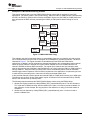
3. Configure the PaRAM set associated with each regular channel by calling
EDMA3_DRV_setSrcParams().
• The field values of the PaRAM set corresponding to the first channel are as follows:
– SRC should be the start address of the PING buffer in the external memory.
– DST should be the start address of the PING buffer in the internal memory.
– SRCBIDX = 4096, DSTBIDX = 4096, ACNT = 4096, BCNT = 1 and CCNT = 1. This indicates
that each transfer is configured as a 1-D transfer copying 4096 bytes (1K elements). The
values of SRCCIDX and DSTCIDX do not matter in this example.
– OPT.SYNCDIM = SYNC_AB, OPT.TCINTEN = ENABLE, and OPT.TCCMODE = NORMAL.
This indicates that after the PING buffer is copied, you will be notified by an interrupt.
• The field values of the PaRAM set corresponding to the second channel are as follows:
– SRC should be the start address of the input PONG buffer in the external memory.
– DST should be the start address of the PONG buffer in the internal memory.
– Values of SRCBIDX, SRCCIDX, ACNT, BCNT, and CCNT are the same as for the first
channel.
– Values of OPT.SYNCDIM, OPT.TCINTEN, and OPT.TCCMODE are the same as for the first
channel.
4. Chain the regular channels to each other by calling the EDMA3_DRV_chainChannel() twice.
5. For each regular channel, link it with the corresponding link channel by calling
EDMA3_DRV_linkChannel(), then copy its PaRAM set content to the linked channel’s PaRAM set.
6. Manually enable the first transfer of the first channel to fill the PING buffer by calling
EDMA3_DRV_enableTransfer(). Once it is completed, an interrupt is generated and the next transfer
of the second channel to fill the PONG buffer is triggered automatically. When the PONG buffer is
filled, the data in the PING buffer can be processed.
7. The transfer continues for a specified number of times. After the example is finished, all the channels
need to be freed by calling EDMA3_DRV_freeChannel().
6
Package Usage Guide
6.1
Hardware and Software Requirement
The following equipment and software are needed to compile and execute the provided example code.
• A PC with Microsoft® Windows XP® operating system pre-installed
• Texas Instruments Code Composer Studio™ 3.3 (CCStudio) software already installed on PC
• A TMS320DM6437 evaluation module (EVM) board
6.2
Package Contents
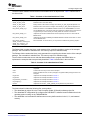
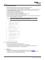
The package provided is compressed as a file called spraan4.zip. Unzipping the package to the PC
creates a folder called edma3test. There are six sub-folders in the edma3test folder: CSL_inc, driver,
Debug, Release, test, and edma3test.CS_.
The CSL_inc folder contains the chip support library (CSL) header files of all the peripherals on
TMS320DM643x. These files implement the polling mode that checks that the transfer is complete, which
works around the limitation of the current EDMA3 driver. These header files will not be needed if you use
a future driver without the limitation.
12
How to Use the EDMA3 Driver on a TMS320DM643x Device
SPRAAN4A – June 2008
Submit Documentation Feedback