1
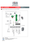
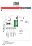
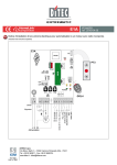
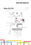
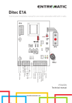
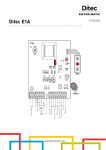
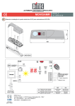
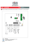
E1HBOX IP1982EN rev. 2012-03-22 EN Installation manual for control panel for BOX3EH automation. ENC Motor 1 -M +M Black Blue 24V ANT JR4 Motor 2 BIXMR2 Blue Black 6►4 AUX 24V IN COM SO PRG GOL4 BAT SIG BATK4 11 SA 24 V~ JR3 ON OFF 1 2 3 4 5 12 C NO 14 0 12 11 0 VA VC TC R1 Step-by-step 1 5 9 13 0 1 6 8 + Safety stop Safety re-opening POWER ALARM Step-by-step Stop Door open indicator light Transformer DITEC S.p.A. Via Mons. Banfi, 3 - 21042 Caronno Pertusella (VA) - ITALY Tel. +39 02 963911 - Fax +39 02 9650314 www.ditec.it - [email protected] Output 24 V max 0.3 A Opening limit switch Closing proximity switch Power supply Flashing light F1 INDEX Subject 1. 2. 3. Page General safety precautions EC declaration of conformity Technical data 3 4 4 4 4 5 6 7 9 10 11 3.1 Applications 4. 5. 6. 7. 8. 9. 10. Connection of power supply Commands Outputs and accessories Adjustments Radio receiver operation Start-up Troubleshooting CAPTION This symbol indicates instructions or notes regarding safety issues which require particular attention. i This symbol indicates informations which are useful for correct product function. This symbol indicates instructions or notes intended for technical and expert personnel. STOP This symbol indicates operations not to be effected for not compromise the correct operation of the automation. This symbol indicates options and parameters which are only available with the indicated item. This symbol indicates options and parameters which are not available with the indicated item. All right reserved All data and speci¿cations have been drawn up and checNed with the greatest care. The manufacturer cannot however taNe any responsibility for eventual errors, ommisions or incomplete data due to technical or illustrative purposes. IP1982EN 2012-03-22 2 1. GENERAL SAFETY PRECAUTIONS This installation manual is intended for quali¿ed personnel only. The installation, the power connections and the settings must be completed in conformity with Good :orNing Methods and with the regulations in force. Before installing the product, carefully read the instructions. Bad installation could be ha]ardous. The pacNaging materials (plastic, polystyrene, etc.) should not be discarded in the environment or left within reach of children, as these are a potential source of hazard. Before beginning the installation checN that the product is in perfect condition. 'o not install the product in explosive areas and atmospheres the presence of Àammable gas or fumes represents a serious threat to safety. The safety devices (photocells, sensitive edges, emergency stop, etc.) must be installed taNing into account the provisions and the directives in force, Good :orNing Methods, the installation area, the functional logic of the system and the forces developed by the automation. Before maNing power connections, checN that the rating corresponds to that of the mains supply. A multipolar disconnection switch with a contact opening gap of at least 3 mm must be included in the mains supply. ChecN that upstream of the electrical installation an adequate residual current circuit breaNer and an overcurrent cut out are ¿tted. When requested, connect the automation to an effective earthing system carried out as indicated by current safety regulations. During installation, maintenance and repair operations, cut off the power supply before opening the cover to access the electrical parts. To handle electronic parts, wear earthed antistatic conductive bracelets. The manufacturer of the motorisation declines all responsibility in the event of components which are not compatible with the safe and correct operation of the product. For repairs or replacements of products only original spare parts must be used. 3 IP1982EN 2012-03-22 2. EC DECLARATION OF CONFORMITY Manufacturer: DITEC S.p.A. Address: via Mons. Ban¿, 3 21042 Caronno P.lla (VA) - ITALY declares that the control panel E1HBOX (with receiver 433.92 MHz) is in conformity with the provisions of the following EC directives: R&TTE Directive 1999/5/EC; EMC Directive 2004/108/EC; Low Voltage Directive 2006/95/EC. Caronno Pertusella, 01-09-2010 3. Silvano Siilvano Angaroni S An A ngaroni ((Managing Ma M an na ag giing gD Director) iirre ecctto or) r) TECHNICAL DATA E1HBOX Power supply F1 fuse 1 motor output 2 motors output Accessories power supply Temperature Degree of protection Memorizable radio codes Radio frequency i 230 V~ 50/60 Hz F1.6A 24 V 9 A max 24 V 2x5.5 A max 24 V 0.3 A min -20 °C max +55 °C IP24D 200 433.92 MHz NOTE: the given operating and performance features can only be guaranteed with the use of DITEC accessories and safety devices. 3.1 Applications 4. CONNECTION OF POWER SUPPLY Before connecting the power supply, maNe sure the plate data correspond to that of the mains power supply. An omnipolar disconnection switch with minimum contact gaps of 3 mm must be included in the mains supply. ChecN that upstream of the electrical installation there is an adequate residual current circuit breaNer and a suitable overcurrent cutout. Use a H05RN-F 3G1,5 or H05RR-F 3G1,5 type electric cable and connect to the terminals L (brown), N (blue), (yellow/green) in the automation. Secure the cable using a special cable clamp. MaNe sure there are no sharp edges that may damage the power supply cable. Connection to the mains power supply, in the section outside the automation, is made with independent channels and separated from the connections to the control and safety devices. IP1982EN 2012-03-22 4 5. 1 COMMANDS Command Function 5 N.O. STEP-BY-STEP WITH AUTOMATIC CLOSING 1 6 N.C. 1 6 N.O. 1 8 N.C. 1 1 9 9 N.C. N.O. 0 11 N.C. 0 12 N.C. N.O. PRG Description With DIP1=OFF and TC<MAX, the closing of the contact activates opening or closing operations in the following sequence: open-stop-close-open. NOTE: the stop is not permanent but lasts for a duration set by TC. STEP-BY-STEP With DIP1=OFF and TC=MAX, the closing of the contact actiWITHOUT AUTOMATIC vates opening or closing operations in the following sequence: CLOSING open-stop-close-open. OPENING WITH With DIP1=ON and TC<MAX, the closing of the contact actiAUTOMATIC vates the opening operation. CLOSING OPENING WITHOUT With DIP1=ON and TC=MAX, the closing of the contact actiAUTOMATIC vates the opening operation. CLOSING NOTE: once the automation stops, the closing of the contact performs the opposite operation to the one performed before stop. SAFETY STOP With 6Ź4=ON, all operations are stopped and/or blocNed when the safety contact is opened. CLOSING With 6Ź4=OFF, the closing of the contact activates the closing operation. REVERSE The opening of the safety contact triggers a reversal of motion SAFETY CONTACT (re-opening) during closing. STOP The opening of the safety contact stops the current operation. HOLD-TO-RUN The opening of the 1-9 contact enables the hold-to-run funcFUNCTION tion. - hold-to-run opening 1-5 [with DIP1=ON]; - hold-to-run closing 1-6 [with 6Ź4=OFF]. NOTE: any safety device, automatic closing and plug-in card inserted in AUX is disabled. CLOSING PROXIMITY With DIP2=OFF, after the contact has opened, the closing LIMIT SWITCH movement stops on the mechanical stop. With DIP2=ON, the opening of the contact stops the opening operation. OPENING With DIP2=OFF, the opening of the contact stops the opening LIMIT SWITCH operation. With DIP2=ON, after the contact has opened, the closing movement stops on the mechanical stop. TRANSMITTERS WARNING: the BIXMR2 storage module must be inserted. STORAGE AND Transmitter storage: CANCELLATION - press the PRG Ney (the SIG LED comes on), - transmit the transmitter to be stored (the SIG LED Àashes), - wait 10 s to complete storage (the SIG LED goes out). Transmitter cancellation: - press the PRG Ney for 3 sec (the SIG LED Àashes), - press the PRG Ney for another 3 sec (the SIG LED Àashes quicNly). WARNING: make a jumper for all the N.C. contacts if not in use. The terminals with the same number are equal. 5 IP1982EN 2012-03-22 6. OUTPUTS AND ACCESSORIES Output Value - Accessories 0 1 24 V 0.3 A Description Accessories power supply. Power supply output for external accessories, including automation status lamp. - + 1 13 24 V 3 W 0 14 LAMPH 24 V 25 W C NO LUXKBOX 230 V~ 25 W L N 230 V~ 100 W AUX COM BIXMR2 -M +M BAT IP1982EN 2012-03-22 BATK4 2x12 V 1.2 Ah Automation status lamp (proportional). The light switches off when the automation is closed; the light switches on when the automation is open; the light Àashes with a variable frequency while the automation is operating. Flashing light. Activated during opening and closing operations. NOTE: two /AM3+ Àashing lights with 24 9 15 W bulbs can be connected. Internal courtesy light. A courtesy light that turns on for 180 s with every opening (total or partial), step-by-step and closing command can be connected in series to the NO contact. External courtesy light. An external courtesy light that turns on for 180 s with every opening (total or partial), step-by-step and closing command can be connected. The control panel has one housing for plug-in cards such as a radio receiver type, magnetic loops, etc. Plug-in card operating is selected using DIP1. WARNING: the plug-in cards must be inserted and removed with the power supply disconnected. The storage module allows remote controls to be stored. If the control panel is replaced, the BIXMR2 storage module being used can be inserted in the new control panel. WARNING: the storage module must be inserted and removed with the power supply disconnected. Motor-encoder connection. Connect the motor and encoder to the control panel by means of the supplied cables. Battery operating. The batteries are Nept charged when the power supply is on. If the power supply is off, the control panel is powered by the batteries until power is re-established or until the battery voltage drops below the safety threshold. If this occurs, the control panel turns off. WARNING: the batteries must always be connected to the control panel for charging. 3eriodically check the ef¿ciency of the batteries. NOTE: the operating temperature of the rechargeable batteries is approximately +5°C/+40°C. 6 7. ADJUSTMENTS DIP1 DIP2 DIP3 DIP4 Description Command 1-5 operation. NOTE: it also sets operating mode of the plugin cards connected on AUX. Motor installation position. The installation position is intended by viewing the automation from the side being examined. Restore automatic closing time. Automation status at power on. Indicates how the control panel considers automation when powered up. DIP5 3 seconds preÀashing. JR3 JR4 SO Description Automation type. Incorporated radio receiver. Reversal safety switch function. 6Ź4 Command 1-6 operation. OFF Step-by-step. Opening. Central or right side. Left side. 50% Open. NOTE: with limit switches installed, preferably set DIP4=OFF. Disabled during opening. Enabled only with automatic closing with TC>3 s. 100% Closed. NOTE: if the automatic closing function is not used, preferably set DIP4=ON. Enabled for both opening and closing. OFF 2 motors automation. Disabled. With the automation blocNed, if the contact 1-8 is open, it is possible to activate the opening operation. Closing. ON 1 motor automation. Enabled. With the automation blocNed, if the contact 1-8 is open, any operation is impossible. 7 ON Stop. IP1982EN 2012-03-22 Trimmer VA-VC min Description Opening speed adjustment. Adjusts the opening speed. Closing speed adjustment. Adjusts the closing speed. max 12 0 s TC 0s Disabled R1 min LED max Setting automatic closing time. From 0 to 120 s. With DIP3=OFF, once a safety switch has been activated, the counter starts as soon as the safety switch is released (for example after passing through the photocells), and lasts for a period of time set with trimmer TC (50%). With DIP3=ON, the counter starts when automation is opened and lasts for the entire duration set with trimmer TC (100%). NOTE: after the activation of the stop command, once contact 1-9 has closed again, automatic closing is only enabled after a total, partial or step-by-step opening command. Obstacle thrust adjustment. The control panel is equipped with a safety system that stops motion if an obstacle is encountered during an opening operation and inverts the movement during a closing operation. R1=MIN gives maximum obstacle sensitivity (minimum thrust). R1=MAX gives maximum thrust. SIG On Receipt of command or change in status of a dip-switch. Transmitter enabling/storage phase. 11 0-11 limit switch contact is open. SA At least one of the safety contacts is open. 12 0-12 limit switch contact is open. IN / Reception of a radio transmission of a stored transmitter. Reception of a radio transmission of a not stored transmitter. Cancellation of transmitters in progress. Memory damaged. / Safety test failure (terminal 41). Operations count performed (only when control panel is switched on): = 1000 operations = 10000 operations / POWER ALARM Power supply on. IP1982EN 2012-03-22 Flashing Encoder not worNing. 8 8. RADIO RECEIVER OPERATION ANT JR1 SIG COM CH1 CH2 CH3 CH4 PRG 1 2 10 s 3 The control panel is equipped with a radio receiver with a frequency of 433.92 MHz. The antenna consists of a rigid wire, 173 mm long, connected to the ANT clamp. It is possible to increase the range of the radio by connecting the antenna of the Àashing lights, or by installing the tuned BIXAL antenna. NOTE: to connect the external antenna to the control panel, use a coaxial cable type RG58 (max 10 m). ChecN that the storage module is inserted on COM connector of the control panel. Up to 200 remote controls can be stored in the storage module. WARNING: if the radio receiver on the control panel is not used, set JR4=OFF and remove the storage module. Transmitter storage: press the PRG button on the radio receiver or on the control panel; the SIG LED lights up; maNe a transmission by pressing one of the desired CH buttons of the transmitter (within the range of the radio receiver). The transmitter is now stored. During this phase, the SIG LED Àashes. When the SIG LED is again lit up, it is possible to validate another transmitter. Validate all the new transmitters by maNing a transmission as indicated; you automatically exit the procedure 10 s after the last transmission, or you can press the PRG button again (the SIG LED goes off). Up to four CH Neys of a single remote control can be stored: if only one (any) CH Ney of the remote control is stored, command 1-5 (step-by-step/opening) is carried out; from two to four CH Neys of a single remote control are stored, the functions matched with the CH Neys are as follows: CH1 = command 1-5 step-by-step/opening; CH2 = partial opening command; CH3 = command to switch on/off the courtesy light; CH4 = stop command, equivalent to impulsive command 1-9. Transmitter cancellation: Neep pressed for 3 s the PRG button on the radio receiver or on the control panel, the SIG LED begins to Àash; to erase all the transmitters from the memory of the radio receiver Neep pressed for 3 s again the PRG button; to erase a single transmitter, press one of the previously stored CH Neys of the transmitter to be erased; the cancellation is con¿rmed by the quicN Àashing of the SIG LED. For further information see the user manual for GOL series transmitters. If the control panel is replaced, the storage module being used can be inserted in the new control panel. WARNING: the storage module must be inserted and removed with the power supply disconnected. 9 IP1982EN 2012-03-22 9. START-UP WARNING 1234- 5678- 9- i The operations in point 4 are performed without safety devices. The trimmer can only be adjusted with the automation idle. MaNe a jumper for the N.C. safety contacts. If installed, adjust the opening and closing stop limit switches. NOTE: limit switches must be kept pressed until the operation has been completed. Set TC=MAX. Use DIP2 to set the installation position. Switch on and checN that the automation is operating correctly with subsequent opening and closing commands. If installed, checN that the limit switches are activated. Connect the safety devices (removing the relative jumpers) and checN they worN correctly. If required, adjust the automatic closing time with the TC trimmer. WARNING: the automatic closing time after a safety device has triggered depends on the DIP3 setting. Set the desired opening and closing speed using the VA and VC trimmers. Set the obstacle thrust with the R1 trimmer. WARNING: after adjusting check that the working forces exerted by the door wings are compliant with EN12453-EN12445 regulations. Connect any other accessories and checN they operate correctly. NOTE: in the event of servicing or if the control panel is to be replaced, repeat the start-up procedure. IP1982EN 2012-03-22 10 10. TROUBLESHOOTING Problem Possible causes The automation does not No power. open or close. (POWER ALARM led off). Short circuited accessories. (POWER ALARM led off). Blown line fuse. (POWER ALARM led off). Safety contacts are open. (SA led on). The remote control does not worN. External safety devices not activating. The automation opens/ closes brieÀy and then stops. The remote control has limited range and does not worN with the automation moving. Remedy ChecN that the control panel is powered correctly. Disconnect all accessories from terminals 0-1 (voltage must be 24 V ) and reconnect one at a time. Replace F1 fuse. ChecN that the safety contacts are closed correctly (N.C.). ChecN the correct memorization of the transmitters on the incorporated radio. If there is a fault with the radio receiver that is incorporated in the control panel, the radio control code can be read by removing the storage module. Photocells are activated. ChecN that the photocells are clean (SA led on). and operating correctly. The automatic closing does not worN. ChecN that the TC trimmer is not set at the maximum. Incorrect connections between the Connect N.C. safety devices together in photocells and the control panel. series and remove any bridges on the control panel terminal board. Encoder disconnected, false encoder ChecN that the encoder is connected contacts, encoder fault. correctly, clean the contacts by con(POWER ALARM led Àashing). necting and disconnecting the encoder plug on the contacts, replace encoder. Motor leads crossed. ChecN the motor leads. (POWER ALARM led Àashing). There is friction. Manually checN that the automation moves freely, checN the R1 adjustment. The radio transmission is impeded by Install the antenna outside. metal structures and reinforced conSubstitute the transmitter batteries. crete walls. 11 IP1982EN 2012-03-22 TM DITEC S.p.A. Via Mons. Ban¿, 3 21042 Caronno P.lla (VA) Italy Tel. +39 02 963911 Fax +39 02 9650314 www.ditec.it [email protected] DITEC BELGIUM LOKEREN Tel. +32 9 3560051 Fax +32 9 3560052 www.ditecbelgium.be DITEC DEUTSCHLAND OBERURSEL Tel. +49 6171 914150 Fax +49 6171 9141555 www.ditec-germany.de DITEC ESPAÑA ARENYS DE MAR Tel. +34 937958399 Fax +34 937959026 www.ditecespana.com DITEC FRANCE MASSY Tel. +33 1 64532860 Fax +33 1 64532861 www.ditecfrance.com DITEC GOLD PORTA ERMESINDE-PORTUGAL Tel. +351 22 9773520 Fax +351 22 9773528/38 www.goldporta.com DITEC SWITZERLAND BALERNA Tel. +41 848 558855 Fax +41 91 6466127 www.ditecswiss.ch DITEC ENTREMATIC NORDIC LANDSKRONA-SWEDEN Tel. +46 418 514 50 Fax +46 418 511 63 www.ditecentrematicnordic.com DITEC TURCHIA ISTANBUL Tel. +90 21 28757850 Fax +90 21 28757798 www.ditec.com.tr DITEC AMERICA ORLANDO-FLORIDA-USA Tel. +1 407 8880699 Fax +1 407 8882237 www.ditecamerica.com DITEC CHINA SHANGHAI Tel. +86 21 62363861/2 Fax +86 21 62363863 www.ditec.cn