1
SLIMCON-6 USERS GUIDE
SLIMCON-6
24V DC POWERED
ISOLATING SIGNAL CONVERTER
Whilst every effort has been taken to ensure the accuracy of this document, we
accept no responsibility for damage, injury, loss or expense resulting from errors or
omissions, and reserve the right of amendment without notice.
This document may not be reproduced in any way without the prior written
permission of the company.
March 2007
IIG-070501
Page 1
SLIMCON-6 USERS GUIDE
CONTENTS
1.
INTRODUCTION _______________________________________________________3
1.1
Hardware Features _________________________________________________________ 3
1.2
Isolation Details ____________________________________________________________ 3
2.
UNPACKING___________________________________________________________3
3.
QUICK START GUIDE __________________________________________________4
4.
CONNECTIONS ________________________________________________________5
5.
CONFIGURING THE SLIMCON __________________________________________6
5.1
Input and Output Selection___________________________________________________ 7
6.
CALIBRATING THE SLIMCON___________________________________________8
7.
INSTALLATION ________________________________________________________9
7.1
8.
Troubleshooting ____________________________________________________________ 9
SPECIFICATIONS (@ 25°C)_____________________________________________10
IMO Precision Controls Ltd
Page 2
IIG-070501
SLIMCON-6 USERS GUIDE
1.
INTRODUCTION
1.1 Hardware Features
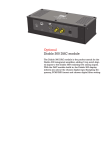
The SLIMCON-6 family of Isolating Signal Converters can accept a range of inputs
including 4-20mA and voltage signals. The unit produces high level DC output of
either voltage or current.
The input and output of the unit can be reconfigured using the built in switches
together with the zero and span adjustment potentiometers.
The unit can be powered by any DC voltage between 18 and 30Vdc (22V at least
required to drive into 500 ohms).
The instrument is packaged in an ultra slim 7.5mm wide enclosure which can be
mounted on standard TS35 DIN-rail.
1.2 Isolation Details
The SLIMCON has full 3 port isolation of 1000V between the Input Stage, Output
Stage and Power Supply for functional reasons.
2.
UNPACKING
The instrument should be carefully inspected for signs of damage which may have
occurred in transit. In the unlikely case that damage has been sustained, DO NOT
use the instrument, but please retain all packaging for our inspection and contact
your supplier immediately.
The instrument comes with the following items as standard:
1
SLIMCON-6 Isolating Signal Converter
1
SLIMCON-6 User Guide
If the instrument has been factory configured the input and output details will be
listed on the Serial number label on the side of the unit.
If re-configuration is required please refer to section 5 of this manual.
IIG-070501
Page 3
SLIMCON-6 USERS GUIDE
3.
QUICK START GUIDE
This example shows how easy it is to configure a SLIMCON-6 with
4-20mA Input, 0-10V Output
!
! WARNING !
DO NOT ADJUST SWITCHES WITH POWER SUPPLY,
INPUT OR OUTPUT CONNECTED
Set up the switches to the required type and range (see page 7) using the blade edge
of a small flat screwdriver (or similar small pointy implement).
E.G.
For 4-20mA Input, 0-10V Output,
S1: 1,2,3 are on
S2: 2,3,4,6 are on
Connect up the inputs, output and power supply and switch on (page 5)
Apply full scale input value (20mA)
Adjust span pot to required output value 10V
Apply zero scale input (4mA)
Adjust zero pot to required output value 0V
Repeat the 4 previous steps until the output is correctly calibrated.
Page 4
IIG-070501
SLIMCON-6 USERS GUIDE
4.
CONNECTIONS
The SLIMCON-6 is housed in a compact DIN rail mounting enclosure, with 8
terminals, 4 on top and 4 underneath.
The diagram below shows how to connect the different input, output and power
supply types.
NC
8
8
10
Current Sink -ve
10 - ve
OUTPUT
12
0-10V
12 +ve
Voltage Source
Span Adjust
Zero Adjust
5
4
5 +ve Input: mA, Volts
INPUT
2
1
IIG-070501
4-20mA Sink
POWER
4 - ve
2 18-30Vdc
1 0V
Page 5
0(4)-20mA
Current Source
Current Sink
+ 24V Supply
SLIMCON-6 USERS GUIDE
5.
CONFIGURING THE SLIMCON
!
! WARNING !
DO NOT OPEN UNIT OR ADJUST SWITCHES WITH
POWER SUPPLY, INPUT OR OUTPUT CONNECTED
The SLIMCON can support Voltage and mA inputs. The unit is configured by
turning the power off, selecting the switch settings required on the side of the unit
and turning the power back on.
The switches are accessed through two cut-outs in the side of the enclosure.
There are 2 switch banks, S1 and S2:
ON
4
Switch S2 1
Switch S1 1
5
6
OFF
Switch 4 is OFF
Switch 5 is ON
Switch 6 is OFF
6
4
Switch S1 configures the input type and range and switch S2 configures the output
type and range. The switch settings are explained on the next page.
Page 6
IIG-070501
SLIMCON-6 USERS GUIDE
5.1
Input and Output Selection
Select the input and output ranges from the table below and set Switches S1 and S2
to the required values.
S1 SWITCH
1 2 3 4
IN
OUT
4-20mA
4-20mA
4-20mA
4-20mA
4-20mA
0-20mA
0-10V
0-5V
1
1
1
1
1
1
1
1
1
1
1
1
0-20mA
0-20mA
0-20mA
0-20mA
4-20mA
0-20mA
0-10V
0-5V
1
1
1
1
1
1
1
1
1
1
1
1
0-10V
0-10V
0-10V
0-10V
4-20mA
0-20mA
0-10V
0-5V
0-5V
0-5V
0-5V
0-5V
4-20mA
0-20mA
0-10V
0-5V
0-10mA
0-10mA
0-10mA
0-10mA
4-20mA
0-20mA
0-10V
0-5V
1
S2 SWITCH
2 3 4 5
1
1
1
1
1
1
1
1
1
1
6
1
1
1
1
1
1
1
1
1
1
1
1
1
1
1
1
1
1
1
1
1
1
1
1
1
1
1
1
1
1
1
1
1
1
1
1
1
1
1
1
1
1
1
1 = SWITCH ON
!
IIG-070501
! WARNING !
DO NOT ADJUST SWITCHES WITH POWER SUPPLY,
INPUT OR OUTPUT CONNECTED
Page 7
SLIMCON-6 USERS GUIDE
6.
CALIBRATING THE SLIMCON
When the unit is shipped the SLIMCON will be calibrated for the input and output
types and ranges noted on the side label. If this label is blank then the unit will be
calibrated for 4-20mA input and 4-20mA source output.
The span and zero points are adjusted using the potentiometers accessible on the
front panel.
Apply full scale input value
Adjust span pot to required output value
Apply zero scale input
Adjust zero pot to required output value
Repeat the four previous steps until the output is correctly calibrated.
Page 8
IIG-070501
SLIMCON-6 USERS GUIDE
7.
INSTALLATION
The SLIMCON’s input and output circuits are classed as Separated Extra Low
Voltage (SELV). This means that they must not be externally connected to voltages
exceeding 30V ac or 60V dc, nor do they generate voltages above these limits
internally. Where a higher voltage input is required a specially designed DIVIDER
unit can be used to condition the input signal prior to connection to the process
input terminals.
The SLIMCON unit clips directly onto ‘Top Hat’ (TS35) symmetrical DIN rail.
Ideally, mounting orientation should be vertical. Good airflow around the unit will
maximise reliability of the instrument.
The use of bootlace ferrules is recommended on wiring terminations.
Do not exceed terminal torque rating of 0.4 Nm – use an appropriate screwdriver.
The unit can be removed from the DIN rail by sliding a small screwdriver into the
slot at the rear of the enclosure on the lower face and gently levering the metal clip,
whilst lifting the unit from the rail.
7.1
Troubleshooting
•
•
•
•
Check that the switch settings are correct.
Check that sensor wiring is correct.
Check that applied voltage is not out of range.
Check that applied current is not out of range.
IIG-070501
Page 9
SLIMCON-6 USERS GUIDE
8.
SPECIFICATIONS (@ 25°C)
Operating Temperature
Power Requirements DC Supply
Current Consumption
Volt Drop (mA input)
Calibration accuracy
Output Linearity
Temperature Stability
Load Resistance Error
Time Constant (10-90%)
Input Impedance:
Current Input Typical
Current Input Max
Voltage Input
0 to 55 °C
18 to 30Vdc (22Vdc required to drive 500Ω)
25mA @ 24Vdc into 500Ω
0.1V (max 0.15V at 20mA input)
±0.05% full scale
±0.03% full scale (max 0.1%)
±100ppm / °C
±5ppm/ohm (load between 0 and 500Ω)
25mS (max 30mS)
Operating Altitude
Humidity
Sea Level to 2000m
0-90% RH
5 Ω (typical 20mA range)
10 Ω (max on 0-10mA range)
500k
Unit has full 3 port Isolation to 1kV between Power Supply, Input and Output.
The unit can also withstand transients of 2.5kV for 50 µsecs.
Dimensions
Mounting
Connections
Conductor Size
Insulation Stripping
Maximum Terminal Torque
Weight
EMC
LVD Standards
Installation Category (IEC 664)
Pollution Degree (EN61010-1)
Equipment Class (IEC 536)
93.1mm x 102.5mm x 6.2mm (H x D x W)
DIN Rail TS35
Screw Clamp with pressure plate
0.5 to 4.0 mm
12 mm
0.4 Nm
Approx. 140g
BS EN61326
EN61010-1
II
2
II
Page 10
IIG-070501