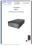
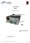
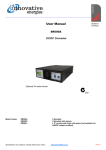
1
User Manual
SE, SL
No-BreakTM DC UPS - Security series
35 - 150W
Specifications are subject to change without notice.
02-May-12
Safety
The user is responsible for ensuring that input and output wiring segregation complies with local standards and that in
the use of the equipment, access is confined to operators and service personnel. A low resistance earth connection is
essential to ensure safety and additionally, satisfactory EMI suppression (see below).
HAZARDOUS VOLTAGES EXIST WITHIN A POWER SUPPLY ENCLOSURE AND ANY REPAIRS MUST
BE CARRIED OUT BY A QUALIFIED SERVICEPERSON.
Electrical Strength Tests
Components within the power supply responsible for providing the safety barrier between input and output are constructed to provide electrical isolation as required by the relevant standard. However EMI filtering components could be
damaged as result of excessively long high voltage tests between input, output and ground. Please contact our technicians for advice regarding electric strength tests.
Earth Leakage
The EMI suppression circuits causes earth leakage currents which may be to the maximum allowable of 3.5mA.
Ventilation
High operating temperature is a major cause of power supply failures, for example it has been well documented that a
10oC rise in the operating temperature of a component will halve its expected life. Therefore always ensure that there is
adequate ventilation for the equipment. Batteries and cooling fans also suffer shortened lifetimes if subjected to high
ambient temperatures - both should be included in a routine maintenance schedule to check for signs of reduced efficiency.
Water / Dust
Every effort must be made in the installation to minimise the risk of ingress of water or dust. Water will almost always
cause instant failure. The effects of dust are slower in causing failure of electronic equipment but all electrical equipment should be cleaned free of any dust accumulation at regular intervals. This is particularly important where internal
fans are fitted.
Electromagnetic Interference (EMI)
Switching power supplies and converters inherently generate electrical noise. All wiring should be as short as practicable and segregated from all equipment wiring which is sensitive to EMI. Residual noise can be reduced by looping DC
wiring through ferrite cable sleeves. These are most effective as close to the power supply as possible and as many
turns of the wire taken through the core (+ and - in the same direction) as the core will accommodate.
Fuse ratings
Check that the wiring and fuses or MCBs match the rating of the PSU or converter. Adequate fuse protection of battery
circuits is very important owing to the large potential currents available from batteries.
Connection polarity
It is critical to check the polarity carefully when connecting DC power supplies and chargers to equipment. Boost
chargers and some float chargers usuall have reverse polarity protection (RPP), which can be electronic (nondestructive) or by an internal fuse which needs to be replaced if a battery is connected in reverse.
Glossary of terms used in our user manuals
PSU = power supply unit
BCT = battery condition test
ELVD = electronic low voltage disconnect RPP = reverse polarity protection
SNMP = Simple Network Management
Protocol
Specifications are subject to change without notice.
LAN = local area network
2
ECB = electronic circuit breaker
EMI = electromagnetic interference
Check polarity before connecting batteries.
These power supplies/ chargers are designed to be used with batteries for correct operation.
Specifications are subject to change without notice.
3
75 & 150W DC back up for security systems
Uninterruptible No-Break DC Power Supply /
battery back-up system
Universal AC input: 85 - 264V
Reverse polarity protection
• Alarms included as standard
Electronic Low Voltage Disconnect
Independent battery charge current limit
Room for up to 4 x 7 Ah batteries
4 x separately fused load outputs
1 x fused battery output
Designed for use with lead acid batteries
•
‘Knockout’ holes for top or bottom cable entry
♦ 24 Month Warranty
SPECIFICATIONS All specifications are typical at nominal input, full load and at 20°C unless otherwise stated.
No-Break™ FUNCTIONS AND ALARMS
ELECTRICAL
Reverse Polarity
Battery reverse connection will open internal
fuse (and produce alarm)
Internal AC input fuse, DC output fuses
Electronic Low Volts
Disconnect (ELVD)
Disconnects battery when discharged,
(10V for 12V systems, 20V for 24V systems)
Isolation
1KV DC input / output to earth
Load Dump Jumper
Loads may be disconnected using external
relay contact (jumper fitted ex factory)
Efficiency
> 87%
Output Power
75W & 150W
Alarms
•
Output Voltages
13.8V , 27.6V
•
Voltage adj. range
85 - 105% of Vout
•
Charge Current Limit
Refer to model table
Line Regulation
+/-1%
Load Regulation
+/-2%
Over Volts Protection
(OVP)
Yes, reset by power off
Input
90 - 264VAC (47-63Hz) / 2.88 - 1.2A
Power Factor
>0.92
Fusing / Protection
Tamper switch activates when enclosure
door opened
Power Fail¹ (alarms when float voltage
drops to approx. 12.8V/25.6V)
Battery Low¹ (Battery volts = 11V/22V or
reverse polarity)
Alarm Relay Contacts:
C - NO - NC full changeover rated 1A /50V
DC, 32VAC
LED Indicators
•
•
•
AC on
DC outputs OK
Battery fuse OK
PHYSICAL
AC Input connector
Screw / clamp terminal block, (max 2.5mm²)
DC Connections
Screw / Clamp ‘barrier’ terminal
Enclosure
White powder coated steel enclosure with
locking door (lock & 2 keys included)
Battery Compartment
Takes up to four 7Ah batteries
Cooling
Convection
Weight
3.7 Kg
ENVIRONMENTAL
STANDARDS
EMI
To EN55022:2006 Class B
Safety
To IEC950 / EN60950 / UL60950-1 / CSA
Specifications are subject to change without notice.
4
Operating
temperature
0 - 50 degC
Storage temperature
-10 to 85 °C ambient
Humidity
0 - 95% relative humidity non-condensing
75 & 150W
Switch mode DC UPS in security enclosure
STANDARD MODEL TABLE (Suffix -S includes enclosure)
MODELS
Output Voltage
(Load/Battery)
Max. Recomm.
Load Current(A) *1
PSU Rated Current
(A)
Charge
Current Limit (A)
Power
(W)
SE12/05S
13.8V
4.8
5.4
0.6 *2
75
SE12/10S
13.8V
9.5
10.8
1.3
150
SE24/05S
27.6V
4.1
5.4
1.3
150
NOTES:
*1 to allow for adequate charging current for battery after mains failure
*2 may be set to 1.3A if specified at time of order
OPTIONS
Module only:
Use suffix – C instead of -S
Enclosure only:
Order code: SEC-MED
Module only
MOUNTING DETAILS / DIMENSIONS
25mm ROUND CONDUIT ENTRY
218.0
CAUTION
CTRL
LIVE MAINS CONDUCTORS
WITHIN DOTTED AREA
INNOVATIVE ENERGIES LTD
-
IESEC150
REV B
NO-BREAK DC POWER SYSTEM
L
PSU INPUT
LOAD DUMP
RELAY
N
+
MAINS
ON
FU SE OK
LIVE MAINS CONDUCTORS
WITHIN DOTTED AREA
L
-
OUTPUT 1
+
-
OUTPUT 2
+
-
OUTP UT 3
+
-
OUTPUT 4
+
-
N/O
BATTERY
LOW
BATTERY
N/ C
COM
N/O
DC/POWER
FAIL
N /C
COM
INNOVATIVE ENERGIES LTD
IESEC150
-
E
+
COM
CAUTION
CTRL
N
MAINS
INPUT
N/ C
N/O
REV B
TAMPER
NO-BREAK DC POWER SYSTEM
L
ALARMS
300.0
PSU INPUT
117.0
LOAD DUMP
RELAY
N
+
MAINS
ON
FUSE OK
N
253.0
MAINS
INPUT
WIRING ACCESS HOLES 25mm
L
E
+
-
OUTPUT 1
+
-
OUTPUT 2
+
-
+
OUTPUT 3
-
+
OUTPUT 4
-
N/C
COM
BATTERY
LOW
BATTERY
N/O
N/C
COM
DC/POWER
FAIL
N/O
N/C
COM
N/O
TAMPER
ALARMS
119.0
238.0
25mm ROUND CONDUIT ENTRY
Enclosure:
Module:
255.0
306 H x 300 W x 108 D mm
238 L x 117 W mm
295.0
DEPTH 108.0mm
SYSTEM BLOCK DIAGRAM
3A
LOAD DUMP
JUMPER
P
+
N
75 or 150W
SMPS MODULE
∼
∼
∼
∼
F1
1
F2
LED
F3
LED
2
3
LED
F4
SYSTEM
POWER
N/O
COM
N/C
DC
OUTPUTS
4
LED
BATT +
E
-
POWER FAIL
ALARM
CTRL
N/O
COM
N/C
10A
BATTERY
FUSE
∼
BATTERY LOW
ALARM
BATT LED
DISCONNECT
CHARGER
BYPASS
CHARGER
CURRENT
LIMIT
RETURN
Specifications are subject to change without notice.
5
108.5
35 - 138 Watt DC back up for security systems
Uninterruptible No-BreakTM DC Power Supply /
SL12/10S shown
battery back-up system
Designed for security & access control uses
Separately fused battery and load outputs
• Independent battery charge current limit
• Lockable enclosure
Tamper alarm when door is opened
• Reverse battery polarity protection
SL 12/05S & SL12/10S only:
• Mains fail & Battery low (optional on 35W & 40W
models)
Low voltage disconnect to protect batteries
No mains wiring required - can be installed by
non-electrically registered personnel
* Note for NZ customers, these models are available only through Intek
Security Group Ltd (Auckland, Wellington, Christchurch)
SPECIFICATIONS All specifications are typical at nominal input, full load and at 20°C unless otherwise stated.
ELECTRICAL
FUNCTIONS AND ALARMS
AC Input
220-250 VAC, 50Hz , 0.4A
Reverse Polarity
Battery reverse connection will open battery
fuse (and produce alarm)
DC Outputs
2 x Load plus 1 x Battery, all fused with LED
indication
Tamper switch activates when enclosure
door opened
Isolation
1KV DC input - output / earth
13.8V or 27.6V as per model table
Mains Fail1 (also detects PSU fail)
Output Voltages
Alarms
(Mains fail & Battery low
standard for 70W &
138W, optional extra for
35W & 40W)
Current Limits
Refer to model table
¹Contact ratings
NO - NC full changeover rated 1A /50V DC,
32 VAC
Line Regulation
< 0.2% over input range
Indicators
Green LEDs on when fuses OK
Load Regulation
< 0.5% open circuit to full load
Ripple
< 0.2% Pk-Pk, 0.05% RMS
Hold-up time
20ms
Operating Temp.
0°C to 50°C, max. 60°C at 50% load
Battery to Load
Voltage Drop
0.3V max
PHYSICAL
70W & 138W only:
Battery Low Voltage
Disconnect
Set at 10V
Load Dump Jumper
A jumper is fitted on PCB but may be replaced
with a user relay contact to disconnect loads
from battery & PSU
Battery Low (set at 11V )
Enclosure
White powder coated steel enclosure with
locking door (lock & 2 keys included)
Dimensions
35W & 40W: 295 H x 280 W x 76 D
70W & 138W: 335 H x 342 W x 135 D
Weight (with enclosure)
35W & 40W:
70W:
138W:
Mounting
Wall mount via 2 x keyholes at top rear of
enclosure plus 2 holes at bottom
Battery Compartment
Takes up to 4 x 7Ah or 2 x 12Ah batteries
Cable Entry
“Knockout” holes top and bottom, 25mm
diameter and 25mm square/20mm diam.
4kg
6.3 kg
8.2 kg
STANDARDS
EMI
To EN55022 Class A
Safety
EN60950, AS/NZS3260
CONNECTIONS
AC Input Connection
35W & 40W: Hard wired
70W & 138W: IEC 320 connector with 3 Pin
NZ/Aust plug
DC Output
Barrier terminals
Specifications are subject to change without notice.
SL 12/2.5S & SL 24/1.5S
6
35 - 138 Watt
Linear DC UPS in security enclosure
STANDARD MODEL TABLE (Suffix -S includes enclosure, use -C for module only)
Output Voltage
(V)
Max. Recomm.
Load
Current (A)
Charge
Current Limit
(A)
PSU Rated
Current (A)
Power (W)
Mains
Fuse (A)
SL 12/2.5S
13.8
2.0
0.5
2.5
35
1
1
1
SL 24/1.5S
27.6
1.1
0.4
1.5
40
1
1
1
SL 12/05S
13.8
2.6
1.2
3.8
70
3
5
10
SL 12/10S
13.8
6
2.0
8.0
138
3
10
20
MODEL CODES
OPTIONS
Alarms for SL12/2.5 &
SL24/1.5
Load
Battery
Fuses (A) Fuse (A)
NOTE
•
•
Mains Fail
A battery must be connected for loads such as motors and
incandescent lamps which are low resistance on start up.
Battery Low (set at 1.83V / cell)
2 x Relay outputs –clean changeover contacts
rated 1A /50V DC, 32VAC
Module only
Specify suffix -C instead of -S
SYSTEM BLOCK DIAGRAMS
(Two fused load outputs
in parallel)
+ LOAD OUTPUT
INPUT RECTIFIER
+ BATTERY OUTPUT
+
REVERSED
POLARITY
PROTECTION
REGULATOR
LOAD RETURN
LOAD & CHARGING
CURRENT LIMIT
CIRCUITS
BATTERY RETURN
POWER
FAIL
ALARM
ALARMS
(Optional)
BATTERY
LOW
ALARM
SL 12/2.5S
SL 24/1.5S
Load Dump Jumper here
if required
5A or3A10A
OUTPUTS
1
LED
+
Mains
Input
5A or3A10A
POWER
MODULE
2
LED
BATT +
-
POWER
FAIL
ALARM
+
REVERSE
POLARITY
PROTECTION
10A
or 20A
10A
BATTERY
LOW
ALARM
BATT LED
TAMPER
SWITCH
SL 12/05S
SL 12/10S
CHARGER
BYPASS
CHARGE
CURRENT
LIMIT
RETURN
Specifications are subject to change without notice.
7
TERMS OF WARRANTY
Innovative Energies Ltd warrants its power supplies for
24 months (two years) from date of shipment against
material and workmanship defects.
Innovative Energies' liability under this warranty is limited to the replacement or repair of the defective product
as long as the product has not been damaged through
misapplication, negligence, or unauthorized modification
or repair.
Thank you for purchasing from
Innovative Energies.
We trust your power supply will exceed
your expectations and perform for years
to follow.
Sincerely,
The Innovative Energies team.
Innovative Energies Limited
Phone:
Freephone:
+64 9 835 0700
0800 654 668 (New Zealand)
1800 148 494 (Australia)
Fax:
+64 9 837 3446
Email:
[email protected]
Online:
www.innovative.co.nz
In Person:
1 Heremai Street, Henderson, Auckland, New Zealand
By Post:
PO Box 19-501, Auckland 1746, New Zealand
Specifications are subject to change without notice.
8