1
R1L-B/R1L-BR
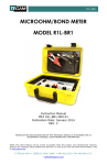
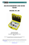
MICROOHMMETER AND
BOND TESTER
MODEL R1L-B, R1L-BR
Instruction Manual
PN# R1L-B/BR-900-01
Publication Date: April 2015
REV. B
REPRODUCTION AND DISTRIBUTION OF THIS TECHNICAL MANUAL IS AUTHORIZED FOR US
GOVERNMENT PURPOSES. TEGAM PROPRIETARY INFORMATION.
NOTE: This User’s Manual was as current as possible when this product was manufactured. However,
products are constantly being updated and improved. To ensure you have the latest documentation, refer
to www.tegam.com
10 TEGAM WAY • GENEVA, OHIO 44041 • 440-466-6100 • FAX 440-466-6110
• [email protected]
TABLE OF CONTENTS
TABLE OF CONTENTS
1. INSTRUMENT DESCRIPTION
Introduction ......................................................... 1-1
Performance Characteristics ................................... 1-1
Description of Equipment ....................................... 1-2
Figure 1a, 1b: Front Panel Controls...................... 1-3
List of Items Furnished .......................................... 1-5
Storage and Shipping Requirements ........................ 1-5
Safety Information and Precautions ......................... 1-5
2. PREPARATION FOR USE AND INSTALLATION
Unpacking and Inspection ...................................... 2-1
Preparation for Use................................................ 2-1
3. OPERATING INSTRUCTIONS
Rotary Switch Functions ......................................... 3-1
General Theory of Operation ................................... 3-2
4. PRINCIPLES OF OPERATION
Principles of Operation ........................................... 4-1
5. MAINTENANCE
Inspection ............................................................ 5-1
Cleaning .............................................................. 5-1
Calibration ........................................................... 5-2
Troubleshooting .................................................... 5-6
Table 2: Fault Symptoms and Repair Actions ........ 5-6
Preparation for Shipment ....................................... 5-7
Overhaul Instructions ............................................ 5-8
Figure 2: Parts Layout ........................................ 5-8
Figure 3, 4: Digital, Analog Section ...................... 5-9
Table 3: Parts List – Main Board Assembly .......... 5-11
Table 4a, 4b: Parts List – Final Assembly ............ 5-14
Table 5a, 5b: Parts List – Front Panel Assembly .. 5-15
Table 6: Parts List – Battery Board Assembly ...... 5-18
Table 7: Vendor Cage Code Directory ................. 5-19
6. SERVICE INFORMATION
Preparation for Repair or Calibration Service ............. 6-1
Expedite Repair and Calibration Form ...................... 6-2
Warranty.............................................................. 6-3
10 TEGAM WAY • GENEVA, OHIO 44041 • 440-466-6100 • FAX 440-466-6110
• [email protected]
TABLE OF CONTENTS
No table of figures entries found.
10 TEGAM WAY • GENEVA, OHIO 44041 • 440-466-6100 • FAX 440-466-6110
• [email protected]
INSTRUMENT DESCRIPTION
SECTION 1
INSTRUMENT DESCRIPTION
1.1 Introduction
The Model R1L-B/R1L-BR is a digital Microohmmeter / Bond
Tester with full scale ranges from 2 mΩ to 20 Ω. The
instrument utilizes the four-terminal, Kelvin technique to
eliminate errors caused by the resistance of the leads. The
resistance reading is displayed on a 3½ digit liquid crystal
display on the front panel. An over-range condition is
indicated as a "1" followed by three blank digits (the decimal
point is also displayed in its normal position for the range
selected).
Model R1L-BR is electronically identical to model R1L-B, but
it has a rugged case as the enclosure rather than an open
front panel.
1.2 Performance Characteristics
This is a range-selection instrument, with a rotary 5 range
selector switch.
Range
1
2
3
4
5
Full
Scale (Ω)
1.999 m
19.99 m
199.9 m
1.999
19.99
Resolution
(Ω)
1µ
10 µ
100 µ
1m
10 m
Test Current
Peak (A)
1.4
140 m
14 m
1.4 m
140 µ
Table 1: Specifications
Accuracy:
Accuracy on all ranges: ± (0.25% of reading + 1 count),
when powered from the batteries only.
10 TEGAM WAY • GENEVA, OHIO 44041 • 440-466-6100 • FAX 440-466-6110
• [email protected]
1-1
INSTRUMENT DESCRIPTION
1.3 Description of Equipment
Physical: The R1L-B circuitry is enclosed in a bench top case,
while the R1L-BR circuitry is enclosed in a rugged portable
case.
Dimensions:
R1L-B: 101 mm (4”) x 292 mm (11.5”) x 203 mm (8”).
Weight is 1.6 kg (3.6 lb).
R1L-BR: 127 mm (5”) x 254 mm (10”) x 228 mm (9”).
Weight is 3 kg (6.7 lb).
Controls and connectors are of a size and spacing such that
the instrument may be operated while wearing safety gloves.
Electrical: The R1L-B/R1L-BR is powered by an internal
battery consisting of three rechargeable NiCad ‘C’ cells (2800
mAh - 3500 mAh) with a built-in charger. Input power for
the charger is 90 to 250 VAC at 50 Hz or 60 Hz. Charging
power is supplied via a removable line cord; one end of which
plugs into a line filter on the front of the R1L-B/R1L-BR, and
the other end being a standard three-pin grounded line plug.
Fuse: ¼ A 3AG Slow blow, TEGAM PN#FU-202
Input Protection: The R1L-B/R1L-BR will not be damaged by
a signal of 1 Vp-p applied across any pair of input terminals.
Environmental: This unit will operate over a temperature
range from 0 °C to 50 °C, 75% RH non-condensing, up to
3050 m altitude.
Front Panel Controls and Displays (See figures 1a and 1b)
RANGE Switch. The rotary 5 range selector switch may be
used to step through all five ranges.
POWER Switch. Used to turn the power on or off to the
instrument.
DISPLAY is a 3 ½ digit, displaying readings from 1.999 to
199.9.
10 TEGAM WAY • GENEVA, OHIO 44041 • 440-466-6100 • FAX 440-466-6110
• [email protected]
1-2
INSTRUMENT DESCRIPTION
Four binding posts for connection of test leads are marked
+I, +E, -E, and -I. Proper connections to the resistor under
test are described in Section 3.2 below.
Figure 1a: R1L-B Front Panel Controls
10 TEGAM WAY • GENEVA, OHIO 44041 • 440-466-6100 • FAX 440-466-6110
• [email protected]
1-3
INSTRUMENT DESCRIPTION
Figure 1b: R1L-BR Front Panel Controls
10 TEGAM WAY • GENEVA, OHIO 44041 • 440-466-6100 • FAX 440-466-6110
• [email protected]
1-4
INSTRUMENT DESCRIPTION
1.4 List of Items Furnished
1 each Model R1L-B/R1L-BR with power cord
3 each rechargeable NiCad battery cells (P/N: BA-110)
2 each Kelvin Clip Cables, one end with a dual banana
plug and the other end with a gold plated Kelvin clip
(P/N: KTL-100) (only included with the R1L-B)
1 each R1L-B/R1L-BR Instruction Manual (P/N: R1LB/BR-900-01)
1.5 Storage and Shipping Requirements
Standard precautions which apply to electronic test
instruments should be followed. Care should be taken to
prevent damage to associated cables.
Remove the battery cells for inactive storage of 30 days
or more.
Temperature: -40 °C to +71 °C.
Relative humidity: 0 to 100%, non-condensing.
Altitude: 4570 m
See Section 5.7 below for shipping requirements.
1.6 Safety Information and Precautions
!
Grounding the Equipment
This product is grounded through the grounding
conductor of the power cord. To avoid electrical shock or
other potential safety hazards, plug the power cord into
a properly wired receptacle before using this instrument.
The proper grounding of this instrument is essential for
safety and optimizing instrument operation.
Danger Arising from Loss of Ground
If the connection to ground is lost or compromised while
charging the batteries, a floating potential could develop
in the instrument. Under these conditions all accessible
10 TEGAM WAY • GENEVA, OHIO 44041 • 440-466-6100 • FAX 440-466-6110
• [email protected]
1-5
INSTRUMENT DESCRIPTION
parts, including insulating parts such as knobs and
terminals could develop a hazardous voltage and put the
user at risk.
Use the Proper Fuse
To avoid fire hazard, use only the correct fuse type as
specified for the AC power supply in the “Description of
Equipment” or “Maintenance” sections of this manual.
Do Not Use in Explosive Environments
The R1L-B/R1L-BR microohmmeter is not designed for
operation in explosive environments.
10 TEGAM WAY • GENEVA, OHIO 44041 • 440-466-6100 • FAX 440-466-6110
• [email protected]
1-6
PREPARATION FOR USE AND INSTALLATION
SECTION 2
PREPARATION FOR USE AND INSTALLATION
2.1 Unpacking and Inspection
Upon receipt, the R1L-B/R1L-BR and accessories should be
carefully unpacked and removed from the shipping
container. Separate the units from the packing material and
inspect both the instrument and the accessories (if any) for
any external damage.
• If any dents, broken, or loose parts are seen, do not use
the equipment. Notify TEGAM immediately.
• Check that all items are present. If any items are missing,
notify TEGAM immediately.
2.2 Preparation for Use
Battery Installation
Note that the instrument is shipped with its battery
removed. Unwrap the 3 cells which comprise the battery.
Be sure the power line cord is disconnected. Check that the
Power Switch is in the OFF position. Remove the four screws
at the corners of the R1L-B/R1L-BR’s top (control/display)
panel. Carefully lift the unit out of its cabinet. Place the unit
upside down on a surface which will not mar or damage the
control/display panel.
WARNING
DO NOT CONNECT THE AC LINE CORD PRIOR TO
REMOVING THE UNIT FROM ITS CASE OR WHILE THE UNIT
IS OUT OF ITS CASE, OR ELSE THE MAINS VOLTAGE WILL
PRESENT A POSSIBLE SHOCK HAZARD.
CAUTION
BE SURE TO OBSERVE THE PROPER POLARITY WHEN
INSERTING THE BATTERY CELLS OR DAMAGE MAY RESULT.
10 TEGAM WAY • GENEVA, OHIO 44041 • 440-466-6100 • FAX 440-466-6110
• [email protected]
2-1
PREPARATION FOR USE AND INSTALLATION
For R1L-B units only, remove the two screws that secure
the battery retention plate.
Insert the battery cells, one at a time, in accordance with
the polarity indications marked on both the battery cell and
the battery holder. Insert the positive end of the battery
cells first.
After installing the cells, reinstall the plate (for R1L-B only),
reinstall the instrument in its case, and secure the four
corner screws.
Power Up
Plug the power cord into the R1L-B/R1L-BR front panel
receptacle, and plug the other end into a standard AC outlet.
For battery operation (with charged battery cells), this step
is omitted. Turn on the POWER rotary switch. Note that this
switch turns on both line and battery power.
Charging the Battery Cells
Prior to battery operation, it is recommended the R1LB/R1L-BR Microohmmeter be plugged into AC power for at
least 14 hours to charge the battery cells. To charge the
battery cells, the Power Switch must be turned ON, and the
Range Switch should be set to 20 Ω. With the Range Switch
set to lower ranges, the charge rate decreases and the
batteries will be discharged, especially on the 2 mΩ range,
even with no resistance connected to the instrument.
(However, the discharge rate in this range will permit
operation for at least 14 hours with no resistance
connected.)
WARNING
ALTHOUGH THE FRONT PANEL IS NORMALLY GROUNDED
VIA THE GROUND PIN OF THE POWER CABLE, IF THIS
CONNECTION IS FAULTY AND IF THE HIGH SIDE OF THE
POWER CABLE IS SHORTED TO THE PANEL, THE PANEL
COULD POSSIBLY HAVE MAINS VOLTAGE ON IT; SO DO
NOT TOUCH THE PANEL WHEN AC POWER IS
CONNECTED.
10 TEGAM WAY • GENEVA, OHIO 44041 • 440-466-6100 • FAX 440-466-6110
• [email protected]
2-2
OPERATING INSTRUCTIONS
SECTION 3
OPERATING INSTRUCTIONS
Use the cables connecting their banana plug terminations to
the four binding posts marked +I, +E, -E, and -I.
WARNING
DO NOT TOUCH THE BINDING POSTS WHEN THEY ARE
CONNECTED
TO
EXTERNAL
CIRCUITS.
LETHAL
VOLTAGES MAY BE PRESENT AT THESE POSTS.
3.1 Rotary Switch Functions
Operation of the Model R1L-B/R1L-BR is extremely simple.
There are only two switches.
The RANGE rotary switch manually scrolls through the five
ranges.
Full scale on any range may be described as 2,000 (actually
1,999), since this is a 3½ digit meter. If the readings are
exceeding 1,999 counts, step to the next higher range. If the
readings are less than 2,000 counts, step down a range, so
that it will read 1,999 counts, or less. The decimal point is
located automatically for the correct reading.
If the selected range is too low for the value of the resistor
under test, the display will show over-range.
The POWER rotary switch turns on the power to operate the
unit or turns off the power to the unit. The appearance of the
display will show that power is on; absence of the display
indicates that either power is off, batteries are discharged, or
there is some malfunction. Note that when power is turned
off, it may take several seconds to discharge circuit capacity
to completely blank the display. The black markings seen
have no effect and disappear when power is turned back on.
10 TEGAM WAY • GENEVA, OHIO 44041 • 440-466-6100 • FAX 440-466-6110
• [email protected]
3-1
OPERATING INSTRUCTIONS
3.2 General Theory Of Operation
Measurement Principle
A 4-terminal measurement method is used to determine the
resistance of the item under test. This method allows the
accurate measurement of low values of resistance in spite of
the other resistances present in the connection leads. A
known current is supplied to the item under test via two wire
leads connected to the +I and -I binding posts on the R1LB/R1L-BR Microohmmeter front panel. Two other wire leads
connected to the +E and -E binding posts on the R1L-B/R1LBR front panel sense the voltage developed across the
resistance under test due to the supplied known current. The
R1L-B/R1L-BR then calculates the resistance of the item under
test utilizing Ohm's law, and displays it on a 3 ½ digit display.
Kelvin Klip Cable Description
A Kelvin clip consists of two opposing jaws of an alligator
style clip which are insulated from each other, so one jaw may
be used to connect a source of current to the resistance
under test, and the other jaw used to measure the voltage at
the test point. The two jaws are spring loaded to clamp onto
a cylinder of ½ inch diameter or less.
WARNING
OPERATING THE R1L-B/R1L-BR MICROOHMMETER AND
TAKING RESISTANCE MEASUREMENTS ON A POWERED OR
ENERGIZED COMPONENT COULD CAUSE SERIOUS HARM
TO THE OPERATOR AND/OR DAMAGE THE INSTRUMENT.
BE SURE THE ITEM TO BE MEASURED IS DISCONNECTED
FROM OTHER COMPONENTS AND APPARATUS.
If the battery cells have not been installed, refer to section
2.2. Battery only operation will result in the most stable and
accurate readings. The R1L-B/R1L-BR may be operated while
charging the batteries, however it will not conform to
specifications in this configuration.
10 TEGAM WAY • GENEVA, OHIO 44041 • 440-466-6100 • FAX 440-466-6110
• [email protected]
3-2
OPERATING INSTRUCTIONS
NOTE: The amount of current available for charging the
battery decreases as lower resistance ranges are selected. In
the 2 mΩ range, the current supplied to the resistance under
test exceeds the charging current, and the battery will be
drained.
To obtain the best accuracy, allow the R1L-B/R1L-BR to
warm up for 15 minutes on the 20 Ω range before making
measurements. Even if in battery operation, this will not
cause appreciable battery discharge.
Using the Kelvin-Clip cables
Plug one Kelvin-Clip cable dual banana plug across the +E
and +I binding posts, and plug the other Kelvin-Clip cable
dual banana plug across the -E and -I binding posts. Note
that in both cases, the small "I" marked on the dual banana
plug should go into the respective I binding post.
If Kelvin-Clip cables are not used, a pair of shielded cables
may be utilized. As occurs in the Kelvin-Clip cables in the
above paragraph, one cable should have its shield connected
to the “+I” binding post and its center conductor connected
to the +E binding post. Similarly, the other cable should
have its shield connected to the -I binding post and its
center conductor to the -E binding post. It is also
recommended that the resistance of the cables should not
exceed 350 mΩ/conductor.
NOTE: Particularly in the 2 mΩ range, where a test current
of approximately 1 . 4 A is used, excessive lead resistance
will prevent an accurate measurement.
Set the Range Switch to the desired measurement range and
read the resistance on the liquid crystal display. If the
resistance is higher than the selected range, the display will
show a "1" and three blank digits, indicating over-range. The
decimal point will also appear in the proper location for the
selected range.
10 TEGAM WAY • GENEVA, OHIO 44041 • 440-466-6100 • FAX 440-466-6110
• [email protected]
3-3
OPERATING INSTRUCTIONS
After prolonged operation on battery power, when the
battery voltage approaches the end of its useful range, the
"LO BAT" indicator will be seen on the display. Although the
battery cells are not fully discharged and they will not be
damaged by additional use, this is a warning to the operator
that the battery cells need to be charged.
Use of HTP-100 probes with the R1L-B/R1L-BR:
1. Connect the BLUE spade lug from the LEFT HTP-100
Probe to the RED E+ terminal of the R1L-B/R1L-BR.
2. Connect the RED spade lug from the LEFT HTP-100 Probe
to the RED I+ terminal of the R1L-B/R1L-BR.
3. Connect the WHITE spade lug from the RIGHT HTP-100
Probe to the BLACK E- terminal of the R1L-B/R1L-BR.
4. Connect the BLACK spade lug from the RIGHT HTP-100
Probe to the Black I- terminal of the R1L-B/R1L-BR.
5. Hold the RED HTP-100 Probe in your left hand and the
WHITE HTP-100 Probe in your right hand, and push the
probe points against the surface to be measured with
sufficient force to cause the points to retract slightly.
10 TEGAM WAY • GENEVA, OHIO 44041 • 440-466-6100 • FAX 440-466-6110
• [email protected]
3-4
PRINCIPLES OF OPERATION
SECTION 4
PRINCIPLES OF OPERATION
Power Supply
The internal switching power supply U8 accepts nominal line
voltages between 90 and 250 VAC 50/60 Hz, allowing
operation worldwide. C1, C2, U1, R1, R2 and R101 form a
constant current regulator set to approximately 758 mA for
charging the battery. D5 is used to isolate the AC power for
the battery. D7 serves to clamp the voltage to less than 5 V
when the battery is disconnected. The negative 3.6 volt
power supply for U2 and U10 is developed by U5.
Test Current Path
The test current used to perform the resistance
measurement originates from the battery + terminal
connected to the +3.6 V power symbol at the emitter of Q1.
It flows through Q1 into the COM1 terminal of SW1 and out
of the terminal selected by the switch for the measurement
range chosen. Each pole of the COM1 section of SW1 is
connected to a different tap on the current sensing resistor
string made up of R13, R48, R50, R52 and R54. The test
current flows into the sense resistor string at the tap
selected, out of R54 into D3 and out of D3 to the I+ test
jack. The external test leads conduct the current through the
resistance being measured and back to the I- test jack,
where it returns to ground and then to the battery terminal.
Test Current Regulator
The test current is controlled to a constant value for each
range with a feedback loop. The main loop amplifier is U9A.
The output of U9A controls the conduction of Q1 using Q2,
such that if the output voltage of U9A increases, the test
current increases. The inputs of U9A compare the voltage
across the current sensing resistor string with a 3 volt
reference voltage produced by U4, the voltmeter IC. The
voltage across the sensing resistor string is maintained at
1.5 V, half the value of the reference voltage because R9 and
10 TEGAM WAY • GENEVA, OHIO 44041 • 440-466-6100 • FAX 440-466-6110
• [email protected]
4-1
PRINCIPLES OF OPERATION
R11 are twice the value of R8 and R9. The reference voltage
of 3 V is present between the VREF signal at one end of R9
and the +3.6 V power supply present at one end of R11. The
voltage at one end of the sensing resistor string is present at
U11A pin 1 which feeds R8. The voltage at the other end of
the sensing resistor string is present at U11B pin 7 which
feeds R10. U11A and U11B are very high input impedance
buffer amplifiers which sense the voltage across the current
carrying portion of the sensing resistor string without
causing errors in the test current. R127, R129 and CR1
provide overvoltage input protection for pin 3 of U11A, and
similarly R46, R128 and CR2 for U11B. U2B will shut off the
current source if the voltage on the I+ binding post becomes
less than about -3 V.
Test Current Adjustment
The test current on the 2 milliohm range is 1.4 amps. It is
very stable, but not adjustable. The 1.4 A current stability is
determined by the stability of R54, the 3 V reference
developed by U4 and to a minor extent other circuit
components. The test currents on the four other ranges are
adjusted to approximately 1/10, 1/100, 1/1000 and 1/10000
of the actual value of the 2 milliohm range test current
during the calibration/ adjustment process. Trimpots R53,
R51, R49 and R114 are used for this adjustment, and are
adjusted sequentially in that order. Adjusting the current
affects the readings, so current adjustment INDEPENDENT of
the readings adjustment is not possible.
Voltage Measurement
The voltage across the resistance being measured is
amplified by U10A, U10B and U9B. The E+ and E- test jacks
are the input to this differential amplifier, and the output is
connected to the voltmeter IC U4 pins 38 and 39. R130,
R131, R141, R142, CR3 and CR4 provide overvoltage input
protection. U10A, U10B, R132, R133 and R134 provide a
differential gain of 5: the voltage between U10A pin 1 and
U10B pin 7 is 5 times the voltage between E- and E+. U9B
provides voltage gain of 10, and develops its output between
VREF at pin 40 of U4 and VIN+ at pin 39 of U4. An
10 TEGAM WAY • GENEVA, OHIO 44041 • 440-466-6100 • FAX 440-466-6110
• [email protected]
4-2
PRINCIPLES OF OPERATION
adjustable bipolar offset voltage is added to this output by
R143 before it is applied to VIN- at pin 38 of U4. C18 and
140 are a low pass filter to reduce noise.
The voltmeter IC U4 converts the amplified voltage across
the resistance being measured into a displayed reading.
Because the test current is precisely regulated along with the
various gains chosen in the circuit, the displayed value is
directly proportional to the resistance being measured. U4
develops a reference voltage of 3 V between pins 8 and 40.
The reference is divided by the resistor string R31, R32,
R146 and R143. R146 provides an adjustable voltage used
as the analog to digital conversion reference to pin 44. R143
provides an adjustable zero reading.
Display
U4 directly drives the LCD, except for the decimal points and
the LOBAT indicator. The decimal point associated with the
range selected is displayed when the range switch SW1
provides a +3.6 V signal to one of the inputs of U7. The
LOBAT signal is displayed when U2A detects the voltage at
pin 40 of U4 falls below ground. Since this pin is maintained
by U4 at the reference voltage of 3 V below the battery
voltage, LOBAT will be displayed when the battery is less
than approximately 3 V.
10 TEGAM WAY • GENEVA, OHIO 44041 • 440-466-6100 • FAX 440-466-6110
• [email protected]
4-3
MAINTENANCE
SECTION 5
MAINTENANCE
5.1 Inspection
These units should be inspected semi-annually. Cables
should be periodically inspected to make sure they are in
good condition. Check that the switches turn smoothly.
Check all four binding posts to ensure that they operate
smoothly.
No other maintenance is required, other than to keep the
battery charged through power line operation. Charging
should be done for at least 14 hours after long periods
(several months) of storage or after considerable use on
battery power.
5.2 Cleaning
The instrument should be cleaned periodically, as is
necessary, using mild soap and a damp cloth, followed by a
second damp rinsing cloth.
Clean the LCD window using a soft cloth moistened with
water or "Windex" type window cleaner. DO NOT use
common paper towel products as some brands may contain
fibers which could scratch the display window. DO NOT apply
significant pressure to the LCD as it could separate from the
front panel. DO NOT use alcohol, solvents, or harsh
chemicals to clean the LCD window.
5.3 Test Equipment and Tools Required for Calibration
and Repair
Calibration of the R1L-B/R1L-BR is recommended on a
yearly basis, and is done at a temperature of 23 °C ± 1 °C.
To obtain best results, keep the unit at 23 °C ± 1 °C for at
least 8 hours, and allow it to warm up for 30 minutes before
making any adjustments.
10 TEGAM WAY • GENEVA, OHIO 44041 • 440-466-6100 • FAX 440-466-6110
• [email protected]
5-1
MAINTENANCE
(The calibration procedure and schematics provided in this manual are for
the surface mount units manufactured after November 2013. Please
contact TEGAM if your instrument is purchased prior to that date.)
Precision four terminal resistors with accuracy of 0.05% or
better: 1 mΩ, 1.9 mΩ, 19 mΩ, 190 mΩ, 1.9 Ω, and 19 Ω
A standard 4 ½ digit digital voltmeter: with 2 V range,
accuracy better than 0.03% of reading ±1 count.
Screwdrivers: Medium Phillips and small slotted for trim-pot
adjustment.
Three 20 AWG approximately 4 inch long Bus Wires
Four 18 AWG Wires (or dual wire cable) approximately 2 feet
long with clips
5.4 Calibration
CAUTION
SAFETY PRECAUTIONS MUST BE TAKEN WHEN HANDLING
THIS INSTRUMENT WHEN THE LINE CORD IS PLUGGED IN
AND THE R1L-B/R1L-BR HAS BEEN REMOVED FROM ITS
CASE, TO ENSURE THAT CONTACT IS NOT MADE WITH THE
AC POWER CONNECTIONS OR OTHER POTENTIALLY
HARMFUL POINTS. FAILURE TO OBSERVE PROPER SAFETY
PRECAUTIONS MAY CAUSE SERIOUS HARM TO THE
OPERATOR AND/OR DAMAGE THE INSTRUMENT.
A. Preparation
1. Remove the front panel assembly from the case by
removing the four retaining screws. Retain the four
screws for reinstallation.
2. Install a new set of approved batteries into the UUT
as required. Observe polarity.
3. Plug UUT in and turn on setting the range switch to
20 Ω range, allow a 14 hour charge time. (Skip this
step if batteries have already been charged.)
4. After the UUT has been charged, unplug the UUT.
5. Allow a 10 minute COOL DOWN.
10 TEGAM WAY • GENEVA, OHIO 44041 • 440-466-6100 • FAX 440-466-6110
• [email protected]
5-2
MAINTENANCE
NOTE: Heat from the charging circuit causes the UUT to
drift. The COOL DOWN period is only necessary if the UUT
has been charging for an extended period of time.
6. Turn the voltmeter on allowing a 10 minute warm up.
a) Set unit to measure DC voltage.
b) Set unit to Auto range.
7. Connect clip leads to the voltmeter.
B. AC Circuitry Check
1. Set the range switch to 20 Ω on the UUT.
2. Connect the voltmeter to the UUT;
a) Voltmeter Red test lead to TP1 of the UUT,
b) Voltmeter Black test lead to TP2 of the UUT.
3. Plug the UUT into AC and turn on.
4. Verify the reading on the voltmeter reads between
1.0 to 1.5 VDC.
5. Disconnect the UUT from the AC source.
6. Disconnect the Voltmeter from the UUT.
NOTE: The UUT is to be unplugged from AC during the
remaining portions of the procedure.
C. Zero the Display
1. Set the range switch to 2 mΩ on the UUT.
2. Short out all four terminals of the UUT in the following
order, +I to –I, –I to +E, +E to –E using the three
pieces of buss wire.
3. Adjust R143 for a zero reading ±1 count on the least
significant digit as displayed by the UUT.
4. Set the range switch to the next higher range.
5. Verify a zero reading within ±1 count on the least
significant digit.
6. Repeat steps 4 and 5 for all remaining ranges.
7. Disconnect the buss wires from the UUT.
D. 2 mΩ Adjust (Main Gain Adjust)
1. Set the range switch to 2 mΩ on the UUT.
2. Connect a 1.9 mΩ standard to the UUT using the clip
leads.
10 TEGAM WAY • GENEVA, OHIO 44041 • 440-466-6100 • FAX 440-466-6110
• [email protected]
5-3
MAINTENANCE
3. Adjust R32 for a display reading of the actual
standards value ±3 counts (±0.003 mΩ) on the
display of the UUT, typically 1.900. Allow adequate
time for any thermals to dissipate and the unit to
settle.
4. Repeat sections C-D until both values are with-in
specifications.
5. Disconnect the resistance standard.
6. Connect a 1 mΩ standard to the UUT using the clip
leads.
7. Verify that the display of the UUT displays the actual
standard value ±2 counts.
8. Disconnect the resistance standard.
NOTE: The following adjustment steps build upon each
other, and must be performed in sequence. It appears that
the connection of standards will be more convenient if the
steps are performed in reverse order, from H to E, but this
will not provide a satisfactory adjustment, as (for example)
the Step E adjustment changes the Step H reading.
E. 20 mΩ Adjust
1. Set the range switch to 20 mΩ on the UUT.
2. Connect a 19 mΩ standard to the UUT using the clip
leads.
3. Adjust R53 for a display reading of the actual
standards value ±3 counts (±0.03 mΩ) on the display
of the UUT, typically 19.00. Allow adequate time for
any thermals to dissipate and the unit to quit drifting.
4. Disconnect the resistance standard.
5. Connect a 1.9 mΩ standard to the UUT using the clip
leads.
6. Verify that the display of the UUT displays the actual
standard value ±2 counts.
7. Disconnect the resistance standard.
F. 200 mΩ Adjust
1. Set the range switch to 200 mΩ on the UUT.
2. Connect a 190 mΩ standard to the UUT using the clip
leads.
10 TEGAM WAY • GENEVA, OHIO 44041 • 440-466-6100 • FAX 440-466-6110
• [email protected]
5-4
MAINTENANCE
3. Adjust R51 for a display reading of the actual
standards value ±3 counts (±0.3 mΩ) on the display
of the UUT, typically 190.0. Allow adequate time for
any thermals to dissipate and the unit to quit drifting.
4. Disconnect the resistance standard.
5. Connect a 19 mΩ standard to the UUT using the clip
leads.
6. Verify that the display of the UUT displays the actual
standard value ±2 counts.
7. Disconnect the resistance standard.
G. 2 Ω Adjust
1. Set the range switch to 2 Ω on the UUT.
2. Connect a 1.9 Ω standard to the UUT using the clip
leads.
3. Adjust R49 for a display reading of the actual
standards value ±3 counts (±0.003 Ω) on the display
of the UUT, typically 1.900. Allow adequate time for
any thermals to dissipate and the unit to quit drifting.
4. Disconnect the resistance standard.
5. Connect a 190 mΩ standard to the UUT using the clip
leads.
6. Verify that the display of the UUT displays the actual
standard value ±2 counts.
7. Disconnect the resistance standard.
H. 20 Ω Adjust
1. Set the range switch to 20 Ω on the UUT.
2. Connect a 19 Ω standard to the UUT using the clip
leads.
3. Adjust R114 for a display reading of the actual
standards value ±3 counts (±0.03 Ω) on the display
of the UUT, typically 19.00. Allow adequate time for
any thermals to dissipate and the unit to quit drifting.
4. Disconnect the resistance standard.
5. Connect a 1.9 Ω standard to the UUT using the clip
leads.
6. Verify that the display of the UUT displays the actual
standard value ±2 counts.
7. Disconnect the resistance standard.
10 TEGAM WAY • GENEVA, OHIO 44041 • 440-466-6100 • FAX 440-466-6110
• [email protected]
5-5
MAINTENANCE
5.5 Troubleshooting
Following are possible symptoms, diagnosis, and repair
suggestions for use in trouble-shooting (the most likely
causes are listed first).
Symptom
No
Display
Faulty
Component
Batteries
Power cord
Power switch
U6
Check for batteries installed & polarity.
Check the power cord is plugged in.
Check the power switch is ON.
Check for a square wave between pin 4 & 40 of
U4, if present, replace U6.
Connections
Remove battery cells and bend contact arms
inward to ensure better contact with the battery
cells.
Clean connections if required.
Try a new set of batteries.
Check fuses.
Check for 12 VDC across C1. If not check for
mains on pins 1 & 2 of U8. If not replace U8. If
ok, check for aprox. 6 VDC (ref. to common) at
the output of U1. If not, replace U1.
If above ok, check for approximately 4.5 VDC
(ref. to common) at the anode of D5, if not,
replace R1/R101.
If above ok, check for approximately 3.6 VDC
(ref. to common) at the cathode of D5, if not,
replace D5.
Batteries
Fuse
Fuse (F1)
U1
Battery
won’t
charge
R1/R101
D5
Display
reads
zero with
cables
connected
to a good
resistor
Repair
Current o/p
Kelvin Clip
U9/U11/Q1
U10/U9
Check for proper current o/p between +I and -I.
If above ok, check the Kelvin cable for
continuity from each side to the banana plug.
If no current, troubleshoot the const. current
circuit and replace U11 or other component(s) if
defective.
If the current and cables are both ok, check the
voltage amplifier and replace U10,U9 or other
component(s) if defective.
Table 2: Fault Symptoms and Repair Actions
After trouble-shooting and repair, the instrument must be
recalibrated in accordance with 5.4 above.
10 TEGAM WAY • GENEVA, OHIO 44041 • 440-466-6100 • FAX 440-466-6110
• [email protected]
5-6
MAINTENANCE
Disassembly
• First remove the line cord and any other connecting
wires. Then remove the four screws at the corners of the
top (display) panel. Carefully lift the unit out of its
cabinet. For R1L-B units only, remove the two screws
that secure the battery retention plate. Remove the three
battery cells.
• Loosen the set screws in the knobs for the Power and Full
Scale switches, and remove these knobs.
• To separate the printed circuit board from the front
panel, disconnect the connector from the battery holder
board and the connector from the AC line connector.
Remove the fours screws from the battery holder.
Remove the two screws from the lower corners of the
PCB and the two standoffs from the upper corners of the
PCB. Remove the four nuts from the binding post.
Disconnect the connectors from the remote U1 and Q1.
Re-assembly
To reassemble the unit, repeat the above steps in reverse
order, taking care to install the lockwashers on the proper
screws.
5.6 Preparation for Shipment
The original shipping carton is not reusable.
Remove the battery cells prior to shipment (or inactive
storage of 30 days or more) and package them separately.
Disassemble the R1L-B/R1L-BR as per section 5.5, and
extract the negative end of the battery cells first.
Packaging must provide sufficient resilient material, in
accordance with standard packaging practices, to prevent
excessive shock to the power supply and display during
shipment.
10 TEGAM WAY • GENEVA, OHIO 44041 • 440-466-6100 • FAX 440-466-6110
• [email protected]
5-7
MAINTENANCE
5.7 Overhaul Instructions
The R1L-B/R1L-BR is an all solid-state unit and requires no
periodic overhaul, other than routine cleaning, inspection of
cables per section 5, and calibration per section 5.4.
However, some disassembly is required to remove and
install the batteries. This level of disassembly is detailed in
section 5.5, and battery cells should be removed at the
negative end first.
Tools and test equipment used for disassembly, calibration,
and troubleshooting of the R1L-B/R1L-BR are listed in
section 5.3.
Troubleshooting suggestions are given in section 5.5.
The only component expected to require replacement is the
battery. The battery designation is listed on the
Replacement Parts List, with battery cell removal and
installation instructions given in section 2.2.
Figure 2: Parts Layout
10 TEGAM WAY • GENEVA, OHIO 44041 • 440-466-6100 • FAX 440-466-6110
• [email protected]
5-8
MAINTENANCE
Figure 3: Digital Section
10 TEGAM WAY • GENEVA, OHIO 44041 • 440-466-6100 • FAX 440-466-6110
• [email protected]
5-9
MAINTENANCE
Figure 4: Analog Section
10 TEGAM WAY • GENEVA, OHIO 44041 • 440-466-6100 • FAX 440-466-6110
• [email protected]
5-10
MAINTENANCE
Part Number: R1L-B-100
Item
Qty
Part
Reference
Value
Description
CAP ALUM 220uF
35V F
CAP CER 50V
X7R 0805
CAP TANT 16V
10% EIAA
CAP FILM(PEN)
1.0uF 100V
CAP CER 50V
X7R 0805
1
1
C1
220uF
2
6
0.1uF
3
4
4
1
C2 C3 C4 C9
C21 C26
C10 C11 C12
C13
C18
5
1
C22
1.0uF
6
1
C23
0.1uF
7
1
C24
0.47uF
8
1
C25
0.1uF
9
1
C27
4.7uF
10
1
C28
11
4
10000p
F
0.1uF
12
4
C30 C31 C32
C33
CR1 CR2 CR3 BAV23
CR4
S
13
1
D3
SS24
14
1
D5
ES1B
15
1
D7
5.6V
16
1
D9
1.5
AMP
17
1
U6
18
1
F1
2A
19
1
J2
39-29102
20
1
J3
640456
-3
22
1
Q2
FMB22
22A
23
2
R1 R101
3.3
24
1
R2
100
6.8uF
1.0uF
Manufactur
er P/N
EEE1VA221UP
C0805C104
K5RACTU
TR3A685K0
16C3000
ECWU1105K
CV
GRM21BR71
H105KA12L
Manufacturer
PANASONIC
KEMET
VISHAY
PANASONIC
MURATA
TEGAM
P/N
C-328220UF
C-6100.1UF
C-6066.8UF
C-3351.0UF
C0805K1.0UF
C-6300.1UF
C-6320.47uF
C-5140.1UF
CAP FILM(PEN)
0.1uF 100V 2416
CAP FILM(PEN)
0.47uF 16V 2416
CAP FILM(PP)
0.1uF 250V
RAD_10MM
CAP TANT 16V
EIAA
CAP CER 250VAC
RAD_7.5MM
CAP CER 0.1UF
50V X7R 1206
DIO FAST DUAL
200V 400mA
SOT-23-3
DIO SCHOTTKY
40V 2A SMB
ECWU1104J
C9
ECWU1C474
JC9
ECWF2104J
AQ
PANASONIC
TR3A475K0
16C1500
DE2F3KH10
3MA3B
C1206C104
K5RAC
BAV23S-7-F
VISHAY
DIODES
INCORPORATED
DZ-228
SS24T3G
DZ-157
DIO FAST 100V
1A SMA
DIO ZENER 5.6V
1W POWERDI123
DIO GP 400V
1.5A SMB
ES1B-13-F
LCD Disp 3.5 dig
0.5”H IC
35D050T3PBZ
FUSE 2A
125VAC/DC 2410
CONN HEADER
RIGHT ANGLE
2X1 4.2MM
CONN HEADER
VERTICAL 1x3
2.54MM
XSISTOR BJT
NPN DUAL 40V
500mA TSOT-236
RES CARBON
FILM 5% 1W
MELF 0207
RES THICK FILM
1% 1/8W 0805
CB61F2A
ON
SEMICONDUCT
OR
DIODES
INCORPORATED
DIODES
INCORPORATED
ON
SEMICONDUCT
OR
FEMA
ELECTRONICS
CORP
COOPER
BUSSMANN
MOLEX
640456-3
TE
CONNECTIVITY
CS-199
FMB2222A
FAIRCHILD
SEMICONDUCT
OR
TG-270
CMB02070X
3308JB200
VISHAYBEYSCHLAG
R-2503.3
ERJ6ENF1000V
RC0805FR07100RL
PANASONIC
YAGEO
R-618100
DFLZ5V6
MRS1504T3
G
39-29-102
PANASONIC
PANASONIC
MURATA
KEMET
C-6064.7UF
C-59510000PF
150036
DZ-172
DZ-180
DZ-130
DD-130
FU-25
CS-22
10 TEGAM WAY • GENEVA, OHIO 44041 • 440-466-6100 • FAX 440-466-6110
• [email protected]
5-11
MAINTENANCE
Item
Qty
Part
Reference
Value
Description
25
5
R3 R4 R34
R35 R36
10.0K
RES THICK FILM
1% 1/8W 0805
26
1
R5
1.00K
RES THICK FILM
1% 1/8W 0805
27
1
R6
4.99
28
5
8
30
4
31
1
R7 R128 R129
R141 R142
R8 R10 R134
R135 R136
R147 R157
R162
R9 R11 R132
R133
R13
499
29
RES THICK FILM
1% 1/8W 0805
RES THICK FILM
1% 1/8W 0805
RES THICK FILM
0.1% 1/8W 0805
32
3
150K
33
2
R31 R137
R138
R32 R53
34
1
R33
174K
35
2
R43 R44
499K
36
2
R45 R47
18.0K
37
4
1.00K
38
1
R46 R127
R130 R131
R48
39
1
R49
10K
40
1
R50
100
41
2
R51 R143
1K
42
1
R52
10.0
43
1
R54
1.00
44
1
R114
100K
45
1
R115
13.0K
46
1
R121
110K
47
1
R125
154
48
1
R126
1.30K
15.0K
31.6K
10.0K
500
1.00K
RES THICK FILM
0.1% 1/8W 0805
RES THICK FILM
0.1% 1/8W 0805
RES THICK FILM
0.1% 1/8W 0805
RES TRIMMER
1/4W 12-TURN
4mm SQ SMD
RES THICK FILM
1% 1/8W 0805
RES THICK FILM
0.1% 1/8W 0805
RES THICK FILM
0.1% 1/8W 0805
RES THICK FILM
1% 1/4W 1206
RES THICK FILM
0.1% 1/4W 1206
RES TRIMMER
1/4W 12-TURN
4mm SQ SMD
RES METAL FILM
0.1% 1/2W AX
RES TRIMMER
1/4W 12-TURN
4mm SQ SMD
RES WW 1% 3W
AX
RES WW 1% 5W
AX
RES TRIMMER
1/4W 12-TURN
4mm SQ SMD
RES THICK FILM
1% 1/4W 1206
RES THICK FILM
1% 1/4W 1206
RES THICK FILM
1% 1/4W 1206
RES THICK FILM
1% 1/4W 1206
Manufactur
er P/N
ERJ6ENF1002V
RC0805FR0710KL
ERJ6ENF1001V
RC0805FR071KL
RC0805FR074R99L
ERJ6ENF4990V
ERA6AEB153V
PANASONIC
YAGEO
TEGAM
P/N
R-61810K
PANASONIC
YAGEO
R-6181K
YAGEO
R-6184.99
R-618499
R-63815K
Manufacturer
PANASONIC
PANASONIC
ERA6AEB3162V
ERA6AEB103V
PFCW0805LF03-1002-B1739
ERA6AEB154V
3224G-1501E
PANASONIC
ERJ6ENF1743V
RC0805FR07174KL
ERA6AEB4993V
ERA6AEB183V
ERJ8ENF1001V
RG3216P1001-B-T1
3224G-1103E
PANASONIC
YAGEO
R-618174K
PANASONIC
R-638499K
R-63818K
R-5151K
R-5501.0K
RP-10310.0K
CMF55100R
00BEEB
3224G-1102E
VISHAY
43F10RE
OHMITE
45F1R0E
OHMITE
3224G-1104E
BOURNS
RP-103100.0K
ERJ8ENF1302V
ERJ8ENF1103V
ERJ8ENF1540V
ERJ8ENF1301V
PANASONIC
R-51513K
R-515110K
R-515154
R-5151.3K
PANASONIC
TT ELEC./IRC
PANASONIC
BOURNS
PANASONIC
PANASONIC
SUSUMU
BOURNS
BOURNS
PANASONIC
PANASONIC
PANASONIC
R-63831.6K
R-63810K
R-638150K
RP-103500
R-169100
RP-1031.0K
R-27510
R-341-1
10 TEGAM WAY • GENEVA, OHIO 44041 • 440-466-6100 • FAX 440-466-6110
• [email protected]
5-12
MAINTENANCE
Item
Value
Description
150
1
Part
Reference
R139 R145
R158 R159
R140
51
1
R144
0.0
RES THICK FILM
0.1% 1/8W 0805
RES THICK FILM
1% 1/4W 1206
RES THICK FILM
JUMPER 1/8W
0805
52
1
R146
3.57K
RES THICK FILM
0.1% 1/8W 0805
53
1
R150
140
54
1
R151
1.96K
55
1
R152
19.6K
56
1
R153
196K
57
2
R154, R156
2.0M
58
2
SO6 SO60
SIP-20
59
2
SW1 SW2
2P6T
60
2
TP1 TP2
61
1
U10
S175146R
OPA21
80
RES THICK FILM
1% 1/4W 1206
RES THICK FILM
1% 1/4W 1206
RES THICK FILM
1% 1/4W 1206
RES THICK FILM
1% 1/4W 1206
RES THICK FILM
1% 1/8W 0805
CONN SILSOCKET 0.472"
STANDOFF
HEIGHT 20-POS
SW ROTARY DP
6-POS
TP LOOP SMD
62
2
U11 U9
OPA23
76
63
1
U2
64
1
U4
LMC64
82
MAX13
8
65
1
U5
7660
66
1
U6
3.5DIG
IT LCD
67
1
U7
4070B
68
1
U8
VOF15-12
Qty
49
4
50
49.9K
IC OPAMP DUAL
ZERO-DRIFT
SOIC-8
IC OPAMP DUAL
LOW NOISE
SOIC-8
IC OPAMP DUAL
CMOS SOIC-8
IC 3.5 DIGIT
ADC W/LCD
DRIVER QFP-44
IC REGULATOR
SWITCHED CAP
SOIC-8
DISPLAY 3.5
DIGIT W/ ± AND
LOBAT IND., USE
W/ BACKLIGHT
IC QUAD 2INPUT XOR
SOIC-14
PS 12VDC 1.25A
OPEN FRAME
PCB MOUNT
Manufactur
er P/N
ERA6AEB151V
ERJ8ENF4992V
ERJ6GEY0R00V
RC0805JR070RL
ERA6AEB3571V
RG2012P3571-B-T5
ERJ8ENF1400V
ERJ8ENF1961V
ERJ8ENF1962V
ERJ8ENF1963V
ERJ6ENF2004V
316-93-12041-008000
C5P0206N-R
Manufacturer
PANASONIC
PANASONIC
PANASONIC
YAGEO
TEGAM
P/N
R-638150
R-51549.9K
R-618-0
PANASONIC
SUSUMU
R-6383.57K
PANASONIC
R-515140
R-5151.96K
R-51519.6K
R-515196K
R-6182.0M
SO-31420
PANASONIC
PANASONIC
PANASONIC
PANASONIC
MILL-MAX
SW-419
S1751-46R
ELECTROSWITC
H
HARWIN INC.
OPA2180ID
R
TEXAS
INSTRUMENTS
IC-352
OPA2376AI
D
TEXAS
INSTRUMENTS
IC-358
LMC6482IM/
NOPB
MAX138CMH
TEXAS
INSTRUMENTS
MAXIM
IC-251
ICL7660ACB
AZA
INTERSIL
IC-809
35D050T3PBZ
FEMA ELEC.
DD-130
CD4070BM9
6
TEXAS
INSTRUMENTS
IC-863
VOF-15-12
CUI INC
PS-128
CS-122
IC-241
Table 3: Parts List – Main Board Assembly
10 TEGAM WAY • GENEVA, OHIO 44041 • 440-466-6100 • FAX 440-466-6110
• [email protected]
5-13
MAINTENANCE
Part
Number
BA-110
Part Description
BATT,C,NICAD,3000mAh
Qty
3
UM
EA
Manufacturer
PANASONIC
Cage
Code
0HF77
Mfg Part
P-280CR
SANYO
00JU0
N-3000CR
TENERGY
55R99
20400
R1LB-040
FRONT PANEL ASSY
1
EA
TEGAM, INC
49374
HO-1
R1L-B ENCLOSURE
1
EA
UMP62014FP
LINECORD
1
EA
BOPLA
ENCLOSURES
VOLEX
C2317
CO-115
U7112
17250-10-B1
KTL-100
CBL,DUAL-BAN-KKLIP,7'
1
EA
TEGAM, INC
49374
6X5/8PPH
SCW,SHT METL,#6X5/8
PPH
CABINET BACK PANEL
4
EA
MPT FASTENER
45T10
1
EA
5JH28
OPERATION MANUAL
1
EA
CD MANUAL MILITARY
AR
EA
AMERICAN
METAL
SPECIALTIE
ACTIVITIES
PRESS
TEGAM, INC
SILICONE RUBBER
SEALANT
HARD CASE R1L-B ACCES
AR
EA
GE SILICONES
L3160
AR
EA
PACKATEERING
52948
R1L-B ACCES CONT
LABEL
UID LABEL
AR
EA
METAL CRAFT
AR
EA
METAL CRAFT
12460
R1L-B/BR900-01
R1L-B/BR841
RTV102
HO-30
MC-1058
MIL-STD130
BY
DESCRIPTION
PER PRINT
R1L-B-900-01
49374
RTV102
Table 4a: Parts List – R1L-B Final Assembly
Part
Number
BA-110
Part Description
BATT,C,NICAD,3000mAh
Qty
3
UM
EA
Manufacturer
PANASONIC
Cage
Code
0HF77
Mfg Part
P-280CR
SANYO
00JU0
N-3000CR
TENERGY
55R99
20400
R1LBR-040
FRONT PANEL ASSY
1
EA
TEGAM, INC
49374
5010
CASE, R1MA/AR
1
EA
AMERIPACK
0TJ49
5000
CO-115
LINECORD
1
EA
VOLEX
U7112
17250-10-B1
BR-5011MP
MOUNT PNL F/CSE 5011
RLBR
1.5
EA
AMERIPACK
0TJ49
5000-RING
PK-5011
POCKT PNLF/CAS 5011
RLBR
OPERATION MANUAL
1
EA
AMERIPACK
0TJ49
1
EA
CD MANUAL MILITARY
AR
EA
ACTIVITIES
PRESS
TEGAM, INC
49374
R1L-BR CASE LABEL
1
EA
R1L-B/BR900-01
R1L-B/BR841
MC-1207
NUTRON
NAMEPLATE
PK-5011
R1L-B-900-01
30236
MC-1207
PRINT
Table 4b: Parts List – R1L-BR Final Assembly
10 TEGAM WAY • GENEVA, OHIO 44041 • 440-466-6100 • FAX 440-466-6110
• [email protected]
5-14
MAINTENANCE
Part Number: R1L-B-040
Part
Number
BP-50-0
Cage
Code
Mfg Part
5D6S9 3750-0
Part Description Reference
BIND POST CON
BP -I,
GLD-PLT BLK
BP -E
Qty
2
UM
EA
Manufacturer
POMONA
ELECTRONICS
BP-50-2
BIND POST CON
GLD-PLT RED
BP +I,
BP +E
2
EA
POMONA
ELECTRONICS
5D6S9 3750-2
CS-104
CON,DUL,BINDPOST
,BASE BLK
PWR ENTRY
LINEFILTER 3A
BP +I,
+E,-I,-E
LF1
2
EA
5D6S9 3862
1
EA
POMONA
ELECTRONICS
CORCOM
1Z830 6609000-4
FUSE HLD PNL MNT
6.3X32MM
FUSE,1/4A 3AG
SLOW BLOW
XF1
1
EA
TYCO\TE
CONNECTIVITY
LITTELFUSE
F1
1
EA
LITTELFUSE
7E222 313.25
LITTELFUSE
7E222 313.250HXP
2
EA
BERGQUIST
55285 3223-07FR-90
BERGQUIST
THERMALLOY
55285 SP400-0.00700-90
13103 7721-7PPS
THERMALLOY
13103 7721-7PPSG
TEGAM, INC
49374 210117800
ITW PANCON
0K1B5 CE100F22-3-D
91833 908
PE-2
FH-20
FU-202
IN-7
SIL-PAD,HEATPAD
TO -220
WA-20
WSH,NYLON #4
Q1,U1
2
EA
38AS8 3EEA1
7E222 03453LF1H
210108
LUG,SOLDER,#4
1
EA
12373
DISPLAY GASKET
R1L-B
STNDOF,832X1/2"HEX BRS Z
WSH,#8 LOCK,GLD
PLATED
NUT,HEX,8-32,GLD
PLATED
SCR PH 4-40 X 1/4
LG
SCW,PFH,4/40X1/2,
SS,BLK
2
EA
KEYSTONE
ELECTRONICS
GASKO
4
EA
MCMASTER-CARR
0KVE6 92700A452
4
EA
MPT FASTENER
4
EA
MPT FASTENER
6
EA
MPT FASTENER
2
EA
MPT FASTENER
45T10 BUY WIT NUT8/32 & WA-242
45T10 BUY WITH WA242 & WA-244
45T10 NON MIL EQUAL
BY DESC
45T10
NUT,HEX,4-40
6
EA
BEAVER BOLT
OB6M9 3538
MPT FASTENER
45T10 4-40 HEX NUT
18-8
45T10 NON MIL EQUAL
BY DESC
71002 8518/19 GRN
ST-318
WA-244
NUT8/32GLD
MS5195713
440X1/2PFH
BLK
3538
MS35338135
6168
WSH LOCK #4
15
EA
MPT FASTENER
WIRE,N18 STR GRN
TFLN
AR
FT
BIRNBACH
6R887 12373
BELDEN WIRE AND 3HXC8 83029 005100
CABLE
TEGAM, INC
49374 079-145-5
TEGAM, INC
49374 600005
BELDEN WIRE AND 3HXC8 83009-10
CABLE
TEGAM, INC
49374 079-145-10
TEGAM, INC
49374 600010
10 TEGAM WAY • GENEVA, OHIO 44041 • 440-466-6100 • FAX 440-466-6110
• [email protected]
5-15
MAINTENANCE
Part
Number
KN-106
CS-21
CS-105
015-317
TG-34
Part Description Reference
KNOB,ROUND,KNUR
LED.6.4MM
CONN,PUSH ON
Qty
2
UM
EA
Manufacturer
MULTICOMP/SPC
Cage
Code
Mfg Part
75498 MC21051
1
EA
MOLEX
KB925 39012020
CONN,TERM,FEMLE,
18-24 AWG
IC VOLT REG ADJ
2
EA
MOLEX
KB925 39-00-0039
1
EA
FAIRCHILD
SEMICONDUCTOR
NATIONAL
SEMICONDUCTOR
MOTOROLA
4E8P4 LM317T
ST
MICROELECTROIN
CS
TEGAM, INC
SCE76 TIP34C
TEGAM, INC
49374 600008
ALPHA WIRE &
CABLE
ALLIED WIRE &
CABLE
TEGAM, INC
92194 FIT221 3/16
XISTOR,BIPOLAR,PN
P
TX-20-3/16 TUBING SHRINK
3/16
ST-335
STANDOFF,440X3/4 HEX
WSH LOCK,SPLT,#8
MS35338137
1
AR
EA
EA
LM317T
TIP34
49374 079-148-8
92194 HST221-3/16
49374 6196
4
EA
MCMASTER-CARR
0KVE6 91780A745
4
EA
TEGAM, INC
49374 50626
TEGAM, INC
49374 NAS1676C8
MPT FASTENER
45T10 NON MIL EQUAL
BY DESC
30236 R1LB-320
R1LB-320
FRONT PANEL
1
EA
R1L-B-100
PC ASSY, R1L-B
1
EA
999920000
999920008
ST-317
AR
EA
AR
EA
4
EA
BELDEN WIRE AND 3HXC8 83007-010
CABLE
BELDEN WIRE AND 3HXC8 83007-008
CABLE
MCMASTER-CARR
0KVE6 93620A430
1
EA
TEGAM, INC
49374
1
EA
5JH28
2
EA
AMERICAN METAL
SPECIALTIE
MCMASTER-CARR
MS5195715
IN-17
WIR,20 AWG TFE
BLACK
WIR,20 AWG TFE
GREY
STNDOF,4-40X.25
M/F STEEL
PC ASSY R1L-B
BATT BRD
BATTERY RETAIN
PLATE R1L-B
STANDOFF,440X1.25F/F1/4H
SCR PH 4-40 X 3/8
LG
2X3.5 INSULATOR
4
EA
MPT FASTENER
1
EA
TEGAM, INC
45T10 NON MIL CERT
MS51957-15
49374
LOCTITE26
3
LOCTITE,263,HI
STG,THRD
AR
EA
LOCTITE
05972 263
R1L-B-200
R1L-B-302
ST-215
NUTRON
NAMEPLATE
TEGAM, INC
49374
0KVE6 91780A169
Table 5a: Parts List – R1L-B Front Panel Assembly
10 TEGAM WAY • GENEVA, OHIO 44041 • 440-466-6100 • FAX 440-466-6110
• [email protected]
5-16
MAINTENANCE
Part Number: R1L-BR-040
Part
Number
BP-50-0
Cage
Code
Mfg Part
5D6S9 3750-0
Part Description Reference
BIND POST CON
BP -I,
GLD-PLT BLK
BP -E
Qty
2
UM
EA
Manufacturer
POMONA
ELECTRONICS
BP-50-2
BIND POST CON
GLD-PLT RED
BP +I,
BP +E
2
EA
POMONA
ELECTRONICS
5D6S9 3750-2
CS-104
CON,DUL,BINDPOST
,BASE BLK
PWR ENTRY
LINEFILTER 3A
BP +I,
+E,-I,-E
LF1
2
EA
5D6S9 3862
1
EA
POMONA
ELECTRONICS
CORCOM
1Z830 6609000-4
FUSE HLD PNL MNT
6.3X32MM
FUSE,1/4A 3AG
SLOW BLOW
XF1
2
EA
TYCO\TE
CONNECTIVITY
LITTELFUSE
F1
2
EA
LITTELFUSE
7E222 313.25
LITTELFUSE
7E222 313.250HXP
2
EA
BERGQUIST
55285 3223-07FR-90
BERGQUIST
THERMALLOY
55285 SP400-0.00700-90
13103 7721-7PPS
THERMALLOY
13103 7721-7PPSG
TEGAM, INC
49374 210117800
ITW PANCON
0K1B5 CE100F22-3-D
91833 908
PE-2
FH-20
FU-202
IN-7
SIL-PAD,HEATPAD
TO -220
WA-20
WSH,NYLON #4
Q1,U1
2
EA
38AS8 3EEA1
7E222 03453LF1H
210108
LUG,SOLDER,#4
1
EA
12373
DISPLAY GASKET
R1L-B
STNDOF,832X1/2"HEX BRS Z
WSH,#8 LOCK,GLD
PLATED
NUT,HEX,8-32,GLD
PLATED
SCR PH 4-40 X 1/4
LG
SCW,PFH,4/40X1/2,
SS,BLK
2
EA
KEYSTONE
ELECTRONICS
GASKO
4
EA
MCMASTER-CARR
0KVE6 92700A452
4
EA
MPT FASTENER
4
EA
MPT FASTENER
6
EA
MPT FASTENER
2
EA
MPT FASTENER
45T10 BUY WIT NUT8/32 & WA-242
45T10 BUY WITH WA242 & WA-244
45T10 NON MIL EQUAL
BY DESC
45T10
NUT,HEX,4-40
6
EA
BEAVER BOLT
OB6M9 3538
MPT FASTENER
45T10 4-40 HEX NUT
18-8
45T10 NON MIL EQUAL
BY DESC
71002 8518/19 GRN
ST-318
WA-244
NUT8/32GLD
MS5195713
440X1/2PFH
BLK
3538
MS35338135
6168
WSH LOCK #4
11
EA
MPT FASTENER
WIRE,N18 STR GRN
TFLN
AR
FT
BIRNBACH
6R887 12373
BELDEN WIRE AND 3HXC8 83029 005100
CABLE
TEGAM, INC
49374 079-145-5
TEGAM, INC
49374 600005
BELDEN WIRE AND 3HXC8 83009-10
CABLE
TEGAM, INC
49374 079-145-10
TEGAM, INC
49374 600010
10 TEGAM WAY • GENEVA, OHIO 44041 • 440-466-6100 • FAX 440-466-6110
• [email protected]
5-17
MAINTENANCE
Part
Number
KN-106
CS-21
CS-105
015-317
TG-34
Part Description Reference
KNOB,ROUND,KNUR
LED.6.4MM
CONN,PUSH ON
Qty
2
UM
EA
Manufacturer
MULTICOMP/SPC
Cage
Code
Mfg Part
75498 MC21051
1
EA
MOLEX
KB925 39012020
CONN,TERM,FEMLE,
18-24 AWG
IC VOLT REG ADJ
2
EA
MOLEX
KB925 39-00-0039
1
EA
FAIRCHILD
SEMICONDUCTOR
NATIONAL
SEMICONDUCTOR
MOTOROLA
4E8P4 LM317T
ST
MICROELECTROIN
CS
TEGAM, INC
SCE76 TIP34C
TEGAM, INC
49374 600008
ALPHA WIRE &
CABLE
ALLIED WIRE &
CABLE
TEGAM, INC
92194 FIT221 3/16
XISTOR,BIPOLAR,PN
P
1
TX-20-3/16 TUBING SHRINK
3/16
ST-335
MS35338137
AR
STANDOFF,440X3/4 HEX
WSH LOCK,SPLT,#8
EA
EA
LM317T
TIP34
49374 079-148-8
92194 HST221-3/16
49374 6196
4
EA
MCMASTER-CARR
0KVE6 91780A745
4
EA
TEGAM, INC
49374 50626
TEGAM, INC
49374 NAS1676C8
MPT FASTENER
45T10 NON MIL EQUAL
BY DESC
30236 R1LB-320
R1LBR-320
FRONT PANEL
1
EA
R1L-B-100
PC ASSY, R1L-B
1
EA
999920000
999920008
ST-317
WIR,20 AWG TFE
BLACK
WIR,20 AWG TFE
GREY
STNDOF,4-40X.25
M/F STEEL
PC ASSY R1L-B
BATT BRD
LOCTITE,263,HI
STG,THRD
AR
EA
AR
EA
4
EA
BELDEN WIRE AND 3HXC8 83007-010
CABLE
BELDEN WIRE AND 3HXC8 83007-008
CABLE
MCMASTER-CARR
0KVE6 93620A430
1
EA
TEGAM, INC
49374
AR
EA
LOCTITE
05972 263
R1L-B-200
LOCTITE26
3
NUTRON
NAMEPLATE
TEGAM, INC
49374
Table 5b: Parts List – R1L-BR Front Panel Assembly
Part Number: R1L-B-200
Part
Number
R1L-B-172
BH-107
EY-35
BH-25
Part Description
PCB BATTERY BRD
R1L-B
BATT HOLDER END
"C" INSUL
EYELET 3/32X0.156
Qty
1
UM
EA
Manufacturer
ALPHA CIRCUITS
6
EA
12
EA
BATT HOLDER KEY
INSUL
3
EA
KEYSTONE
ELECTRONICS
KEYSTONE
ELECTRONICS
KEYSTONE
ELECTRONICS
Cage
Code
33TM7
Mfg Part
R1L-B-172
91833
87
91833
35
91833
59
10 TEGAM WAY • GENEVA, OHIO 44041 • 440-466-6100 • FAX 440-466-6110
• [email protected]
5-18
MAINTENANCE
Part
Number
CS-211-3
999924000
999924002
999924003
TX-20-3/16
ST-420
Part Description
CONN,3 PIN,IDC
INLINE
Qty
1
UM
EA
WIR,24 AWG,TEFLON
BLK
WIR,24
AWG,RED,TEFLON
WIR,24
AWG,TFE,ORANGE
TUBING SHRINK
3/16
AR
IN
AR
IN
AR
IN
AR
EA
SPA, INS PCB,
NYL,.250X.260
2
EA
Manufacturer
ITW PANCON
Cage
Code
0K1B5
Mfg Part
CE100F22-3-C
ITW PANCON
0K1B5
CE100F22-3-D
BELDEN WIRE AND
CABLE
BELDEN WIRE AND
CABLE
BELDEN WIRE AND
CABLE
ALPHA WIRE & CABLE
3HXC8
83003-10/BLK
3HXC8
83003-2(RED)
3HXC8
92194
830033(ORNG)
FIT221 3/16
ALLIED WIRE & CABLE
92194
HST221-3/16
TEGAM, INC
49374
6196
KEYSTONE
ELECTRONICS
91833
9029
Table 6: Parts List –Battery Board Assembly
Manufacturer
ABBATRON HH SMITH
ALPHA
AMERIPACK
AVX
BELDEN
BOURNS
C&K
COMMERCIAL-SEE
MCMASTER CARR
CONCORD
COOPER BUSSMANN
CORCOM
CUSTOM COIL
DIALIGHT (DIALCO)
DISCH-SEE TEGAM
EAGLE
ELECTROSWITCH
ELECTRO-TECH SYSTEMS
ETCHED METAL-SEE TEGAM
FAIRCHILD SEMICONDUCTOR
FEMA
GE (MG CHEMICALS)
GRAYHILL
HARWIN INC.
ILLINOIS CAPACITOR
INTERSIL CORPORATION
KEMET ELECTRONICS
KOA
LITTLEFUSE
Cage
Code
91967
92194
OTJ49
16299
3HXC8
F0978
63HW9
18310
1UW16
38AS8
0VYL0
96312
0MPC5
8T045
56541
4E8P4
OP7Z6
L3160
81073
06EX9
74840
K0331
31433
59124
7E222
MAXIM
MCMASTER CARR
MICRO COMMERCIAL
MILL MAX
MOLEX
MOTOROLA
MPT FASTENER
Cage
Code
1ES66
OKVE6
374W0
3N087
KB925
0G546
45T10
MULTICOMP
75498
MULTI-CONTACT
MURATA ELECTRONICS NA
NATIONAL SEMICONDUCTOR
OHMITE
OLDAKER
ON SEMICONDUCTOR
PANASONIC
PHILIPS
POMONA
PPM-SEE TEGAM
SPRAGUE
SUSUMU
ST MICROELECTRONICS
TEGAM, INC
TEXAS INSTRUMENTS
TYCO
TYTON
VISHAY
VOLEX POWER CORDS
0WCJ0
3EH09
0G557
03615
64882
59PE1
0HF77
0TBA7
5D6S9
Manufacturer
5079
SAW40
SCE76
49374
8T904
Z9V34
3E655
56845
U7112
Table 7: Vendor Cage Code Directory
10 TEGAM WAY • GENEVA, OHIO 44041 • 440-466-6100 • FAX 440-466-6110
• [email protected]
5-19
SERVICE INFORMATION
SECTION 6
SERVICE INFORMATION
Preparation for Calibration or Repair Service
Once you have verified that the cause for R1L-B/R1L-BR
malfunction cannot be solved in the field and the need for
repair and calibration service arises, contact TEGAM
customer service to obtain an RMA, (Returned Material
Authorization), number. You can contact TEGAM customer
service via the TEGAM website, www.tegam.com or by
calling 440.466.6100 (All Locations) OR 800.666.1010
(United States Only).
The RMA number is unique to your instrument and will help
us identify you instrument and to address the particular
service request by you which is assigned to that RMA
number.
Of even importance, a detailed written description of the
problem should be attached to the instrument. Many times
repair turnaround is unnecessarily delayed due to a lack of
repair instructions or of a detailed description of the
problem.
This description should include information such as
measurement range, and other instrument settings, type of
components being tested, are the symptoms intermittent?,
conditions that may cause the symptoms, has anything
changed since the last time the instrument was used?, etc.
Any detailed information provided to our technicians will
assist them in identifying and correcting the problem in the
quickest possible manner. Use a copy of the Repair and
Calibration Service form provided on the next page.
Once this information is prepared and sent with the
instrument to our service department, we will do our part in
making sure that you receive the best possible customer
service and turnaround time possible.
10 TEGAM WAY • GENEVA, OHIO 44041 • 440-466-6100 • FAX 440-466-6110
• [email protected]
6-1
SERVICE INFORMATION
Expedite Repair & Calibration Form
Use this form to provide additional repair information and
service instructions. The Completion of this form and
including it with your instrument will expedite the processing
and repair process.
RMA#:
Instrument
Model #:
Company:
Phone
Number:
Serial Number:
Technical
Contact:
Additional
Contact Info:
Repair Instructions:
Evaluation
Repair & Calibration
Calibration Only
Z540
Repair Only
Detailed Symptoms:
Include information such as measurement range, instrument
settings, type of components being tested, is the problem
intermittent? When is the problem most frequent?, has
anything changed with the application since the last time the
instrument was used?, etc.
10 TEGAM WAY • GENEVA, OHIO 44041 • 440-466-6100 • FAX 440-466-6110
• [email protected]
6-2
SERVICE INFORMATION
Warranty
TEGAM, Inc. warrants this product to be free from defects in
material and workmanship for a period of three years from
the date of shipment. During this warranty period, if a
product proves to be defective, TEGAM Inc., at its option, will
either repair the defective product without charge for parts
and labor, or exchange any product that proves to be
defective.
TEGAM, Inc. warrants the calibration of this product for a
period of one year from date of shipment. During this period,
TEGAM, Inc. will recalibrate any product, which does not
conform to the published accuracy specifications.
In order to exercise this warranty, TEGAM, Inc., must be
notified of the defective product before the expiration of the
warranty period. The customer shall be responsible for
packaging and shipping the product to the designated
TEGAM service center with shipping charges prepaid. TEGAM
Inc. shall pay for the return of the product to the customer if
the shipment is to a location within the country in which the
TEGAM service center is located. The customer shall be
responsible for paying all shipping, duties, taxes, and
additional costs if the product is transported to any other
locations. Repaired products are warranted for the remaining
balance of the original warranty, or 90 days, whichever
period is longer.
10 TEGAM WAY • GENEVA, OHIO 44041 • 440-466-6100 • FAX 440-466-6110
• [email protected]
6-3
SERVICE INFORMATION
Warranty Limitations
The TEGAM, Inc. warranty does not apply to defects resulting
from unauthorized modification or misuse of the product or
any part. This warranty does not apply to fuses, batteries, or
damage to the instrument caused by battery leakage.
The foregoing warranty of TEGAM is in lieu of all other
warranties, expressed or implied. TEGAM specifically
disclaims any implied warranties of merchantability or fitness
for a particular purpose. In no event will TEGAM be liable for
special or consequential damages. Purchaser’s sole and
exclusive remedy in the event any item fails to comply with
the foregoing express warranty of TEGAM shall be to return
the item to TEGAM; shipping charges prepaid and at the
option of TEGAM obtain a replacement item or a refund of
the purchase price.
Statement of Calibration
This instrument has been inspected and tested in accordance
with specifications published by TEGAM Inc. The calibration of
this instrument is traceable to the International System of
Units (SI) through the National Institute of Standards and
Technology (NIST) or other recognized National Metrology
Institutes, by comparison to equipment and standards
maintained in the laboratories of TEGAM Inc.
Contact Information
TEGAM INC.
10, TEGAM WAY
GENEVA, OHIO 44041
CAGE Code: 49374
WEB: http://www.tegam.com
10 TEGAM WAY • GENEVA, OHIO 44041 • 440-466-6100 • FAX 440-466-6110
• [email protected]
6-4
SERVICE INFORMATION
10 TEGAM WAY • GENEVA, OHIO 44041 • 440-466-6100 • FAX 440-466-6110
• [email protected]
6-5