1
USER
MANUAL
MODEL NUMBER:
BLX-1000
Full Walkthrough Boot Scrubber
English (Original Instructions)
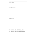
USER MANUAL: BLX-1000 Full Walkthrough Boot Scrubber
READ ALL INSTRUCTIONS BEFORE OPERATING EQUIPMENT
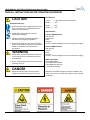
CAUTION
Avoid Personal Injury
1. Avoid contact of cleaning agent with skin and
eyes. If contact occurs, see MSDS sheet for
further first aid measures.
2. Follow safety instructions of chemical
manufacturer (MSDS).
3. Always follow plant and OSHA guidelines
about the use of hygiene equipment.
4. All personnel using this unit must be familiar
with the information contained in this manual.
Follow all installation and maintenance
instructions.
WARNING
5. Always wear appropriate footwear. Secure or
remove loose items on footwear to prevent
entanglement.
6. Ensure solid footing and use both hands when
operating the unit.
DANGER
7. Always disconnect and/or lock out power
supply to unit before cleaning or servicing.
USER MANUAL (MODEL: BLX-1000 REV 103) Page 2 of 15
Specifications:
Frame..............304 stainless steel construction
Width..............96”
Depth..............44”
Height.............55”
Requirements:
Electrical (230V Version):
230 Volts AC
Single Phase
60 Hz
30 Amps
24 VDC - Control Voltage (Unit has internal power supply)
Electrical (480V Version):
480 Volts AC
3 Phase
60 Hz
15 Amps
24 VDC - Control Voltage (Unit has internal power supply)
Water Connection:
Cold Potable Water
35 PSI Minimum Pressure
50 PSI Maximum Pressure
5 GPM Minimum Flow
Attention: A backflow preventer must be installed in the
water line to this unit. Check local codes to ensure proper
installation.
07/30/2014
USER MANUAL: BLX-1000 Full Walkthrough Boot Scrubber
READ ALL INSTRUCTIONS BEFORE OPERATING EQUIPMENT
General Overview
BLX General Maintenance Instructions
The below maintenance procedures are recommended for
normal use. Units which see a high amount of daily use
should be inspected more frequently as necessary.
Weekly:
• Check unit for proper sensor function and brush
rotation.
• Ensure spring loaded grate (if applicable) is
functioning properly.
• Inspect brushes for damage or wear. Check for
missing or deformed bristles.
• Inspect electrical cords and plumbing for damage.
• Inspect and test function of emergency stop
switches.
Monthly:
• Check all fasteners to ensure they are tight.
• Ensure warning labels and decals are present and in
good condition.
• Inspect motors, gearboxes, and reducers for signs of
oil leakage.
• Inspect electrical enclosure for signs of water
intrusion.
• Inspect sensors for damage.
• Inspect moving parts for damage or wear.
Gear Reducer:
• The gear reducer is supplied filled to capacity with
Mobil Cibus SHC 634 NSF H1 Food Grade or equal
synthetic oil. The synthetic lubrication provided with
the reducer is good for ambient temperature ranges
of -10°F to 105°F and is compatible with standard
compounded oil.
• Gear reducer oil should be changed every 2 years or
6000 operating hours, whichever comes first.
• The gear reducer is designed with a bladder type
vent system. This type of vent consists of an internal
bladder that seals the oil chamber from the outside
environment at all times - as pressure builds inside
the unit, the bladder contracts keeping the internal
pressure to a minimum. The advantage to this type
of vent system is that the internal oil chamber is
completely sealed from the outside environment
ensuring that contamination does not enter the
oil chamber or that oil is not released causing
contamination in the application.
Motor:
• Inspect motor(s) at regular intervals. Keep motor(s)
clean and ventilating openings (on TEFC motors)
clear of any obstructions. Double check the
mounting bolts and couplings to ensure that they are
tight and properly adjusted.
• Motor bearings are sealed and not re-greasable.
Bearings should be replaced approximately every 5
years for 8hr/day service.
Quarterly:
• Inspect structure for cracked welds or bent
components.
USER MANUAL (MODEL: BLX-1000 REV 103) Page 3 of 15
07/30/2014
USER MANUAL: BLX-1000 Full Walkthrough Boot Scrubber
READ ALL INSTRUCTIONS BEFORE OPERATING EQUIPMENT
General Overview
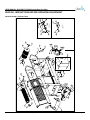
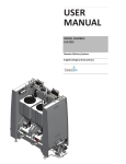
Installation Instructions:
1. Set unit in desired location.
2. Aspects to consider when deciding on placement:
• Room for entering and exiting.
• Traffic flow for unit operation.
• Emergency exit paths or egress in case of
emergency.
• Head room for personnel while using the unit.
• Space to access control box.
• Connections for water and electrical.
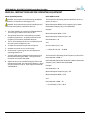
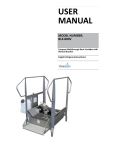
• Refer the the below digram (Figure 3) for unit
placement restrictions.
3. To move the unit use a pallet jack or a hi-lo and lift the
unit from the bottom. To protect the unit, first pad the
forks.
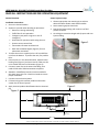
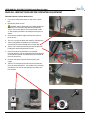
4. Once the unit is in the desired location, adjust the four
leveling feet (Figure 1) and use a level to make sure the
unit is stable and level in all directions (Figure 2).
5. Connect a water line to the water inlet fitting. Unit
needs 35 PSI and a 5GPM connection to operate.
6. Attention: A backflow preventer must be installed in
the water line to this unit. Check local codes to ensure
proper installation.
7. Connect unit to electrical power.
8. Fill chemical jug with sanitizer product and connect
suction line to Venturi injector.
9. Apply chemical product identification label to chemical
jug.
Venturi Injector Setup:
1. Choose appropriate size metering tip to achieve
desired sanitizer dilution ratio stated in MSDS.
2. Screw metering tip into hose barb.
3. Drop end of plastic tubing with strainer into fluid
product container.
4. Cut tubing to convenient length and slip open end over
injector fitting.
Figure 1
Figure 2
Figure 3
6((127(
127()25),;(',167$//$7,216$5($,1)52172)(/(&75,&$/3$1(/0867%(&/($5$7/($67
USER MANUAL (MODEL: BLX-1000 REV 103) Page 4 of 15
81/(6627+(5:,6(63(&,),('
',0(16,216$5(,1,1&+(6
72/(5$1&(6
)5$&7,21$/ $1*8/$50$&+ %(1' 7:23/$&('(&,0$/ 7+5((3/$&('(&,0$/ 7+(,1)250$7,21&217$,1('
,17+,6'5$:,1*,67+(62/(
3523(57<2)&/($1/2*,;
$1<5(352'8&7,21,13$57
25$6$:+2/(:,7+2877+(
:5,77(13(50,66,212)
&/($1/2*,;,6352+,%,7('
0$7(5,$/
'5$:1%<$=,(*(5
),1,6+
'$7(
(55250DWHULDO
:(,*+7/%
(5525:(,*+7
07/30/2014
35235,(7$5<$1'&21),'(17,$/
127('(%855$1'%5($.
$//6+$53('*(6
7,7/(%/;5(9
,7(0180%(5%/;'$)
6&$/(
6+((72)
USER MANUAL: BLX-1000 Full Walkthrough Boot Scrubber
READ ALL INSTRUCTIONS BEFORE OPERATING EQUIPMENT
Operation Instructions:
Shut Down for Maintenance:
Start Up:
To shut down the unit for service or general maintenance:
1. Press the E-STOP switch down on top of the control
box.
2. Disconnect power to unit.
DANGER: Always follow plant and OSHA guidelines
about the use of lock-out tags with the disconnect
switch. The control box has 110 and 220 VAC inside
it. Take proper precautions to avoid personal injury or
death.
3. Shut OFF the sanitizer supply and remove pressure
from the line.
4. The unit is now shut down and ready for service and or
maintenance.
After completed installation of the unit:
1. Ensure the brushes and grate are properly secured in
their correct positions.
2. Turn ON sanitizing solution and water.
3. Pull the E-STOP switch up and watch for the light on
the switch to signal that the unit has power.
4. Wait for 10 seconds for unit to start up completely.
5. The unit is now ready for activation using the sensor.
6. Before placing footwear into the unit, test that the unit
is working properly by activating the sensor.
Operation:
Before beginning unit operation, ensure solid footing and
use both hands when operating the unit.
1. To begin unit operation, step onto the grate.
2. The grate will push down on the springs, activating the
prox sensor below, which will turn on the brushes for a
set period of time.
3. Walk through the unit and allow the rotating brushes
to clean by slowly moving the boot, so every part of
the boot contacts the brushes.
4. The spray bar below the grate will spray sanitizer
solution onto the brushes, which will then be applied
to the boots.
5. Once the boots are clean, step through the unit.
6. If boots are extremely dirty, it may be necessary to
perform second cleaning.
WARNING: Always wear appropriate footwear.
Secure or remove loose items on footwear to prevent
entanglement.
WARNING: All personnel using this unit must be
familiar with the information contained in the user
manual. Follow all installation and maintenance
instructions.
WARNING: Use only for intended use as described in
this manual.
WARNING: Always follow safety precautions and obey
warning labels. Failure to do so could result in injury
or death.
USER MANUAL (MODEL: BLX-1000 REV 103) Page 5 of 15
Shut Down for Cleaning/Washdown:
1. To shut down the unit for cleaning, press the E-STOP
switch on top of the control box.
2. Disconnect power to unit.
DANGER: Always follow plant and OSHA guidelines
about the use of lock-out tags with the disconnect
switch. The control box has 110 and 220 VAC inside
it. Take proper precautions to avoid personal injury or
death.
Cleaning/Washdown:
1. Once the unit is properly shut down, it is safe to clean
the unit.
2. Lift the grate up.
3. Lift the brush assembly out of the tub.
4. The brushes can be disassembled from the assembly
by pulling apart and washed individually in a COP
tank or wash machine, and the tub can be washed by
conventional means.
CAUTION: Use of high pressure above 400 PSI is not
recommended on sensitive areas such as electrical
components, the motors, or the attached gearboxes.
07/30/2014
USER MANUAL: BLX-1000 Full Walkthrough Boot Scrubber
READ ALL INSTRUCTIONS BEFORE OPERATING EQUIPMENT
Motor Speed Adjustment:
Brush RPM Formula:
DANGER: Do not open control box during washdown
conditions or if someone is cleaning the unit.
The formula for calculating Speed in RPM from Drive Frequency in Hertz is:
DANGER: Only authorized personnel should open the
control box while power is applied to the unit.
Motor Nameplate RPM X Drive Frequency (Hz) / Motor
Nameplate Frequency (Hz) / Gear Reduction
1. The motor defaults at a speed of 1750 RPM at 60 Hz.
The worm gear reducer has a ratio of 20:1.
2. The speed of the motor is controlled by a variable
frequency motor drive. As the drive decreases the
frequency of the motor, the RPMs decrease.
3. The V.F. drive displays the Hz. on a small display and
the knob next to it adjusts the Hz.
4. To adjust the speed, first open the control box.
5. Activate the sensor to turn on the motor.
6. As the motor is spinning, the unit will display the
operating speed in Hz.
7. Turn the knob counter-clockwise to decrease the Hz,
therefore decreasing the RPMs. Turning the knob
clockwise will increase the RPMs.
8. Adjust the Hz. on the variable frequency drive to the
desired brush speed. The minimum frequency is 30 Hz
and the maximum is 60 Hz Clean-Logix recommends
70 RPM/48 Hz.
Example:
Motor Nameplate RPM = 1750
Motor Nameplate Frequency (Hz) = 60
Gear Reduction = 20
and
Drive Frequency (Hz) = 48
--> 1750 X 48 / 60 /20 = 70 RPM
The formula for calculating Drive Frequency in Hertz from
Desired Speed in RPM is:
Desired Speed RPM X Gear Reduction X Motor Nameplate
Frequency (Hz) / Motor Nameplate RPM
Example:
Gear Reduction = 20
Motor Nameplate Frequency (Hz) = 60
Motor Nameplate RPM = 1750
and
Desired Speed in RPM = 70
--> 70 X 20 X 60 / 1750 = 48 Hz
USER MANUAL (MODEL: BLX-1000 REV 103) Page 6 of 15
07/30/2014
USER MANUAL: BLX-1000 Full Walkthrough Boot Scrubber
READ ALL INSTRUCTIONS BEFORE OPERATING EQUIPMENT
Drive Parameter Settings:
Allen Bradley 4M Variable Frequency Drive
Timer Setting:
Schneider Magnecraft 821TD10H-UNI Timer
DANGER: Do not open control box during washdown
conditions or if someone is cleaning the unit.
1. Function D “Off Delay” (S Break)
DANGER: Only authorized personnel should open the
control box while power is applied to the unit.
Parameter Number
P102
P104
P105
P106
P109
P110
t201
t221
Description
Motor NP Hertz
Minimum Freq
Maximum Freq
Start Source
Accel Time
Decel Time
Digital In1 Sel
Relay Out Sel
Setting
60
30
60
2
1
2
3
1
Units
Hz
Hz
Hz
N/A
s
s
N/A
N/A
2. Time range: 1-10 seconds
3. Setting: 1 second
Venturi Setting:
1. Turn adjustment screw clockwise until it stops.
2. Turn adjustment screw counter clockwise
3-1/2 full turns.
Motor Overload Sensor Setting:
Automation Direct ACS-200 Current Switch
1. 1-6A Setting (Jumper Removed)
2. Two loops of wire through sensor.
3. Turn trimpot counterclockwise for at least 5 turns.
4. Turn trimpot clockwise for 3-1/2 turns.
5. Test and adjust accordingly in 1/8 turn increments.
USER MANUAL (MODEL: BLX-1000 REV 103) Page 7 of 15
07/30/2014
USER MANUAL (MODEL: BLX-1000 REV 103) Page 8 of 15
$
%
(5525:(,*+7
(55250DWHULDO
:(,*+7/%
),1,6+
0$7(5,$/
',0(16,216$5(,1,1&+(6
72/(5$1&(6
)5$&7,21$/ $1*8/$50$&+ %(1' 7:23/$&('(&,0$/ 7+5((3/$&('(&,0$/ 81/(6627+(5:,6(63(&,),('
127('(%855$1'%5($.
$//6+$53('*(6
'$7(
'5$:1%<$=,(*(5
7+(,1)250$7,21&217$,1('
,17+,6'5$:,1*,67+(62/(
3523(57<2)&/($1/2*,;
$1<5(352'8&7,21,13$57
25$6$:+2/(:,7+2877+(
:5,77(13(50,66,212)
&/($1/2*,;,6352+,%,7('
35235,(7$5<$1'&21),'(17,$/
'(7$,/%
6&$/(
'(7$,/$
6&$/(
6&$/(
6+((72)
,7(0180%(5%/;'$)(;3/2'('
7,7/(%/;5(9
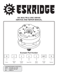
Model: BLX-1000 | Exploded View
USER MANUAL: BLX-1000 Full Walkthrough Boot Scrubber
READ ALL INSTRUCTIONS BEFORE OPERATING EQUIPMENT
07/30/2014
USER MANUAL: BLX-1000 Full Walkthrough Boot Scrubber
READ ALL INSTRUCTIONS BEFORE OPERATING EQUIPMENT
Model: BLX-1000 | Parts Callout
12
3$57180%(5
)
67$1'2));;66
'(6&5,37,21
)
%2/76+&6;66
)
1871</2&.66
)
1871</2&.66
)
1871</2&.66
)
:$6+(5667<3($
)
:$6+(5667<3($
)
:$6+(5;;8+0:
)
67$1'2));;66
47<
)
%2/7++&;66
)
:$6+(5)(1'(566
)
%2/7++&;66
)
%2/7++&;66
)
%2/7++&;66
)
%2/7++&;66
)
.(<;;66
)
67$1'2));;66
)
%2/76+877(5;66
)
187+(;66
)
6&5(:;663+,//,363$1+'
0
660272502817833(5
0
+22.67(3:(/'0(17
0
*5$7(:(/'0(17%/;
0
78%:(/'0(17%/;'$)
0
+25,=217$/%586+%/;
0
/21*635$<32/(%/;
0
*5$7(635,1*$66(0%/<
0
62/(12,'%5$&.(7
0
'5,9(6+$)702725%586+:(/'0(17
0
&20%,1$7,21%586+$66(0%/<
0
660272502817%/;
0
635$<32/(&20%2%586+%/;
0
*5$7(/$7&+
0
-8*+22.:(/'0(17
0
660272502817%/;
0
(/(&75,&$/$66<%/;6%;
0
%586+6833257:(/'0(17
3
02725+353066&
3
02725+353066&
3
*($55('8&(566
3
62/(12,'66
3
9(1785,,1-(&72566
3
3,3(%86+,1*;66
3
3,3(7((66
3
3,3((/%2:675((766
3
3,3(&$366
3
352;,0,7<6(1625PP
3
3,3(+(;1,33/(66
3
&25'*5,3137;1</
3
&25'*5,31871361</
3
&25'*5,3137;1</21
3
62/(12,'&$%/(PP',19
3
3,3(&283/(5
3
48,&.),7137;78%(
3
/$%(/3,1&+32,17+$=$5'
3
/$%(/029,1*3$576
3
/$%(/127,&(%/;
3
/$%(/6/,3+$=$5'
3
(0(5*(1&<672381,7
3
&$%/(032/(P,3.
USER MANUAL (MODEL: BLX-1000 REV 103) Page 9 of 15
07/30/2014
USER MANUAL: BLX-1000 Full Walkthrough Boot Scrubber
READ ALL INSTRUCTIONS BEFORE OPERATING EQUIPMENT
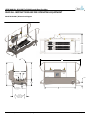
Model: BLX-1000 | Dimensions Diagram
/(*6$5(
$'-867$%/(
81/(6627+(5:,6(63(&,),('
',0(16,216$5(,1,1&+(6
72/(5$1&(6
)5$&7,21$/ $1*8/$50$&+ %(1' 7:23/$&('(&,0$/ 7+5((3/$&('(&,0$/ 2
$//:,7+027256
$1'(/(&%2;
5(029('
'5$:1%<$=,(*(5
'$7(
(5525:(,*+7
',0(16,216$5(,1,1&+(6
72/(5$1&(6
)5$&7,21$/ $1*8/$50$&+ %(1' 7:23/$&('(&,0$/ 7+5((3/$&('(&,0$/ 2
$//:,7+027256
$1'(/(&%2;
5(029('
'5$:1%<$=,(*(5
'$7(
(5525:(,*+7
USER MANUAL (MODEL: BLX-1000 REV 103) Page 10 of 15
7+(,1)250$7,21&217$,1('
,17+,6'5$:,1*,67+(62/(
3523(57<2)&/($1/2*,;
$1<5(352'8&7,21,13$57
25$6$:+2/(:,7+2877+(
:5,77(13(50,66,212)
&/($1/2*,;,6352+,%,7('
0$7(5,$/
:(,*+7/%
35235,(7$5<$1'&21),'(17,$/
),1,6+
(55250DWHULDO
127('(%855$1'%5($.
$//6+$53('*(6
81/(6627+(5:,6(63(&,),('
0$7(5,$/
(55250DWHULDO
7+(,1)250$7,21&217$,1('
,17+,6'5$:,1*,67+(62/(
3523(57<2)&/($1/2*,;
$1<5(352'8&7,21,13$57
25$6$:+2/(:,7+2877+(
:5,77(13(50,66,212)
&/($1/2*,;,6352+,%,7('
),1,6+
:(,*+7/%
/(*6$5(
$'-867$%/(
35235,(7$5<$1'&21),'(17,$/
127('(%855$1'%5($.
$//6+$53('*(6
7,7/(%/;5(9
,7(0180%(5%/;'$)
6&$/(
6+((72)
07/30/2014
7,7/(%/;
,7(0180%(5
6&$/(
/(*(1'
(6
6
9'&
/
6
(6
9'&
0&6
6
675,*
6
$
66
77,0(5
07/30/2014
5
$
6
5
6
9)'
57
7
57
7
7
7
0
02725
+3
9)/$
0
0&6
7
&855(176(1625
02725
:,5(08673$66
7
7+528*+/223 +3
7:,&(
9)/$
7
0&6
/
&855(176(1625
:,5(08673$66
/
7+528*+/223
7:,&(
/
5
5
9)'
57
7
57
7
7
7
0
6
&20
9'&
0&6
6
6
6
&20
9'&
*
3/32:(521
,1',&$725/,*+7
0&
*
3/32:(521
,1',&$725/,*+7
62/
62/87,21
62/(12,'
62/
62/87,21
62/(12,'
0&6
/
02725
+3
9)/$
02725
+3
9)/$
0
0&6
7
&855(176(1625
:,5(08673$66
7
7+528*+/223
7:,&(
7
0&6 /
&855(176(1625
:,5(08673$66
/
7+528*+/223
7:,&(
72548(
32:(5LQOE
&21752/LQOE
&&8:,5(21/<
72548(
32:(5LQOE
&21752/LQOE
&&8:,5(21/<
6
7
7
/
/
7
/
9)'
/
ġ
ġ
ġ
/
5
5
9)'
/
57
7
57
/
9)'
0
7
02725
+3
9)/$
0
0&6
7
&855(176(1625
:,5(08673$66
7+528*+0/223
7
7:,&(
6
02725
+3
9)/$
72548(
32:(5LQOE
&21752/LQOE
&&8:,5(21/<
72548(
32:(5LQOE
&21752/LQOE
&&8:,5(21/<
7
7
7 7
7
0
6
/
7
0&6
&855(176(1625
:,5(08673$66
7+528*+0/223
7:,&(
:(,*+7/%
127('(%855$1'%5($.
$//6+$53('*(6
6&$/(
,7(0180%(50
6+((72)
0&
ġ
35235,(7$5<$1'&21),'(17,$/
ġ
6
ġ
7+(,1)250$7,21&217$,1('
',0(16,216$5(,1,1&+(6
,17+,6'5$:,1*,67+(62/(
72/(5$1&(6
3523(57<2)&/($1/2*,;
81/(6627+(5:,6(63(&,),('
35235,(7$5<$1'&21),'(17,$/
)5$&7,21$/ $1<5(352'8&7,21,13$57
25$6$:+2/(:,7+2877+(
$1*8/$50$&+ %(1'7+(,1)250$7,21&217$,1('
',0(16,216$5(,1,1&+(6
:5,77(13(50,66,212)
,17+,6'5$:,1*,67+(62/(
7:23/$&('(&,0$/
72/(5$1&(6
&/($1/2*,;,6352+,%,7('
3523(57<2)&/($1/2*,;
7+5((3/$&('(&,0$/
)5$&7,21$/
$1<5(352'8&7,21,13$57
25$6$:+2/(:,7+2877+(
$1*8/$50$&+
%(1' 0$7(5,$/
'5$:1%<$=,(*(5
:5,77(13(50,66,212)
7:23/$&('(&,0$/
0DWHULDOQRWVSHFLILHG!
7,7/((/(&75,&$/$66<%/;6%;5(9
&/($1/2*,;,6352+,%,7('
7+5((3/$&('(&,0$/ '$7(
),1,6+
0$7(5,$/
'5$:1%<$=,(*(5
,7(0180%(5
127('(%855$1'%5($.
0DWHULDOQRWVSHFLILHG!
:(,*+7/%
7,7/((/(&75,&$/$66<%/;6%;5(9
$//6+$53('*(6
'$7(
),1,6+
6&$/(
6+((72)
81/(6627+(5:,6(63(&,),('
&20
9'&
0&6
&20
9'&
0&6
6
72548(
32:(5LQOE
&21752/LQOE
&&8:,5(21/<
72548(
32:(5LQOE
&21752/LQOE
&&8:,5(21/<
6
7
7
/
/
7
/
9)'
/
0&6
/
$
72548(LQOE0$;
&&8:,5(21/<
$
75,*
77,0(5
72548(LQOE0$;
&&8:,5(21/<
&20
&20
72548(LQOE
&&8:,5(21/<
0&6
0&6
0&6 0&60&6 0&6
&855(17 &855(17 &855(17
72548(LQOE
6(1625 6(1625
6(1625
&&8:,5(21/<
,1',&$7(6),(/':,5,1*
,1',&$7(60(&+$1,&$//,1.$*(
6
(6
0&6
0&6
0&6
0&6
&855(17 &855(17 &855(17
6(1625 6(1625 6(1625
/
,1',&$7(6),(/':,5,1*
,1',&$7(60(&+$1,&$//,1.$*(
/(*(1'
(6
36
67$57
6(1625
9'&
36
67$57
6(1625
9'&
/
/
369'&/
32:(56833/<
72548(LQOE
&8:,5(21/<
369'&
32:(56833/<
/
/
72548(LQOE
&8:,5(21/<
/
/
/
/
/
/
/
/
/
0&6
/
0&6
72548(LQOE
&&8:,5(21/<
&%
0&
$
72548(LQOE
&&8:,5(21/<
/
/
0&
0&6
&20
&20
0&6
&20
&20
USER MANUAL (MODEL: BLX-1000 REV 103) Page 11 of 15
&20
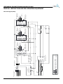
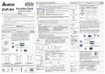
Electrical Diagram (230V):
&20
93+$+]
&,5&8,75(48,5('
'225
',6&
93+$+]
&,5&8,75(48,5('
/ '225
&%
',6&
$
/
USER MANUAL: BLX-1000 Full Walkthrough Boot Scrubber
READ ALL INSTRUCTIONS BEFORE OPERATING EQUIPMENT
/
/
369'&
32:(56833/<
(6
(6
6
9'&
(6
6
/
6
0&6
0&6
0&6
6
$
6
07/30/2014
6
5
$
72548(LQOE0$;
&&8:,5(21/<
$
6
77,0(5
$
6
6
75,*
77,0(5
0&6
72548(LQOE0$;
&&8:,5(21/<
&20
&20
72548(LQOE
&&8:,5(21/<
75,*
5
5
7
9)'
7
5
7
/ /
/
0
02725
+3
93+)/$
/
5
5
81/(6627+(5:,6(63(&,),('
7
7
7
6
&20
9'&
0&6
6
6
6
&20
9'&
0&6
*
:(,*+7/%
0$7(5,$/
:(,*+7/%
0DWHULDOQRWVSHFLILHG!
),1,6+
$//6+$53('*(6
127('(%855$1'%5($.
$//6+$53('*(6
5
5
ġ
ġ
ġ
7
5
7
5
7
/
9)'
/
6
/
7
7
7
6
02725
+3
9)/$
02725
+3
72548(
93+)/$
32:(5LQOE
&21752/LQOE
&&8:,5(21/<
0
0
0&6
7
&855(176(1625
:,5(08673$66
7
7+528*+0/223
7:,&(
7
0&6
&855(176(1625
:,5(08673$66
7+528*+0/223
7:,&(
72548(
32:(5LQOE
&21752/LQOE
&&8:,5(21/<
7
7
7
6&$/(
,7(0180%(50
6&$/(
6+((72)
6+((72)
,7(0180%(50
7,7/((/(&75,&$/$66<%/;5(9
'5$:1%<$=,(*(5
127('(%855$1'%5($.
'$7(
/
/
9)'
7,7/((/(&75,&$/$66<%/;6%;5(9
ġ
ġ
ġ
0&
*
3/32:(521
,1',&$725/,*+7
3/32:(521
,1',&$725/,*+7
62/
62/87,21
62/(12,'
62/
62/87,21
62/(12,'
72548(
32:(5LQOE
&21752/LQOE
&&8:,5(21/<
0
0
/
/
02725
+3
9)/$
02725
+3
93+)/$
72548(
32:(5LQOE
&21752/LQOE
&&8:,5(21/<
6
7
7
7
0&6
&855(176(1625
:,5(08673$66
7
7+528*+/223
7:,&(
7
/
0&6 /
&855(176(1625
/
:,5(08673$66
7+528*+/223
7:,&(
0&
35235,(7$5<$1'&21),'(17,$/
9)'
7
5
7
5
7
/ /
/
7
/
9)'
6
7+(,1)250$7,21&217$,1('
',0(16,216$5(,1,1&+(6
,17+,6'5$:,1*,67+(62/(
72/(5$1&(6
3523(57<2)&/($1/2*,;
81/(6627+(5:,6(63(&,),('
)5$&7,21$/ 35235,(7$5<$1'&21),'(17,$/
$1<5(352'8&7,21,13$57
25$6$:+2/(:,7+2877+(
$1*8/$50$&+ %(1'7+(,1)250$7,21&217$,1('
',0(16,216$5(,1,1&+(6
:5,77(13(50,66,212)
7:23/$&('(&,0$/ ,17+,6'5$:,1*,67+(62/(
&/($1/2*,;,6352+,%,7('
72/(5$1&(6
3523(57<2)&/($1/2*,;
7+5((3/$&('(&,0$/ )5$&7,21$/ $1<5(352'8&7,21,13$57
0$7(5,$/
25$6$:+2/(:,7+2877+(
'5$:1%<$=,(*(5
$1*8/$50$&+
%(1' :5,77(13(50,66,212)
7:23/$&('(&,0$/
0DWHULDOQRWVSHFLILHG!
&/($1/2*,;,6352+,%,7('
'$7(
7+5((3/$&('(&,0$/
),1,6+
&20
&20
9'&
0&6
9'&
0&6
6
0
72548(
32:(5LQOE
&21752/LQOE
&&8:,5(21/<
7
7
7
0&6
&855(176(1625
02725
7
:,5(08673$66 +3
7+528*+/223
9)/$
7
7:,&(
7
/
/
&855(176(1625
/
:,5(08673$66
7+528*+/223
7:,&(
72548(
32:(5LQOE
&21752/LQOE
&&8:,5(21/<
6
7
7
/
7
/
9)'
0&6
0&6
0&6
&855(17 &855(17 &855(17
6(1625 6(1625 6(1625
0&6
0&6
0&6
&855(17 &855(17
&855(17
72548(LQOE
6(1625 6(1625
6(1625
&&8:,5(21/<
/
0&6
,1',&$7(6),(/':,5,1*
,1',&$7(60(&+$1,&$//,1.$*(
6
(6
9'&
/
/
/
/
72548(LQOE
&&8:,5(21/<
/
/
,1',&$7(6),(/':,5,1*
,1',&$7(60(&+$1,&$//,1.$*(
/(*(1'
/(*(1'
72548(LQOE
&8:,5(21/<
36
67$57
6(1625
9'&
/
/
/
/
/
/
369'&
/
32:(56833/<
72548(LQOE
/
&8:,5(21/<
36
67$57
6(1625
9'&
/
/
93+$+]
&,5&8,75(48,5('
/
/
0&
/
0&6
/
/
0&6
0&6
72548(LQOE
&&8:,5(21/<
0&
0&6
&%
$
0&6
&20
&20
0&6
&20
&20
USER MANUAL (MODEL: BLX-1000 REV 103) Page 12 of 15
&20
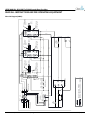
Electrical Diagram (480V):
&20
93+$+]
&,5&8,75(48,5('
'225
',6&
'225
&%
',6&
$
/
/
USER MANUAL: BLX-1000 Full Walkthrough Boot Scrubber
READ ALL INSTRUCTIONS BEFORE OPERATING EQUIPMENT
USER MANUAL: BLX-1000 Full Walkthrough Boot Scrubber
READ ALL INSTRUCTIONS BEFORE OPERATING EQUIPMENT
Troubleshooting Instructions:
Unit will not operate and E-STOP is not illuminated:
• Make sure that the unit is plugged in.
• Verify the E-STOP is not pushed down.
• Verify that there is main power going to the unit.
• Verify the circuit breakers in the building have not
been tripped.
Unit will not operate and E-STOP is illuminated.
• Check that the sensor is operating properly.
• Make sure all physical connections to the brushes
are in place.
• Restart unit by pushing down the E-STOP, waiting 10
seconds, then turning the unit on again.
Unit will not spray:
• Check that water line is attached, reads at least 35
PSI, and is turned on.
• Check spray bar and make sure the holes are not
clogged with debris.
• Check that the water and sanitizer connections to
the solenoid are firmly in place.
• Check that chemical jug has liquid in it.
Unit is leaking onto floor:
• Check to make sure all joints are sealed.
USER MANUAL (MODEL: BLX-1000 REV 103) Page 13 of 15
07/30/2014
USER MANUAL: BLX-1000 Full Walkthrough Boot Scrubber
READ ALL INSTRUCTIONS BEFORE OPERATING EQUIPMENT
Solenoid & Venturi Injector Maintenance:
1. Press the E-STOP switch down on top of the control
box.
2. Disconnect power to unit.
DANGER: Always follow plant and OSHA guidelines
about the use of lock-out tags with the disconnect
switch. The control box has 110 and 220 VAC inside
it. Take proper precautions to avoid personal injury or
death.
3. Shut OFF the sanitizer supply and remove pressure
from the line.
4. The unit is now shut down and ready for maintenance.
5. Take a small phillips screwdriver to remove the
connection from the solenoid to the control box.
6. Take a 7/16” socket wrench and remove the locknuts
holding the solenoid bracket to the unit.
7. Once the locknuts and washers are removed
from the bracket, pull the assembly away from the unit
so the Venturi injector and solenoid can be twisted off
from the spray bars.
8. Unscrew the Venturi injector from the 3/8” pipe
nipple.
9. Take a 1/4” socket wrench and remove the solenoid
from the solenoid bracket. The insides of the solenoid
and Venturi can now be accessed and any debris can
be removed.
USER MANUAL (MODEL: BLX-1000 REV 103) Page 14 of 15
07/30/2014
7
07/30/2014
5
3
USER MANUAL (MODEL: BLX-1000 REV 103) Page 15 of 15
5
103
8
6
23 13/16"
7
2
5
3
1
103
11
4
5
12"
4
6
23 13/16"
7
2
1
103
11
103
3
2
1
DATE
F1148
F1056
F1047
42
7
7
2
9
1
2
1
1
M1231
3
ERROR!:WEIGHT
WEIGHT (LB.)
4
103
10
103
10
2
3 DEBURR AND BREAK
NOTE:
ALL SHARP EDGES!
SCALE: 1:12
ITEM NUMBER:
2
M1186
1
SHEET 1 OF 1
1
DRAWN BY: A. ZIEGER
ITEM NUMBER: M1186
NOTE: DEBURR AND BREAK
ERROR!:MaterialWEIGHT (LB.)
ALL SHARP
EDGES! COMBO BRSH ASSY BLX-800 REV103
TITLE:
SCALE: 1:12
SHEET 1 OF 1
DATE: 5/28/2014
ERROR!:WEIGHT
MATERIAL
FINISH
1
2
3
1
1
3
1
1
1
1
4
2
2
4
8
16
12
QTY.
TITLE: COMBO BRSH ASSY BLX-800 REV103
2
7
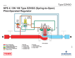
COMBO BRUSH BAR
BRUSHBRUSH
BAR COUPLER 3
10COMBO
M1179
11
OR AS A WHOLE WITHOUT THE
ANGULAR: MACH .5 BEND
2
MATERIAL
DRAWN BY: A. ZIEGER
WRITTEN PERMISSION OF
TWO PLACE DECIMAL
.015"
ERROR!:Material
CLEAN-LOGIX IS PROHIBITED.
THREE PLACE DECIMAL
.005"
DATE: 5/28/2014
FINISH
BRUSH COUPLER 1
BRUSH COUPLER 2
BRUSH COUPLER 3
7
M1177
M1178
8
1
9
BRUSH COUPLER 2
PROPRIETARY AND CONFIDENTIAL!
2
M1231
11
6
M1179
10
UNLESS OTHERWISE SPECIFIED:
9
7
6
M1178
9
THE INFORMATION CONTAINED
DIMENSIONS ARE IN INCHES
IN THIS DRAWING IS THE SOLE
UNLESS OTHERWISE SPECIFIED:
PROPRIETARY AND CONFIDENTIAL!
TOLERANCES:
PROPERTY OF CLEAN-LOGIX.
FRACTIONAL
1/16"
ANY REPRODUCTION IN PART
THE
INFORMATION
CONTAINED
DIMENSIONS ARE IN INCHES ANGULAR: MACH .5 BEND 2
OR AS A WHOLE WITHOUT THE
IN THIS DRAWING IS THE SOLE
WRITTEN PERMISSION OF
TOLERANCES:
TWO PLACEPROPERTY
DECIMAL OF .015"
CLEAN-LOGIX.
CLEAN-LOGIX IS PROHIBITED.
FRACTIONAL 1/16"
THREE PLACE
DECIMAL
.005"
ANY
REPRODUCTION
IN PART
12"
1
SIDE DISK BRUSH 12" DIA.
M1101
BRUSH COUPLER 1
M1177
8
7
4
HORIZONTAL BRUSH 8" DIA. X 6" WIDE
M1101
7
M1026
5 SIDE DISK
F1150BRUSH
PIN12"
DOWEL
DIA. 1/4 X 1-1/2 SS
6
2
4 HORIZONTAL
F1149
BOLT SHC
1/4-20
X 3-1/2
BRUSH
8" DIA.
X 6"
WIDESS
2
X 1-1/2
3 PIN DOWEL
F1148 1/4BOLT
SHC SS
1/4-20 X 2-1/2 SS
4
M1026
F1150
NUT NYLOCK 1/4-20 SS
8
16
12
QTY.
6
5
F1047
SHC 1/4-20
X 3-1/2
2 BOLT F1056
WASHER
1/4SSSS TYPE A
1
BOLT SHC 1/4-20 X 2-1/2 SS
WASHER 1/4 SS TYPE A
NO. PART NUMBER DESCRIPTION
NUT NYLOCK 1/4-20 SS
NO. PART NUMBER DESCRIPTION
UPDATED M1177 AND M1179 TO REV102, UPDATED
M1231 TO REV101. M1231 REV101 IS LONGER THAN THE
F1149
4 5/28/2014
PREVIOUS REVISION
DESCRIPTION
REVISIONS
5/28/2014
UPDATED M1177 AND M1179 TO REV102, UPDATED
M1231 TO REV101. M1231 REV101 IS LONGER THAN THE
PREVIOUS REVISION
103
REV.
DATE
REVISIONS
DESCRIPTION
REV.
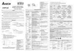
USER MANUAL: BLX-1000 Full Walkthrough Boot Scrubber
READ ALL INSTRUCTIONS BEFORE OPERATING EQUIPMENT
Model: M1186 Combo Brush Assembly | Parts Callout