1
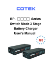
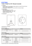
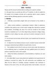
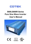
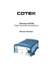
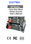
User Guide For CR-16 Remote Control
1. Features
z
z
z
z
z
Battery bank voltage display
Output power display
Error condition indicator High Battery, Low Battery, Over Temperature, Over Load conditions
Action condition indicator INV, GRID, POWER SAVING, CHARGING STATUS
Connection failure notification
2. Specification
Input Voltage : 10.5 ~ 66 Vdc
Operating Temperature Range : 0 ~ 40
Storage Temperature Range : - 30
~ 70
Stand-By Current Draw : < 80mA
Applicable Models : SP series – 700 / 1000 / 1500 / 2000 / 3000 / 4000
SL series – 2000 / 3000
* Note Grid LED is only functional when connecting SP series with TR-40.
z
z
z
z
z
3. Introduction
3-1. Front Panel Introduction
Fig.1 Front Panel Introduction
M Power ON/OFF Button
N Charging Status LED
O Output power indicator
P
Q
Battery voltage indicator
Other Indicators
M Power ON/OFF Button
Power ON/OFF button is to turn the inverter on or off.
N Charging Status LED (BULK / ABSORPTION / FLOAT) shows the charging status: (Only applicable to
SL series)
x BULK: When the battery is in low voltage status, the battery is charged at constant current by
maximum charge current.
x ABSORPTION: When the battery is near fully charged, the battery keeps charging by constant
voltage mode.
x FLOAT: When the battery is fully charged, this state maintains the battery at 100% charge without
overcharging or damaging the battery.
Please refer to the detail information in SL series user manual accordingly.
1
O Output power indicator
Output power indicator shows the power draw from the power inverter by the load. Ideally, the output
power indicator should remain in the green & orange area of the bar chart.
If the output power indicator is up to the red area, the OLP LED will flash and the inverter will shut down.
P Battery voltage indicator
Battery voltage indicator will move up and down as the battery voltage changes. Ideally, the voltage
should remain in the green area of the bar chart. If the voltage goes into the red area at the top and
bottom of the bar chart, inverter may shut down.
Q Other Indicators
z OVP (Over voltage protection indicator)
It indicates that the power inverter shuts down because its input voltage is above limit voltage.
z UVP (Under voltage protection indicator)
The under voltage indicator is to indicate the inverter shut down due to under voltage protection.
z OLP (Overload protection indicator)
The overload indicator is to indicate the inverter shut down due to short circuit or overload protection.
z OTP (Over temperature protection indicator)
The over temp indicator is to indicate the inverter shut down due to over temperature protection.
Once the inverter cools down, the indicator will turn off automatically.
z INV. indicator
The INV. indicator is to indicate the inverter is ready.
z PWR.SAV. Indicator
LED
Solid
Flashing
Off
Power saving functions are described below
Meaning
Inverter Output
Ready
ON
Active
OFF
Inactive
z GRID indicator
The GRID indicator is to indicate the AC Grid is connected to inverter.
(For SP series: Only functional when connecting SP Series with TR-40)
z CHG indicator
The CHG indicator is to indicate the battery charging status (Only applicable to SL series).
3-2. Rear Panel Introduction
Fig.2
Rear Panel Introduction
Fig.3
Aux Connector
h Aux port
The connector (Fig.3) connected to AUX wire (AWG 14 or 16) must connected with 12V / 0.5A fuse.
2
z Ignition Lockout function – The ignition lockout function is to turn OFF the Inverter when the auxiliary
input wiring is connected to the ACC with 12 Volts.
z Return Override Function – The Return Override Function is to turn ON the inverter when the auxiliary
input wiring is connected to the reversed gear shift with 12 Volts.
i Phone Jack Connector
1. Before connection, please make sure to switch the inverter to REMO position. (For SP series) (Fig.4)
2. Connect the RJ-11 cable between CR-16 remote and the inverter.
Fig.4
Phone Jack Connector
WARNING!
DO NOT use standard telephone cable.
j JP1 The JP1 is to set either Return Override Function or Ignition lockout function.
z JP1 jumper “Short” - Return Override Function
Return Override Function – The Return Override Function is to turn ON the inverter when the
auxiliary input wiring is connected to the reversed gear shift with 12 Volts.
z JP1 jumper “Open” – Ignition Lockout Function
Ignition Lockout function – The ignition lockout function is to turn OFF the inverter when the auxiliary
input wiring is connected to the ACC with 12 Volts.
z The connector which is connected to AUX power must use with 12V / 0.5A fuse.
Trigged signal
AUX
1
JP1
Inverter
Status
Open
OFF
0
Open
ON
1
Short
ON
0
Short
OFF
Note default mode is Open.
Fig.5
SP series remote position
No.33, Sec. 2, Renhe Rd., Daxi Dist., Taoyuan City 33548, Taiwan
Phone +886-3-3891999
FAX +886-3-3802333
http // www.cotek.com.tw
2015.10._A0
3