1
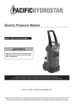
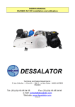
Installation and User Manual
Residential Reverse Osmosis Water Filter
Systems
QuaRO
Wasserhaus Deutschland GmbH· Max-Wundel-Strasse 12 · D-14469 Potsdam ·
Tel. 0331 – 505 79 43 · Fax 0331 – 505 79 52
www.wasserhaus.de · e-mail: [email protected]
page 1
Thank you for choosing Wasserhaus to buy a Residential Reverse Osmosis Water System.
You now own a water filtration system that will effectively remove many contaminants and
unwanted taste and odour from the water supply.
This system uses household water pressure to reverse a natural physical process called
osmosis. Water, under pressure, is forced through a semi-permeable membrane where
minerals and impurities are filtered out. Clean drinking water goes to the faucet or storage,
while the impurities are sent to the drain. These impurities are measured in the water as total
dissolved solids (TDS).
The system includes standard, 10 inch, replaceable pre and post filter cartridges. The prefilters remove sediment and chlorine from the water supply before they can enter the RO
membrane. The post-filter removes any taste or odours that may remain in the water after
passing through the RO membrane, and just before going to the RO faucet. To prevent water
waste, an automatic shut-off valve closes when the RO faucet is closed and the storage tank
is full.
This reverse osmosis system will provide you with a continuous supply of clear, delicious
water for drinking, cooking and other uses. Foods will look and taste better, too. Having high
quality RO water at your fingertips eliminates the need to buy bottled water. The storage tank
holds up to 4 gallons* of RO water for your needs.
Read carefully the following instructions before preparing your tools and proceeding with the
actual installation. Failure to do so could result in personal injury or damage to the equipment
or other property.
For questions please, don’t hesitate to contact your dealer.
We wish you best taste with your WASSERHAUS RO water filter system.
Wasserhaus Deutschland GmbH· Max-Wundel-Strasse 12 · D-14469 Potsdam ·
Tel. 0331 – 505 79 43 · Fax 0331 – 505 79 52
www.wasserhaus.de · e-mail: [email protected]
page 2
* standard RO systems might be equipped with either 2, 3.2 or 4 gal. storage tanks
Important Information!
Installation of the Water Treatment System requires the use of the common tools. If
you are not familiar with the use of tools, we advise to hire a plumber or other
qualified persons to install the system. Follow all local and state plumbing codes.
The R/O System is prepared for under the sink application and must be installed to the cold
water supply only. Do not connect to hot water. The system operates on water temperature
of 40°F./4°C. min - 100°F./38°C. max. Temperatures below the minimum will freeze and
crack the R/O membrane and filter housings. Above 100°F./38°C., the membrane will rapidly
deteriorate.
The quality, temperature and pressure of the water must meet the following standards:
WARNING : Do not connect HOT water source to this unit.
WARNING : Incorrect installation will VOID the warranty.
IMPORTANT: Always close cold water feeder valve if system is not observed in order to
avoid water damages in case the RO unit or the water supply is leaking. We recommend you
to install a water alarm system at the cold water supply in order to detect when your RO unit
is leaking. A water alarm system can shut your cold water supply to the system if it detects
water outside the RO system. You can order a water alarm system from our shop: Item No
18599.
System Specification
Dimensions
Height
Width
RO-5, RO-6, RO-7
55 cm
33 cm
Wasserhaus Deutschland GmbH· Max-Wundel-Strasse 12 · D-14469 Potsdam ·
Tel. 0331 – 505 79 43 · Fax 0331 – 505 79 52
www.wasserhaus.de · e-mail: [email protected]
page 3
Depth
44 cm
Parameters
Parameter
Water pressure
Water temperature
Total Dissolved Solids (µS)
PH value
free Chlorine
Product (quality) water/24 hrs
Percent rejection of TDS,
Storage tank capacity (maximum)
Limit value
3 - 6 bar (0,8 – 6 bar for RO5 Booster and
RO7)
12 – 50° C
max. 2000
3-10
1,0 ppm max.
24 hrs* 50, 75 or 100 gal.
minimum (new membrane) 90 – 95
2G, 3.2G or 4G
Safety Guides
Read all steps and guides carefully before installing and using your reverse osmosis system.
Follow all steps exactly to correctly install.
Reading this manual will also help you get all the benefits from your RO system.
DO NOT attempt to use this product to make safe drinking water from non-potable water
sources. Do not use the system on microbiologically unsafe water, or water of unknown
quality without adequate disinfection before or after the system. This system is suitable for
cyst reduction and may be used on disinfected water that may contain filterable cysts.
Check with your local public works department for plumbing and sanitation codes. You must
follow their guides as you install the system. Follow your local codes if they differ with guides
in this manual.
This reverse osmosis system works on water pressure of 2,8 bar (32 psi) (minimum) to 6 bar
(87 psi) (maximum). You must install a pressure reducing valve in the water supply pipe to
the reverse osmosis system if the water pressure exceeds 6 bar (87 psi).
Do not install this reverse osmosis system outside or in extreme hot or cold environments.
Temperature of the feed water supply to the RO system must be between 4° C and 45° C.
Do not install on hot water.
The reverse osmosis membrane contains a food grade preservative for storage and
shipment. Be sure to purge it as instructed on page 15.
Where to install the RO system
This RO system is designed for installation under the sink, usually in the kitchen or
bathroom. The RO system can be mounted on a wall surface or can lie on the cabinet floor
next to the storage tank. The RO faucet installs on the sink, into the counter next to the sink
or in the special bracket on the wall.
You can also install the system in any remote location from the faucet, observing the safety
guides on page 4. You will need a nearby water supply and drain point.
Water supply: To provide supply water to the RO system inlet, use the included feed supply
fittings as described on page 9.
Drain Point: A suitable drain point is needed for the reject water from the RO membrane. A
floor drain, laundry tub, standpipe, sump, etc., is preferred for remote installations. A saddle
drain adapter is included to install the system under the sink where codes permit, as an
optional drain point.
Wasserhaus Deutschland GmbH· Max-Wundel-Strasse 12 · D-14469 Potsdam ·
Tel. 0331 – 505 79 43 · Fax 0331 – 505 79 52
www.wasserhaus.de · e-mail: [email protected]
page 4
NOTE: Tubing lengths supplied with the system allow for the easy moving of the filter
assembly for servicing. If tubing lengths are shortened for a neater appearance, it may be
necessary to keep the filter assembly in its installed location for service.
Before you begin to install the RO system
CAUTION: A refrigerator icemaker may not operate properly when connected
to a reverse osmosis system that has been installed on a water system that
operates outside of the specified pressures listed on page 31.
CHECK YOUR WATER SUPPLY: The COLD water supply to the RO system must be within
certain quality limits. See the specifications on page 31. If the supply water is not within the
limits defined, the RO system will not make product water as it should and substantially
reduced filter and membrane life will result.
CAUTION: Chlorine in the water will destroy the RO membrane. Most cities
add chlorine to the water supply to kill bacteria. The pre-filters will remove the
chlorine up to the limits shown in the specifications on page 31 before it enters
the RO membrane. It is important to replace the pre-filter cartridges at the
recommended time intervals. See System Care and Maintenance starting on
page 17.
CAUTION: Before consuming any water from the RO system you must
PURGE the RO membrane cartridge.
The RO cartridge contains a food grade preservative that should be removed
before consuming the water from the system. This procedure is explained on
page 15.
CHECK LIST:
1. Reverse Osmosis Unit
2. Water storage tank, 4 gallon volume (2.5 gallon )
3. Four or five colored tubing (black, blue, red, white, yellow-for RO6/RO7 only) ¼” O.D.,
7 feet each color
4. Installation kit, tank ball valve, drain saddle valve, feed water adapter, faucet
assembly, 2 plastic inserts.
Wasserhaus Deutschland GmbH· Max-Wundel-Strasse 12 · D-14469 Potsdam ·
Tel. 0331 – 505 79 43 · Fax 0331 – 505 79 52
www.wasserhaus.de · e-mail: [email protected]
page 5
5. Installation manual
RECOMMENDED TOOLS
•
•
•
•
•
•
Variable speed drill
1/8” ¼”, 7/16”, and ½” drill bit (Ø 4, 6, 10 or 13 drill bit)
5/8, 9/16 (17, 24, 32) open-end wrench, or adjustable wrench, pliers
Screwdriver
Utility knife, or scissors
Teflon tape
Wasserhaus Deutschland GmbH· Max-Wundel-Strasse 12 · D-14469 Potsdam ·
Tel. 0331 – 505 79 43 · Fax 0331 – 505 79 52
www.wasserhaus.de · e-mail: [email protected]
page 6
QuaRO Pur – Parts Diagram
Wasserhaus Deutschland GmbH· Max-Wundel-Strasse 12 · D-14469 Potsdam ·
Tel. 0331 – 505 79 43 · Fax 0331 – 505 79 52
www.wasserhaus.de · e-mail: [email protected]
page 7
QuaRO Power – Parts Diagram
Wasserhaus Deutschland GmbH· Max-Wundel-Strasse 12 · D-14469 Potsdam ·
Tel. 0331 – 505 79 43 · Fax 0331 – 505 79 52
www.wasserhaus.de · e-mail: [email protected]
page 8
QuaRO Plus – Parts Diagram
Wasserhaus Deutschland GmbH· Max-Wundel-Strasse 12 · D-14469 Potsdam ·
Tel. 0331 – 505 79 43 · Fax 0331 – 505 79 52
www.wasserhaus.de · e-mail: [email protected]
page 9
QuaRO Plus Power – Parts Diagram
A.
B.
C.
D.
E.
F.
G.
H.
Housing 10’’ Clear, Inlet ¼’’,
Double O-ring
Housing 10’’ White, Inlet ¼’’,
Double O-ring
Housing 10’’ White, Inlet ¼’’,
Double O-ring
Membrane Housing, Double
O-ring
Storage Tank (2, 3.2 or 4
gallons)
Inline Granular Carbon
Cartridge
Inline Mineralizing Cartridge
Pressure Pump
1.
2.
3.
4.
5.
6.
7.
8.
9.
10.
11.
12.
13.
14.
15.
16.
17.
Brass Water Feeder (3/8’’, ½’’
or ¾’’)
Elbow (JG)
Elbow or Connector (JG)
Faucet (Double Ceramic)
Elbow or Connector (JG)
Tank Ball Valve (JG)
Tee (JG)
Flow Restrictor
Drain Saddle (JACO)
Check Valve Elbow (JG)
Check Valve Elbow
Auto Shut-Off Valve (JG)
Elbow or Connector (JG)
Elbow or Connector (JG)
Tee (JG)
High Pressure Switch
Low Pressure Switch
Wasserhaus Deutschland GmbH· Max-Wundel-Strasse 12 · D-14469 Potsdam ·
Tel. 0331 – 505 79 43 · Fax 0331 – 505 79 52
www.wasserhaus.de · e-mail: [email protected]
page 10
QuaRO PUR ECO and QuaRO PLUS ECO
The RO units QuaRO PUR ECO and QuaRO PLUS ECO are equipped with a
“permeate pump”.
A reverse osmosis system such as QuaRO Pur/Power utilizes an automatic shut-off
valve (ASO) that stops the RO system from producing water when the storage tank
reaches 50%-67% of the incoming water pressure. As the storage tank gets close to
being full, the system is sending more water down the drain due to the increasing
back pressure from the storage tank.
When a permeate pump is installed, the RO membrane is isolated from this back
pressure and allows the RO membrane to operate with up to 85% of the incoming
water pressure, even when the storage tank is nearly full. This dramatically improves
the efficiency of the membrane and overall quality of your water, as well as
increasing the pressure and related volume of stored water in the storage tank.
When you install your system, make sure the in and out ports are oriented
vertically one above another. The brine IN and permeate IN ports must be
located down and the brine OUT and permeate OUT ports must be located at
the top. If you don’t install the permeate pump as described the permeate pump/your
RO system can’t work properly.
How to test the proper function:
Open cold water supply. The RO unit should produce filtered water. If you close the
storage tank valve, you should see that a small amount of water pours out of the
faucet and then out of the drain water tube – continuously one after another. The
permeate pumpe will click regularly while the water filter system is producing water.
This sound is normal. If you hear this sound your permeate pump is working properly.
Wasserhaus Deutschland GmbH· Max-Wundel-Strasse 12 · D-14469 Potsdam ·
Tel. 0331 – 505 79 43 · Fax 0331 – 505 79 52
www.wasserhaus.de · e-mail: [email protected]
page 11
This an example for a connection scheme of a permeate pump in QuaRO PUR ECO
RO unit. The permeate pump is connected in the same way in QuaRO PLUS system.
The only difference is the additional mineralization cartridge mounted to the system
(see page 9).
Connection scheme of a permeate pump to a QuaRO RO unit:
PA: Permeate OUT port
KA: Brine OUT port
PE: Permeate IN port
KE: Brine IN port
Wasserhaus Deutschland GmbH· Max-Wundel-Strasse 12 · D-14469 Potsdam ·
Tel. 0331 – 505 79 43 · Fax 0331 – 505 79 52
www.wasserhaus.de · e-mail: [email protected]
page 12
Some Important Installation Notes
No tools are needed to connect the tubing. Just insert tubing into the fitting all the way. The
RO System uses so-called John-Guest (JG) type fitting or quick-connect fitting. To make a
connection to JG type fitting, cut tube straight and square, then insert tube all the way, and
pull it to lock it.
Connecting standard JG type push-in fittings
Connecting standard JG type push-in fittings
(Push up to pipe)
Push the pipe into the fitting, to the pipe stop. The collet (gripper) has stainless steel teeth
which hold the pipe firmly in position whilst the 'O' Ring provides a permanent leak proof
seal.
Pull on the pipe to check it is secure. It is good practice to test the system prior to leaving site
and/or before use.
Disconnecting standard JG type push-in fittings
Disconnecting standard JG type push-in fittings
(Push in collet and remove tube)
Ensure system is depressurized before removing fittings. Push in the collet against the face
of the fitting. With the collet held in this position the pipe can be removed. The fitting can then
be re-used.
Installation
Your RO system is made for installation under the sink, in a basement or other location,
depending on available space. Do not install unit where temperatures fall below freezing;
otherwise, damage will result.
We recommend you to call a plumper to have your system professionally installed. WRONG
MOUNTING MAY RESULT IN WATER DAMAGE IN YOUR HOUSE! The connecting parts
have been proven a million fold and are standard compliant. If you would like to have
different connecting parts, you can buy them in our store or at every specialized dealer.
Wasserhaus Deutschland GmbH· Max-Wundel-Strasse 12 · D-14469 Potsdam ·
Tel. 0331 – 505 79 43 · Fax 0331 – 505 79 52
www.wasserhaus.de · e-mail: [email protected]
page 13
ATTENTION
The following installation manual is a recommendation for a typical mounting. Local
regulations for installation and standards for construction may contain different or additional
requirements. The plumber that does the installation is responsible for the compliance with
effective regulations.
PLACE OF INSTALLATION
Install the tank and the filter block in a vertical position under the sink. If there is not enough
space, the components can also be put in a horizontal position. It is important to keep in
mind that there are no kinks or tight bends in the tubing.
Illustration of the coloured
connections
Tubes are colour coded for easy
connection of the tubing to unit.
1 - feed water (white)
2 - pure water (blue)
3 - waste water (black)4 - connection to storage tank (red)
5 - reverse osmosis faucet
6 - filter system
Wasserhaus Deutschland GmbH· Max-Wundel-Strasse 12 · D-14469 Potsdam ·
Tel. 0331 – 505 79 43 · Fax 0331 – 505 79 52
www.wasserhaus.de · e-mail: [email protected]
page 14
Step 0) Installing Pre-filters:
a) Turn each sump 1/8 turn to left and pull
away from head to remove.
b) Pull pre-filters gently away from head,
remove shrink-wrap and re-install open end
of pre-filters on to head boss.
c) To replace sumps, align sump grooves
with head lugs and push straight up on to the
head. Turn sumps 1/8 turn to right fully to
stop (lock position).
The result should look like the picture in the
left (example QuaRO Pur).
Wasserhaus Deutschland GmbH· Max-Wundel-Strasse 12 · D-14469 Potsdam ·
Tel. 0331 – 505 79 43 · Fax 0331 – 505 79 52
www.wasserhaus.de · e-mail: [email protected]
page 15
Step 1: Tapping into cold water supply
There are a number of ways to connect the system to the mains water supply. Provided RO
systems will be equipped with 3/8” Brass Water Feeder. We use special brass water feeders
which provide a check valve according to DIN 1988. This prevents water from returning back
into the mains system which in Germany is required according to law.
CAUTION: The water supply to your RO unit MUST be from a COLD water
line. Hot water will severely damage your RO system.
Important:
The following installation manual is a recommendation for a typical mounting. Local
regulations for installation and standards for construction may contain different or additional
requirements. The plumber that does the installation is responsible for the compliance with
effective regulations.
Installation
1. Locate the cold water shut off valve under your sink (if the feeder is installed after this
valve) and turn it off.
2. Open cold water faucet to release pressure and make sure there is no water running.
3. Mount the brass water feeder (3/8'') between cold water shut off valve and cold water tube
to your standard faucet or to 3in1-faucet (especially made for RO units).
4. Unscrew flexible hose from cold water shut off valve.
5. Connect brass water feeder to cold water shut off valve.
6. Connect brass water feeder to flexible hose (cold water supply to faucet).
7. Tighten all connections. You don’t need to seal the connections as there is a rubber o-ring
at the end of the connection which seals it.
8. Push white tube (connection to RO unit) into JG type push-in fitting (see page 13) and
secure connection by inserting safety clip.
9. Turn the ball valve handle to close position (push grey lever at right angle to white tube),
open main or cold water shut off valve and check for any leakages.
We have enclosed the most common thread dimension used in Germany. If you
need a different thread dimension such as ½“ or ¾“ for your connection, please let us
know or you can buy an adapter in a construction market or at a sanitary retailer.
Important: The brass water feeder according to DIN 1988 is only availabe in thread
sizes 3/8“- or 1/2“. The size 3/4“ is only available without check valve.
Wasserhaus Deutschland GmbH· Max-Wundel-Strasse 12 · D-14469 Potsdam ·
Tel. 0331 – 505 79 43 · Fax 0331 – 505 79 52
www.wasserhaus.de · e-mail: [email protected]
page 16
Step 2: Mounting the drain saddle valve
The drain saddle valve should fit most standard drain pipe. It should be installed above the
trap and on the vertical or horizontal pipe.
1. Position the drain saddle in desired location, mark spot. You need to consider
available space for drain tubing
2. Drill 1/ 4” hole into the drainpipe above the water line of the pipe. Clean the surface of
the pipe.
3. Pear off the sticky foam pad, then align the centre hole around the drilled pipe hole.
Then tape it.
4. Align the drilled hole in the drain pipe with the drain saddle using a drill bit or narrow
screwdriver, then put the complementary piece and clamp them together with the two
bolts. Tighten the two bolts evenly.
5. Connect Black tubing to drain saddle valve.
Step 3: Installing the dispensing faucet
The faucet should be positioned with aesthetics, function and convenience in mind. An ample
flat surface is required for the faucet base so that it can be drawn down tight. Also check the
under sink area of the desired location to see if there is ample space to complete the faucet
installation.
If the space is not available on the upper sink area, the faucet could be positioned on the
counter top at the edge of the sink. Be sure to watch for obstructions below, i.e., drawers,
cabinet walls, support braces, etc. If the counter top is ceramic tile, the method for drilling the
hold should be the same as for porcelain sink.
NOTE: The sink drilling process, although not complicated, requires a certain amount of
caution and forethought. Porcelain sink can chip if care is not exercised.
Wasserhaus Deutschland GmbH· Max-Wundel-Strasse 12 · D-14469 Potsdam ·
Tel. 0331 – 505 79 43 · Fax 0331 – 505 79 52
www.wasserhaus.de · e-mail: [email protected]
page 17
PORCELAIN ENAMEL SINK/ STAINLESS STEEL SINK/ ALUMIUM SINK
A 11mm (7/16”) hole is required for the faucet. This required size of the hole may vary
according to the faucet you are going to install. It is recommended that you get special drill
bit for porcelain and tile counter. If you don't have the special drill bit, then you need to pay
special attention.
1. Place a piece of masking tape or duct tape on the determined location where the hole
is to be drilled.
2. Use a variable speed drill at slow speed with 1/8” drill bit, and drill a centering hole in
the centre of the desired faucet location. Use lubricating oil to keep the drill bit cool
while drilling.
3. Enlarge the hole using a 1/ 4” drill bit.
4. Enlarge the hole using 7/16” bit. Keep bit well oiled and cool, then drill slowly.
5. File or clean the surrounding area and remove the masking or duct tape. (NOTE: the
metal chips on porcelain will stain very fast)
6. Pass the escutcheon plate (chrome base plate) and small rubber washer according to
the diagram through the threaded mounting tube at the base of the faucet.
7. From under the sink, install the locating washer, lock washer and nut. Then screw on
tightly.
8. According to the diagram, pass brass nut through the BLUE tubing first, then plastic
sleeve (do not use the brass sleeve), then the plastic insert. Push the white plastic
sleeve against the insert.
9. Screw on the Blue tubing with brass nut to the faucet base. Use wrench to tighten the
nut but don't over tighten it. Depending on the type of faucet which you have chosen,
the mounting of the tube may vary. If you don’t mount the tube with a plastic sleeve,
please use a John Guest type adapter and screw it onto the threaded mounting tube.
For insertion of the tube please refer to page 13.
Wasserhaus Deutschland GmbH· Max-Wundel-Strasse 12 · D-14469 Potsdam ·
Tel. 0331 – 505 79 43 · Fax 0331 – 505 79 52
www.wasserhaus.de · e-mail: [email protected]
page 18
Step 4: Mounting the tank ball valve
NOTE: Do not tamper with the air valve on the lower side of the storage tank. It has been
preset to 0,5 bar (7,25 psi) at the factory (in an empty storage tank).
We have added a disinfection capsule to the installation kit. It is an Micropur MC10 T
capsule from the manufacturer Katadyn.
Before you start to mount the storage tank, you must insert the disinfection capsule
into the opening of the storage tank. Then mount the tank ball valve according to
following steps
1. Unplug the plastic cap on top of the tank.
2. Put the Teflon tape (approx. 8 rounds) around
the thread.
3. Connect the ball valve to the thread. Hand
tightens only. Do not use a wrench or over tighten
it. BE CAREFUL NOT TO CROSS THREAD THE
PLASTIC VALVE.
4. Connect the other free end of the 1/4" RED
tubing to the Stage 5 post-filter.
5. Close tank ball valve (turn handle vertical to red
tube)
Wasserhaus Deutschland GmbH· Max-Wundel-Strasse 12 · D-14469 Potsdam ·
Tel. 0331 – 505 79 43 · Fax 0331 – 505 79 52
www.wasserhaus.de · e-mail: [email protected]
page 19
7) System start-up and purging
Before using RO unit for normal filtration you have to disinfect and rinse the RO unit. You
have received a disinfection capsule together with the installation kit. Use this capsule to
disinfect the inside of the storage tank as well as the tube and faucet located after the
storage tank.
0. See on page 19 how to insert disinfection capsule into storage tank and do this before
starting with the system start-up described here.
1. Check all tubing to be sure there are no kinks or obstructions.
2. Turn the storage tank valve to OFF position.
3. Turn RO faucet lever to continuous flow ON position.
4. Turn the cold water supply main valve on slowly. When the system is pressurized, check
for leaks.
5. You will hear the air purging from the system and within 5 minutes, the water should start
dripping from the RO faucet.
Once the water starts to drip, allow 20 more minutes for the water to flow through the system
and purge all the air trapped inside the system.
6. After 10 minutes, turn the storage tank valve to the ON position (handle is parallel to the
tubing)
7. Turn the RO faucet handle to the OFF position. Now the purified water will start flowing
into the storage tank.
8. Wait until the storage tank is filled with water. This may take approx. 1-1 ½ hours. The
auto shut-off valve will stop the system when the tank is full.
9. For the next 12 hours don’t use the RO unit.
IMPORTANT Make sure nobody drinks the water with the disinfection media from the RO
unit. The disinfection capsule is the product Micropur MC 10 T from the manufacturer
Katadyn.
IMPORTANT: YOU MUST PURGE THE FIRST TWO TANKS OF WATER FROM THE
SYSTEM PRIOR TO CONSUMPTION OF THE PRODUCT WATER. Allow the storage tank
to fill for 2 hours. Then.
DO NOT DRINK THE FIRST BATCH OF WATER PRODUCED BY THE SYSTEM.
10. After 12 hours open the faucet until the tank is empty and the flow just drips from the
faucet.
11. After discharging the tank, turn the RO faucet to OFF position. Now the RO system is
refilling the tank.
12. After the tank is filled up again, purge again, refill and then you can start enjoy the pure
water. Job Well Done!
Check for leaks in the first few days
Wasserhaus Deutschland GmbH· Max-Wundel-Strasse 12 · D-14469 Potsdam ·
Tel. 0331 – 505 79 43 · Fax 0331 – 505 79 52
www.wasserhaus.de · e-mail: [email protected]
page 20
NOTE: Check for leaks daily for the first week after installation
IMPORTANT: Always close cold water feeder valve if system is not observed in order to
avoid water damages in case the RO unit or the water supply is leaking. We recommend you
to install a water alarm system at the cold water supply in order to detect when your RO unit
is leaking. A water alarm system can shut your cold water supply to the system if it detects
water outside the RO system. You can order a water alarm system from our shop: Item No
18599.
Operation and Maintenance
Operation
The standard use reduces to withdrawal of water from the faucet. Automatic re-fill of the
storage tank is done automatically.
Maintenance
Your RO system contains filters and membranes which must be replaced periodically for
proper operation. The following intervals are recommended:
Sediment filter
Carbon filter
RO-Membrane
approx. 6 - 12 months
approx. 6 - 12 months
approx. 36 months
In case the re-fill of the storage tank takes significantly longer than usually, this might
indicate the necessity to exchange the pre-filters.
In case of chlorine odour from the filtered water the carbon post filter must be changed.
The RO-membrane must be exchanged in the amount of totally dissolved solids (TDS) is
increasing significantly above the values measured with the newly installed system.
10) Exchange of filters & RO-membrane
CAUTION: Any Replacement filters or membranes not recommended by the factory can
cause severe damage to the system and void all warranties.
IMPORTANT: Sanitizing is necessary after servicing inner parts of the system.
How do I change the Filtration cartridges?
To change the pre-filters, stage 1-3, follow these instructions:
1. Shut off the feed water to the system by turning handle of brass water feeder to
close position.
2. Empty water from the storage tank by opening faucet.
3. Then close tank ball valve.
4. Empty water from the RO unit by opening RO water faucet.
Wasserhaus Deutschland GmbH· Max-Wundel-Strasse 12 · D-14469 Potsdam ·
Tel. 0331 – 505 79 43 · Fax 0331 – 505 79 52
www.wasserhaus.de · e-mail: [email protected]
page 21
5. Remove the filter housings with the filter wrench supplied with unit by turning the
housing to the left (counter clockwise). Be careful, as the housing can still contain
some water. Be cautious that the o-ring seal remains seated in place inside the
housing.
6. Remove and discard the inner cartridges in a proper manner. Clean the inside of
the bowl with the kitchen detergents and flash fresh water.
7. Check to see if the o-ring is in its place and insert the new cartridges into the
housing. Turn the housing to the right to reattach. Use the supplied housing wrench to
tighten the housing just slightly beyond hand tight. DO NOT OVERTIGHTEN THE
HOUSING.
A higher frequency of filter changes may be necessary, dependent upon your feed
water quality. You should inspect the filters periodically and maintain a service record
to establish a maintenance schedule that is unique to your water conditions.
8. Disinfect the storage tank as described on page 19.
9. Open tank ball valve.
10. Open cold water supply and brass water feeder handle and carefully flood the RO
unit.
11. Check system for leakages.
How do I change the RO membrane?
Caution: Do not drink water from the first tank produced after membrane replacement.
Make sure to shut off the water supply and drain the system.
To change the membrane, stage 4, follow these instructions:
1. Shut off the feed water to the system by turning handle of brass water feeder to
close position.
2. Empty water from the storage tank by opening faucet.
3. Then close tank ball valve.
4. Empty water from the RO unit by opening RO water faucet.
5. Remove the 1/4" white poly line from the cap end of the membrane housing by
following the instructions on page 13 of this manual (see: Disconnecting JG type
Push-in Fittings)
6. Unscrew the membrane cap by turning it counter clockwise until it is completely
removed. Be sure that the O-ring remains properly seated on the collar of the
housing.
Wasserhaus Deutschland GmbH· Max-Wundel-Strasse 12 · D-14469 Potsdam ·
Tel. 0331 – 505 79 43 · Fax 0331 – 505 79 52
www.wasserhaus.de · e-mail: [email protected]
page 22
7. With a pair of pliers, gently grab the membrane plastic end tube and pull it out. This
procedure may require a little back and forth twisting and pulling motion, as the
membrane is press-fitted into the housing.
BE CAREFUL NOT TO DAMAGE THE INSIDE WALLS OF THE MEMBRANE
HOUSING.
Slide out the used membrane and discard. Use pliers, or heavy wire made into a
hook, to pull the RO cartridge from the housing.
9. 8. The "O" ring of the membrane may need to be lubricated with a water-soluble
lubricant. Then insert new membrane, making sure it is fully seated into the bottom
end and use your thumbs to apply pressure to the membrane in the direction shown
making sure the brine seal and permeate o-rings seat into the housing completely.
Membrane Scheme
10. Screw cap back onto the housing, making sure "O" ring is still in place. The "O" ring
may need to be lubricated with a water-soluble lubricant.
11. Re-connect the tubing.
NOTE If the system is only used infrequently, drain the tank at least once a week.
12. Disinfect the storage tank as described on page 19.
13. Open tank ball valve.
14. Open cold water supply and brass water feeder handle and carefully flood the RO
unit.
15. Check system for leakages.
Wasserhaus Deutschland GmbH· Max-Wundel-Strasse 12 · D-14469 Potsdam ·
Tel. 0331 – 505 79 43 · Fax 0331 – 505 79 52
www.wasserhaus.de · e-mail: [email protected]
page 23
To change the post-filter, stage 5, follow these instructions:
11) Service address
Wasserhaus Deutschland GmbH
Max-Wundel-Strasse 12
14469 Potsdam
Mail: [email protected]
Tel.: +49 (0)331 505 79 43
Fax: +49 (0)331 505 79 52
Wasserhaus Deutschland GmbH· Max-Wundel-Strasse 12 · D-14469 Potsdam ·
Tel. 0331 – 505 79 43 · Fax 0331 – 505 79 52
www.wasserhaus.de · e-mail: [email protected]
page 24
12) Troubleshooting
Problem:
Cause:
Corrective
Action:
Problem:
Cause:
Corrective
Action:
Problem:
Cause:
Corrective
Action:
Problem:
Cause:
Corrective
Action:
Leaking module housing
1. Threaded end cap leaks
2. Compression fitting leaks
3. Leak at screw cap
1. Lube o-ring and tighten
2. Tighten, apply Teflon tape, or replace
3. Replace o-ring if damaged
Continuous water flow to drain
Check valve or automatic shutoff assembly plugged, restricted or parts worn.
Clean, repair or replace as needed.
Leaking „push-in"- connection
Tubing is damaged or wrongly installed
Unplug the tubing and cut a 1 inch piece. Install the tubing again.
Leaking Faucet
1. Fitting leaks
2. Leak at base or brass barbs
3. Faucet drips
4. Overflow at air gap
1. Tighten or replace
2. Replace faucet
3. Install faucet repair kit
4. Shorten 1/4” line from faucet to drain connection. Clean 1/4” line from faucet
to drain connection
Problem: Slow making of product water
Solution: Replace the pre-filter cartridge. If the production rate does not improve, replace
the post-filter(stage 5), the RO membrane cartridge and the flow control valve
Suggestion: You should monitor the total dissolved solids (TDS) in the feed water as well as
the system product water on a regular basis (once per month suggested). This will give you
an idea of your systems performance and alert you to any potential system problems. The
RO membrane should reduce the untreated (feed) water's TDS by at least 90%. If the
product water's TDS is not within the specifications, replace the pre-filters, post-filter and RO
membrane.
Problem: Chlorine taste and/or odour in the product water
Probable cause:
• The ppm of chlorine in your water supply exceeds maximum limits and has destroyed the
RO membrane
• The pre-filter is no longer removing chlorine from the water supply. If the water supply
contains more than 2.0 ppm of chlorine, additional filtering of the water supply to the RO is
needed. Correct this condition before doing maintenance on the RO system
Solution:
• If the water supply contains more than 2.0 ppm of chlorine, additional filtering of the water
supply to the RO is needed. Correct this condition before doing maintenance on the RO
system
Wasserhaus Deutschland GmbH· Max-Wundel-Strasse 12 · D-14469 Potsdam ·
Tel. 0331 – 505 79 43 · Fax 0331 – 505 79 52
www.wasserhaus.de · e-mail: [email protected]
page 25
• Replace the pre-filter, post-filter and RO membrane cartridges and flow control valve on
drain line
Problem: Other taste and odour
Probable cause:
• Post-filter expended
• RO membrane cartridge expended
• Contamination in product water storage
Solution:
• Replace the post-filter cartridge. If taste and odour persists, replace the pre-filter cartridge
and RO membrane cartridge and flow control valve on drain line.
• Use sanitizing procedures. Replace the post-filter cartridge
Problem: System makes product water too slowly
Probable cause:
• Pre-filter or RO Cartridges plugged with sediments
• Water supply to RO not within specifications
Solution:
• Replace the pre-filter cartridge. If rate does not increase, replace the post-filter cartridge,
RO membrane cartridge and flow control valve on drain line.
• Increase water pressure, precondition the water etc., as needed to conform, before doing
maintenance on the RO system
Problem: System makes lower amount of product water than usual
Probable cause: Storage tank air-charge less than 5-7 psi
Solution: Open RO faucet and drain tank until flow slows to a drip. Keep faucet open and
check tank pressure. If low, pressurize to 6psi. Close faucet to refill tank.
Problem: High total dissolved solids in product water
Probable cause:
• Water supply to the RO system is not within specifications.
• RO membrane cartridge expended
Solution:
• Increase water pressure, precondition water, etc. as needed to conform before doing
maintenance on the RO system
• Replace the pre-filter, post-filter, RO membrane cartridges, and flow control valve on drain
line
Problem: Continuous water flow to drain
Probable cause: Automatic shut-off valve assembly plugged, restricted
Solution: Clean repair or replace as needed
Wasserhaus Deutschland GmbH· Max-Wundel-Strasse 12 · D-14469 Potsdam ·
Tel. 0331 – 505 79 43 · Fax 0331 – 505 79 52
www.wasserhaus.de · e-mail: [email protected]
page 26
How your System works
Pre-filter stage: 1
Water from the cold water supply pipe enters the RO assembly sediment pre-filter first. This
pre-filter has a replaceable meltblown or yarn sediment cartridge. This is the 1st stage of the
system and this filter removes sand, silt and other sediments that you may or may not be
able to see in your water.
Pre-filter stage: 2
This pre-filter has a replaceable meltblown or yarn sediment cartridge. This is the 2nd stage
of the system with the higher gradation than 1st.
Pre-filter stage: 3
This pre-filter has a replaceable activated carbon granular GAC or CTO block cartridge. This
is the 2nd stage of the system and this filter removes even smaller sediments (unseen to the
human eye) as well as chlorine and other organics. Sediment and or chlorine can destroy the
RO membrane and this filter provides polished, filtered, chlorine-free water to the RO
membrane.
Reverse osmosis membrane: Stage 4
The RO cartridge is a tightly wound special membrane. The membrane removes the
dissolved solids such as calcium carbonate, chlorides, nitrates etc. and organic matter when
the water is forced through the cartridge. High quality product water exits the RO cartridge
and goes to the storage tank, or to the post-filter and RO faucet. Rejected water, with the
dissolved solids and organic matter is routed through the flow control valve and to the drain.
Storage tank
The storage tank will hold a variable amount of water, depending on the household water
pressure. A diaphragm inside the tank keeps the water pressurized to about 30psi, when the
tank is full. This pressure provides a fast flow to the RO faucet.
Post filter
After leaving the storage tank, but before going to the RO faucet, product water goes through
the activated carbon post-filter. The post-filter is an activated carbon type filter which
removes any remaining tastes or odours from the product water. Taste-free, odourfree,
clean, pure, high quality water is always available for use!
Automatic shut-off valve assembly
To conserve water, this drinking water system has an automatic shut-off valve system. When
the storage tank is filled to capacity and the RO faucet is closed, pressure closes the shut-off
valve to stop the flow to drain. Pressure in the storage tank is about half of the water supply
pressure. After drinking water is used, and pressure in the system drops, the shut-off valve
opens to allow water to flow again.
Flow control check valve
A flow control/check valve is located in the 1/4" drain line to regulate the pressure across the
RO membrane and to prevent a backward flow from the drain to the RO membrane. A
second check vale fitting is installed between the 5th stage post-filter and the storage tank to
prevent a backward flow from the tank to the RO membrane.
Wasserhaus Deutschland GmbH· Max-Wundel-Strasse 12 · D-14469 Potsdam ·
Tel. 0331 – 505 79 43 · Fax 0331 – 505 79 52
www.wasserhaus.de · e-mail: [email protected]
page 27