1
(12) Patent Application Publication (10) Pub. No.: US 2002/0180742 A1
Hamid
(43) Pub. Date:
(54)
GRAPHICS MACROS FOR A FRAME
BUFFER
(76)
Inventor:
Dec. 5, 2002
Publication Classi?cation
Hammad Hamid, Berkshire (GB)
Correspondence Address:
(51)
Int. Cl.7 ............................. .. G09G 5/39; G09G 5/36
(52)
US. Cl. .......................................... .. 345/531; 345/545
(57)
ABSTRACT
C. DOUGLAS MCDONALD ESQ.
CARLTON FIELDS ET AL
P_()_ BOX 3239
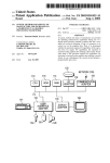
A system, method and article of manufacture are provided
for enhanced handling of graphics data in a frame buffer.
TAMPA, FL 336013239 (Us)
Initially, graphics data is received. Thereafter, operations are
(21)
Appl, No;
09/772,523
(22)
Filed:
Jan. 29, 2001
performed on the graphics data utilizing a predetermined set
of macros in combination With a frame buffer procedure. In
use, the graphics data is Written into a frame buffer for being
displayed on a screen.
200
RECEIVING GRAPHICS DATA
i2
I
204
PERFORMING OPERATIONS ON THE GRAPHICS DATA UTILIZING A /
PREDETERMINED SET OF MACROS IN COMBINATION WITH A
FRAME BUFFER PROCEDURE
I
206
WRITING THE GRAPHICS DATA INTO A FRAME BUFFER FOR BEING
DISPLAYED ON A SCREEN
Patent Application Publication
Dec. 5, 2002 Sheet 1 0f 6
US 2002/0180742 A1
DATA
1O /
SOURCE
13 /
MEMORY
VERTEX
TRANS
14 /
16
/
FORMATION
LIGHTING
CLIP
/ RENDERENG
18
FRAME
1 9 -—-—-"""
BUFFER
i
20
\
DlSPLAY
Figure 1
(PRIOR ART)
12
Patent Application Publication
Dec. 5, 2002 Sheet 2 0f 6
US 2002/0180742 A1
120
110
\
116
\
CPU
ROM
1/0
ADAPTER
T (/)N
COMMUNICA l
ADAPTER
136
138
\
\
USER
INTERFACE
DISPLAY
ADAPTER
1
126
113
RAM
\
132
é NETWORK(135)
‘X 134
114
\
ADAPTER
123
Fig. 1A
Patent Application Publication
Dec. 5, 2002 Sheet 3 0f 6
US 2002/0180742 A1
200
RECEIVING GRAPHICS DATA
PERFORMING OPERATIONS ON THE GRAPHICS DATA UTILIZING A _/
PREDETERMINED SET OF MACROS IN COMBINATION WITH A
FRAME BUFFER PROCEDURE
I
WRITING THE GRAPHICS DATA INTO A FRAME BUFFER FOR BEING _/
DISPLAYED ON A SCREEN
Fig. 2
Patent Application Publication
400
Dec. 5, 2002 Sheet 4 0f 6
Fileriame
Purpose
lcddnvenh
Driver for the LCD display.
framebufh
Runs the frame buffer.
US 2002/0180742 A1
Fig. 3
300
Macro Name
Type
Purpose
pr1nt_shape
proc
Called from gfx_drawRect to set the parameters to initiat
drawing a rectangle
gfx_interpret__Line
proc
Interprets the shape edges when drawing a triangle.
Macro Name
Type
Purpose
gfx_pr1ntShapeProcess
proc
Processes all the shape drawing function calls, and
402
contains the actual shape drawing code. This must be run
in the main par loop.
gfx_drawRect
proc
Sets the parameters to initiate drawing a rectangle.
gfx_drawTriangle
proc
Sets the parameters to initiate drawing a triangle
gfx_drawCircie
proc
Sets the parameters to initiate drawing a circle
gfx_drawLine
proc
Draws a line between two points
gfx_clearScreen
proc
Sets the parameters to clear the screen to a certain colour.
gfx_drawlBitloon
proc
Draws a bitmap to the screen from a 1-bit icon rom.
(Widths of rorn index may need adjusting for different
sized roms).
gfx_draw24Bitlcon
proc
Draws a bitmap to the screen from a 24-bit icon rom.
(Widths of rom index may need adjusting for different
sized roms).
Fig. 4
Patent App 1'lca tion Publication
Dec. 5, 2002 Sheet 5 0 f 6
US 2002/0 180742 A1
500
interpc'ate Pixel
Position
draw horizontal
line between
Pixels
Patent Application Publication
Dec. 5, 2002 Sheet 6 0f 6
US 2002/0180742 A1
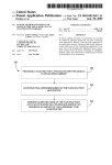
600
Macro
gfx_draWRect
g?:__dravf1‘riang1e
gfX_drawCirc1e
Clock Speed Estimate
(MHZ)
28.9
25.6
15.7
Fig. 6
US 2002/0180742 A1
GRAPHICS MACROS FOR A FRAME BUFFER
FIELD OF THE INVENTION
[0001] The present invention relates to graphics process
ing systems and more particularly to improving frame
buffering in graphics processing systems.
BACKGROUND OF THE INVENTION
[0002] Rendering
and displaying three-dimensional
graphics typically involves many calculations and compu
tations. For example, to render a three dimensional object, a
set of coordinate points or vertices that de?ne the object to
be rendered must be formed. Vertices can be joined to form
polygons that de?ne the surface of the object to be rendered
and displayed. Once the vertices that de?ne an object are
formed, the vertices must be transformed from an object or
model frame of reference to a World frame of reference and
?nally to tWo-dimensional coordinates that can be displayed
on a ?at display device. Along the Way, vertices may be
rotated, scaled, eliminated or clipped because they fall
outside the vieWable area, lit by various lighting schemes,
coloriZed, and so forth. Thus the process of rendering and
displaying a three-dimensional object can be computation
ally intensive and may involve a large number of vertices.
Dec. 5, 2002
address. Planes are grouped together to form multi-bit
values for the attributes of the pixels they represent.
Attributes include the RGB intensities, and in many systems
ON and OFF for pixels in an “overlay” plane that is merged
With data in other planes. For instance, an overlay plane
might contain a cursor, and the presence of a bit in the
overlay plane might force saturation intensity for all three
electron guns, regardless of the actual RGB values for that
pixel. In graphics systems With tWo-dimensional displays
that are intended for use With solid modeling of three
dimensional objects, there is frequently another attribute that
is stored for each pixel: its depth. HardWare storage of depth
values greatly facilitates hidden surface removal, as it alloWs
the hardWare to automatically suppress pixels that are not
upon the outer surface facing the vieWer.
[0006] In accordance With What has been described above,
it is not unusual to ?nd graphics systems With betWeen
tWenty-four and forty planes of frame buffer memory:
perhaps three sets of eight for RGB values and sixteen or
more for Z, or depth, values. Considering that the monitor
could easily be 1280 pixels Wide and 1024 pixels high, and
that refreshing the display at a poWer line frequency of 60
HZ is a requirement, it can be concluded that a neW pixel of
tWenty -four or more bits (and possibly quali?ed for depth)
must be obtained for the monitor from the frame buffer at a
[0003] A general system that implements a graphics pipe
rate of approximately one pixel every nine nanoseconds. To
line system is illustrated in Prior Art FIG. 1. In this system,
some extent the advent of so called “video display RAM’S”
data source 10 generates a stream of expanded vertices
de?ning primitives. These vertices are passed one at a time,
ports that read blocks of data at high speed for use by a
has made this easier to do. They have special high speed
through pipelined graphic system 12 via vertex memory 13
shifter that, When grouped With the shifters of other planes
for storage purposes. Once the expanded vertices are
received from the vertex memory 13 into the pipelined
graphic system 12, the vertices are transformed and lit by a
transformation module 14 and a lighting module 16, respec
for the same color, produce the multi-bit values for color
intensity. These multi-bit values are applied to digital-to
tively, and further clipped and set-up for rendering by a
rasteriZer 18, thus generating rendered primitives that are
stored in a frame buffer 19 and then displayed on display
device 20.
[0004] During operation, the transform module 14 may be
analog converters (DAC’s) that in turn generate the signals
that actually drive the electron guns.
[0007] Despite the video RAM’s, formidable problems
remain concerning the task of getting the data into the frame
buffer in the ?rst place. In the long run, the graphics system
Will not be able to manipulate an image (draW it, rotate it, cut
a hole in it, etc.) any faster than the image can be put into
used to perform scaling, rotation, and projection of a set of
the frame buffer. The speed With Which this can be done is
three dimensional vertices from their local or model coor
dinates to the tWo dimensional WindoW that Will be used to
one important aspect of “high performance” in a graphics
system. Recalling the purpose for caching in a conventional
display the rendered object. The lighting module 16 sets the
computer system, it Will be noted that there is a certain
similarity. It Would be desirable if a Way could be found to
color and appearance of a vertex based on various lighting
Ware or softWare structure that in turn moves the rendered
cache pixels into a high speed memory and reduce the
number of Write operations made into the frame buffer. If
this could be done Without sacri?cing other desirable fea
tures it Would signi?cantly increase the rate With Which data
could be put into the frame buffer. This is indeed desirable,
since much Work has been done to develop and perfect
data to a display device.
dedicated hardWare to generate at high speed pixel values
schemes, light locations, ambient light levels, materials, and
so forth. The rasteriZation module 18 rasteriZes or renders
vertices that have previously been transformed and/or lit.
The rasteriZation module 18 renders the object to a rendering
target Which can be a display device or intermediate hard
[0005] The frame buffer 19 has an address for each pixel
component of the display 20. The frame buffer 19 is also
accessed by another mechanism that reads the contents of
the frame buffer 19 to create the corresponding pixel by
pixel image upon a the display 20. Typically, the display 20
Will be a color CRT With red, green and blue (RGB) electron
guns Whose intensities are varied by discrete steps to pro
duce a Wide range of colors. Accordingly, the frame buffer
19 is divided into portions containing multi-bit values for
each color of every pixel. The preferred Way to do this is to
organiZe the frame buffer 19 into “planes” Which each
receive the same address. Each plane holds one bit at each
from a more abstract description of the image to be rendered.
[0008] Each plane of frame buffer memory is equipped
With a corresponding plane of a pixel cache. The pixel
rendering hardWare stores computed pixel values into the
frame buffer by Way of the cache. Those familiar With pixel
rendering mechanisms Will appreciate that the order in
Which pixels are calculated is not necessarily related to the
order they are accessed for use in driving the monitor, Which
is typically vertically by horiZontal roWs for a raster scanned
CRT. Instead, pixels are apt to be generated in an order that
makes sense in light of the techniques being used to repre
sent the object. A Wire frame model Would rely heavily on
Dec. 5, 2002
US 2002/0180742 Al
the drawing of arbitrarily oriented vectors, While shaded
polygons Would rely heavily upon an area ?ll based on
successive horiZontal lines of pixels. For a curved surface
the successive horiZontal lines are apt to be fairly short, may
be of varying lengths, and might not line up exactly above
or beneath each other. Clearly, the preferred pixel rendering
techniques are no respecters of sequentially addressed
memory spaces. Yet the sequence of generated pixels are
still strongly related by just more than being consecutive
members in some order of pixel generation; their locations
in the ?nal image are physically “close” to each other. That
is, sequentially generated pixels are apt to posses a shared
“locality.” That this is so has been noticed by others, and has
been termed the “principle of locality.” It seems clear that to
maximiZe the number of hits, a cache for a frame buffer
ought to operate in vieW of the principle of locality. But it
is also clear that a different type of locality obtains for area
?ll operations than does for arbitrary vectors.
[0009] A “tile” is a rectangular collection of pixels. Vari
ous schemes for manipulating pixels in groups as tiles have
been proposed. It Would seem that What a pixel cache for a
frame buffer ought to do, at least in part, is cache a tile. But
again, the tile shape best suited for area ?ll operations Would
be one that is one pixel high by some suitably long number
of pixels. The optimum tile shape for the draWing of
arbitrary vectors can be shoWn to be a square. So What is
needed then, is a pixel cache Whose “shape” is adjustable
not the cache, Was loaded With a copy of that region (tile) of
the frame buffer that the cache Was then to represent. Data
Was then Written to the cache until there Was a miss. Then the
frame buffer controller simultaneously copied all of the bits
of each plane in the cache into each SOURCE; this frees the
cache for immediate use in storing neW pixel values. The
frame buffer controller proceeded to combine each
SOURCE With its associated DESTINATION according to
the desired rule (OR, AND, XOR, etc.). The result Was
further modi?ed by the associated PATTERN, Which can be
used to impose special deviations upon the pixel data. For
example, PATTERN might suppress a regular succession of
pixels to create “holes” into Which might later be placed
pixels of another object, thus creating the illusion of trans
parency. HoWever achieved, the result is Written, all sixteen
bits in parallel, for each plane, to the frame buffer. The
mapping of pixel addresses into the cache and the parallel
Write into the frame buffer (i.e., the mapping of the cache
contents back into frame buffer addresses) are automatically
adjusted according to the siZe and shape of the tile being
handled. Thus, one aspect of the invention to be disclosed is
a pixel cache memory that accepts programmatically vari
able tile siZes. It Will be further understood as the description
proceeds that the tiles may be aligned on selected pixel
boundaries, and that those boundaries need not be perma
nently ?xed in advance.
[0012] Up to noW, prior art frame buffer procedures such
according to the type of tile best suited for use With the type
as the foregoing example execute command after command
of pixel rendering to be undertaken.
Without the use of macros of any sort.
[0010] That object can be achieved by a pixel cache, frame
buffer controller and frame buffer memory organiZation that
SUMMARY OF THE INVENTION
cooperate to implement a cache corresponding to a tile of
a number of separately addressable groups. Each group is
[0013] A system, method and article of manufacture are
provided for enhanced handling of graphics data in a frame
buffer. Initially, graphics data is received. Thereafter, opera
tions are performed on the graphics data utiliZing a prede
composed of one or more bits. Along the scan lines of the
raster groups repeat in a regular order. Successive scan lines
procedure. In use, the graphics data is Written into a frame
adjustable rectangular dimensions. The frame buffer
memory organiZation involves dividing the frame buffer into
termined set of macros in combination With a frame buffer
have different starting groups in the pattern of repetition.
Thus, Whether a tile proceeds horiZontally along a scan line,
buffer for being displayed on a screen.
or vertically across successive scan lines, different groups
[0014]
are accessed for the pixels in that tile. This alloWs the entire
tile to be fetched With one memory cycle. In such a scheme
macros may include a function identi?er and parameters
In one embodiment of the present invention, the
adjacent pixel ad dresses do not necessarily map into adja
associated thereWith. Further, the operations may include a
Wait operation. Moreover, the operations may include a draW
cent frame buffer addresses, as in conventional bit-mapped
rectangle operation, draW circle operation, and/or draW
displays. Instead, an address manipulator Within the frame
buffer controller converts a pixel address (screen location)
into a collection of addresses (one for each group) according
to rules determined by the shape of the tile to be accessed.
[0011] Each plane of the frame buffer memory includes a
sixteen-bit plane of an RGB pixel cache and a sixteen-bit
plane of a Z value cache. (It Will be understood, of course,
that the number sixteen is merely exemplary, and is not the
only practical siZe of pixel cache.) For each bit in a pixel’s
RGB values, the pixel’s (X, Y) location on the monitor is
mapped into the proper location of the plane of the RGB
cache associated With that bit. If there is a hit, then the pixel
is Written to the cache. If there is a miss, then the cache is
Written out to the frame buffer in accordance With a replace
ment rule similar to those used With so-called “line movers”
or “bitblts.” The replacement rule uses sixteen-bit registers
named SOURCE, DESTINATION and PATTERN. There is
one of these registers for each plane of frame buffer memory.
At the time of the preceding miss, each DESTINATION, and
triangle operation.
BRIEF DESCRIPTION OF THE DRAWINGS
[0015]
The invention Will be better understood When con
sideration is given to the folloWing detailed description
thereof. Such description makes reference to the annexed
draWings Wherein:
[0016]
FIG. 1 illustrates a prior art graphics pipeline;
[0017] FIG. 1A is a schematic diagram of a hardWare
implementation of one embodiment of the present invention;
[0018] FIG. 2 illustrates a method for enhanced handling
of graphics data in a frame buffer;
[0019]
FIG. 3 illustrates the various external ?les may be
may be needed by the present invention;
[0020]
FIG. 4 illustrates internal and external macros
associated With the present invention;
Dec. 5, 2002
US 2002/0180742 A1
[0021] FIG. 5 illustrates the DraW Triangle Macro, in
and reProgrammable ROM or EEPROM is an example of
accordance With one embodiment of the present invention;
and
nonvolatile reprogrammable memory. The con?guration
[0022]
FIG. 6 illustrates a chart shoWing speeds With
Which the various macros may operate.
DETAILED DESCRIPTION OF THE
PREFERRED EMBODIMENTS
[0023] Apreferred embodiment of a system in accordance
With the present invention is preferably practiced in the
context of a personal computer such as an IBM compatible
personal computer, Apple Macintosh computer or UNIX
based Workstation. A representative hardWare environment
is depicted in FIG. 1A, Which illustrates a typical hardWare
de?ning memory of an FPGA device can be formed of
mixture of different kinds of memory elements if desired
(e.g., SRAM and EEPROM) although this is not a popular
approach.
[0027] (2) Input/Output Blocks (IOB’s) are provided for
interconnecting other internal circuit components of the
FPGA device With external circuitry. The IOB’s’ may have
?xed con?gurations or they may be con?gurable in accor
dance With user-provided con?guration instructions stored
in the con?guration-de?ning memory means.
[0028] (3) Con?gurable Logic Blocks (CLB’s) are pro
vided for carrying out user-programmed logic functions as
con?guration of a Works tation in accordance With a pre
de?ned by user-provided con?guration instructions stored in
ferred embodiment having a central processing unit 110,
the con?guration-de?ning memory means.
such as a microprocessor, and a number of other units
interconnected via a system bus 112. The Workstation shoWn
in FIG. 1A includes a Random Access Memory (RAM) 114,
Read Only Memory (ROM) 116, an I/O adapter 118 for
connecting peripheral devices such as disk storage units 120
to the bus 112, a user interface adapter 122 for connecting
[0029] Typically, each of the many CLB’s of an FPGA has
at least one lookup table (LUT) that is user-con?gurable to
de?ne any desired truth table,—to the extent alloWed by the
address space of the LUT. Each CLB may have other
resources such as LUT input signal pre-processing resources
132, and/or other user interface devices such as a touch
and LUT output signal post-processing resources. Although
the term ‘CLB’ Was adopted by early pioneers of FPGA
screen (not shoWn) to the bus 112, communication adapter
technology, it is not uncommon to see other names being
134 for connecting the Workstation to a communication
given to the repeated portion of the FPGA that carries out
user-programmed logic functions. The term, ‘LAB’ is used
a keyboard 124, a mouse 126, a speaker 128, a microphone
netWork (e.g., a data processing netWork) and a display
adapter 136 for connecting the bus 112 to a display device
138. The Workstation typically has resident thereon an
operating system such as the Microsoft WindoWs NT or
Windows/95 Operating System (OS), the IBM OS/2 oper
ating system, the MAC OS, or UNIX operating system.
Those skilled in the art Will appreciate that the present
invention may also be implemented on platforms and oper
ating systems other than those mentioned.
for example in US. Pat. No. 5,260,611 to refer to a repeated
unit having a 4-input LUT.
[0030] (4) An interconnect netWork is provided for carry
ing signal traffic Within the FPGA device betWeen various
CLB’s and/or betWeen various IOB’s and/or betWeen vari
ous IOB’s and CLB’s. At least part of the interconnect
netWork is typically con?gurable so as to alloW for pro
grammably-de?ned routing of signals betWeen various
[0024] The hardWare environment set forth in FIG. 1A
includes a graphic acceleration integrated circuit Which
CLB’s and/or IOB’s in accordance With user-de?ned routing
instructions stored in the con?guration-de?ning memory
of?oads graphics processing from the central processing unit
means.
110. In one embodiment of the present invention, the graph
ics acceleration integrated circuit may include, at least in
part, a ?eld programmable gate array (FPGA) device. Use of
[0031] In some instances, FPGA devices may additionally
include embedded volatile memory for serving as scratchpad
such device provides ?exibility in functionality, While main
memory for the CLB’s or as FIFO or LIFO circuitry. The
taining high processing speeds.
embedded volatile memory may be fairly siZable and can
have 1 million or more storage bits in addition to the storage
[0025]
bits of the device’s con?guration memory.
Examples of such FPGA devices include the
XC2000TM and XC3000TM families of FPGA devices intro
duced by Xilinx, Inc. of San Jose, Calif. The architectures of
these devices are exempli?ed in US. Pat. Nos. 4,642,487;
[0032] Modern FPGA’s tend to be fairly complex. They
typically offer a large spectrum of user-con?gurable options
4,706,216; 4,713,557; and 4,758,985; each of Which is
originally assigned to Xilinx, Inc. and Which are herein
incorporated by reference for all purposes. It should be
noted, hoWever, that FPGA’s of any type may be employed
With respect to hoW each of many CLB’s should be con?g
ured, hoW each of many interconnect resources should be
con?gured, and/or hoW each of many IOB’s should be
in the context of the prese nt invention. An FPGA device can
millions of con?gurable bits that may need to be individu
ally set or cleared during con?guration of each FPGA
device.
be characteriZed as an integrated circuit that has four major
features as folloWs.
con?gured. This means that there can be thousands or
[0026] (1) A user-accessible, con?guration-de?ning
[0033] Rather than determining With pencil and paper hoW
memory means, such as SRAM, PROM, EPROM,
each of the con?gurable resources of an FPGA device
EEPROM, anti-fused, fused, or other, is provided in the
should be programmed, it is common practice to employ a
FPGA device so as to be at least once-programmable by
computer and appropriate FPGA-con?guring softWare to
device users for de?ning user-provided con?guration
automatically generate the con?guration instruction signals
instructions. Static Random Access Memory or SRAM is of
course, a form of reprogrammable memory that can be
that Will be supplied to, and that Will ultimately cause an
unprogrammed FPGA to implement a speci?c design. (The
differently programmed many times. Electrically Erasable
con?guration instruction signals may also de?ne an initial
Dec. 5, 2002
US 2002/0180742 A1
state for the implemented design, that is, initial set and reset
[0041]
states for embedded ?ip ?ops and/or embedded scratchpad
needed to restore the lost data When poWer is shut off and
then re-applied to the FPGA or When another like event calls
memory cells.)
Some form of con?guration restoration means is
for con?guration restoration (e.g., corruption of state data
[0034] The number of logic bits that are used for de?ning
the con?guration instructions of a given FPGA device tends
Within scratchpad memory).
to be fairly large (e.g., 1 Megabits or more) and usually
[0042] The con?guration restoration means can take many
forms. If the FPGA device resides in a relatively large
system that has a magnetic or optical or opto-magnetic form
groWs With the siZe and complexity of the target FPGA.
Time spent in loading con?guration instructions and veri
out in the ?eld.
of nonvolatile memory (e.g., a hard magnetic disk)—and the
latency of poWering up such a optical/magnetic device
and/or of loading con?guration instructions from such an
[0035]
optical/magnetic form of nonvolatile memory can be toler
ated—then the optical/magnetic memory device can be used
fying that the instructions have been correctly loaded can
become signi?cant, particularly When such loading is carried
For many reasons, it is often desirable to have
in-system reprogramming capabilities so that recon?gura
tion of FPGA’s can be carried out in the ?eld.
[0036] FPGA devices that have con?guration memories of
the reprogrammable kind are, at least in theory, ‘in-system
programmable’ (ISP). This means no more than that a
as a nonvolatile con?guration restoration means that redun
dantly stores the con?guration data and is used to reload the
same into the system’s FPGA device(s) during poWer-up
operations (and/or other restoration cycles).
possibility exists for changing the con?guration instructions
[0043] On the other hand, if the FPGA device(s) resides in
a relatively small system that does not have such optical/
Within the FPGA device While the FPGA device is ‘in
magnetic devices, and/or if the latency of loading con?gu
system’ because the con?guration memory is inherently
reprogrammable. The term, ‘in-system’ as used herein indi
ration memory data from such an optical/magnetic device is
not tolerable, then a smaller and/or faster con?guration
cates that the FPGA device remains connected to an appli
restoration means may be called for.
cation-speci?c printed circuit board or to another form of
end-use system during reprogramming. The end-use system
[0044] Many end-use systems such as cable-TV set tops,
satellite receiver boxes, and communications sWitching
is of course, one Which contains the FPGA device and for
Which the FPGA device is to-be at least once con?gured to
boxes are constrained by prespeci?ed design limitations on
operate Within in accordance With prede?ned, end-use or ‘in
physical siZe and/or poWer-up timing and/or security provi
the ?eld’ application speci?cations.
sions and/or other provisions such that they cannot rely on
[0037] The possibility of recon?guring such inherently
magnetic or optical technologies (or on network/satellite
doWnloads) for performing con?guration restoration. Their
reprogrammable FPGA’s does not mean that con?guration
changes can alWays be made With any end-use system. Nor
does it mean that, Where in-system reprogramming is pos
sible, that recon?guration of the FPGA can be made in
timely fashion or convenient fashion from the perspective of
the end-use system or its users. (Users of the end-use system
Within the end-use system; (2) being able to store FPGA
can be located either locally or remotely relative to the
con?guration data during prolonged poWer outage periods;
end-use system.)
[0038] Although there may be many instances in Which it
is desirable to alter a pre-existing con?guration of an ‘in the
?eld’ FPGA (With the alteration commands coming either
from a remote site or from the local site of the FPGA), there
are certain practical considerations that may make such
in-system reprogrammability of FPGA’s more dif?cult than
designs instead call for a relatively small and fast acting,
non-volatile memory device (such as a securely-packaged
EPROM IC), for performing the con?guration restoration
function. The small/fast device is expected to satisfy appli
cation-speci?c criteria such as: (1) being securely retained
and (3) being able to quickly and automatically re-load the
con?guration instructions back into the volatile con?gura
tion memory (SRAM) of the FPGA device each time poWer
is turned back on or another event calls for con?guration
restoration.
[0045] The term ‘CROP device’ Will be used herein to
refer in a general Way to this form of compact, nonvolatile,
?rst apparent (that is, When conventional techniques for
and fast-acting device that performs ‘Con?guration-Restor
FPGA recon?guration are folloWed).
ing On PoWer-up’ services for an associated FPGA device.
[0039] A popular class of FPGA integrated circuits (IC’s)
[0046] Unlike its supported, volatilely reprogrammable
relies on volatile memory technologies such as SRAM
FPGA device, the corresponding CROP device is not vola
(static random access memory) for implementing on-chip
tile, and it is generally not ‘in-system programmable’.
con?guration memory cells. The popularity of such volatile
memory technologies is oWed primarily to the inherent
Instead, the CROP device is generally of a completely
reprogrammability of the memory over a device lifetime that
can include an essentially unlimited number of reprogram
ming cycles.
[0040] There is a price to be paid for these advantageous
features, hoWever. The price is the inherent volatility of the
con?guration data as stored in the FPGA device. Each time
poWer to the FPGA device is shut off, the volatile con?gu
ration memory cells lose their con?guration data. Other
events may also cause corruption or loss of data from
volatile memory cells Within the FPGA device.
nonprogrammable type such as exempli?ed by mask-pro
grammed ROM IC’s or by once-only programmable, fuse
based PROM IC’s. Examples of such CROP devices include
a product family that the Xilinx company provides under the
designation ‘Serial Con?guration PROMs’ and under the
trade name, XC1700D.TM. These serial CROP devices
employ one-time programmable PROM (Programmable
Read Only Memory) cells for storing con?guration instruc
tions in nonvolatile fashion.
[0047] Apreferred embodiment is Written using Handel-C.
Handel-C is a programming language marketed by Celoxica
Dec. 5, 2002
US 2002/0180742 A1
Limited. Handel-C is a programming language that enables
a software or hardWare engineer to target directly FPGAs
(Field Programmable Gate Arrays) in a similar fashion to
classical microprocessor cross-compiler development tools,
data to perform its speci?c task. OOP, therefore, vieWs a
computer program as a collection of largely autonomous
components, called objects, each of Which is responsible for
a speci?c task. This concept of packaging data, structures,
Without recourse to a HardWare Description Language.
and procedures together in one component or module is
Thereby alloWing the designer to directly realiZe the raW
real-time computing capability of the FPGA.
called encapsulation.
[0055]
[0048] Handel-C is designed to enable the compilation of
modules Which present an interface that conforms to an
programs into synchronous hardWare; it is aimed at com
object model and Which are accessed at run-time through a
piling high level algorithms directly into gate level hard
component integration architecture. A component integra
Ware.
[0049] The Handel-C syntax is based on that of conven
tional C so programmers familiar With conventional C Will
recogniZe almost all the constructs in the Handel-C lan
guage.
[0050] Sequential programs can be Written in Handel-C
just as in conventional C but to gain the most bene?t in
performance from the target hardWare its inherent parallel
In general, OOP components are reusable softWare
tion architecture is a set of architecture mechanisms Which
alloW softWare modules in different process spaces to utiliZe
each other’s capabilities or functions. This is generally done
by assuming a common component object model on Which
to build the architecture. It is WorthWhile to differentiate
betWeen an object and a class of objects at this point. An
object is a single instance of the class of objects, Which is
often just called a class. A class of objects can be vieWed as
a blueprint, from Which many objects can be formed.
ism must be exploited.
[0056]
[0051] Handel-C includes parallel constructs that provide
that is a part of another object. For example, the object
representing a piston engine is said to have a composition
the means for the programmer to exploit this bene?t in his
applications. The compiler compiles and optimiZes Han
OOP alloWs the programmer to create an object
relationship With the object representing a piston. In reality,
del-C source code into a ?le suitable for simulation or a net
a piston engine comprises a piston, valves and many other
list Which can be placed and routed on a real FPGA.
components; the fact that a piston is an element of a piston
[0052] More information regarding the Handel-C pro
gramming language may be found in “EMBEDDED SOLU
TIONS Handel-C Language Reference Manual: Version
3,”“EMBEDDED SOLUTIONS Handel-C User Manual:
by tWo objects.
Version 3.0,”“EMBEDDED SOLUTIONS Handel-C Inter
facing to other language code blocks: Version 3.0,” and
“EMBEDDED SOLUTIONS Handel-C Preprocessor Ref
erence Manual: Version 2.1,” each authored by Rachel GanZ,
and published by Embedded Solutions Limited, and Which
are each incorporated herein by reference in their entirety.
Additional information may be found in a co-pending appli
cation entitled “SYSTEM, METHOD AND ARTICLE OF
MANUFACTURE FOR INTERFACE CONSTRUCTS IN
A PROGRAMMING LANGUAGE CAPABLE OF PRO
GRAMMING HARDWARE ARCHITECTURES” Which
Was ?led under attorney docket number EMB1P041, and
Which is incorporated herein by reference in its entirety.
[0053] Another embodiment of the present invention may
be Written at least in part using JAVA, C, and the C++
language and utiliZe object oriented programming method
ology. Object oriented programming (OOP) has become
increasingly used to develop complex applications. As OOP
moves toWard the mainstream of softWare design and devel
opment, various softWare solutions require adaptation to
engine can be logically and semantically represented in OOP
[0057] OOP also alloWs creation of an object that
“depends from” another object. If there are tWo objects, one
representing a piston engine and the other representing a
piston engine Wherein the piston is made of ceramic, then
the relationship betWeen the tWo objects is not that of
composition. A ceramic piston engine does not make up a
piston engine. Rather it is merely one kind of piston engine
that has one more limitation than the piston engine; its piston
is made of ceramic. In this case, the object representing the
ceramic piston engine is called a derived object, and it
inherits all of the aspects of the object representing the
piston engine and adds further limitation or detail to it. The
object representing the ceramic piston engine “depends
from” the object representing the piston engine. The rela
tionship betWeen these objects is called inheritance.
[0058] When the object or class representing the ceramic
piston engine inherits all of the aspects of the objects
representing the piston engine, it inherits the thermal char
acteristics of a standard piston de?ned in the piston engine
class. HoWever, the ceramic piston engine object overrides
these ceramic speci?c thermal characteristics, Which are
typically different from those associated With a metal piston.
It skips over the original and uses neW functions related to
make use of the bene?ts of OOP. A need exists for these
ceramic pistons. Different kinds of piston engines have
principles of OOP to be applied to a messaging interface of
different characteristics, but may have the same underlying
functions associated With it (e.g., hoW many pistons in the
an electronic messaging system such that a set of OOP
classes and objects for the messaging interface can be
provided.
engine, ignition sequences, lubrication, etc.). To access each
of these functions in any piston engine object, a programmer
[0054]
Would call the same functions With the same names, but each
OOP is a process of developing computer softWare
using objects, including the steps of analyZing the problem,
designing the system, and constructing the program. An
object is a softWare package that contains both data and a
collection of related structures and procedures. Since it
contains both data and a collection of structures and proce
type of piston engine may have different/overriding imple
mentations of functions behind the same name. This ability
to hide different implementations of a function behind the
same name is called polymorphism and it greatly simpli?es
dures, it can be visualiZed as a self-suf?cient component that
communication among objects.
[0059] With the concepts of composition-relationship,
does not require other additional structures, procedures or
encapsulation, inheritance and polymorphism, an object can
Dec. 5, 2002
US 2002/0180742 A1
represent just about anything in the real World. In fact, one’s
logical perception of the reality is the only limit on deter
mining the kinds of things that can become objects in
object-oriented softWare. Some typical categories are as
folloWs:
The bene?ts of object classes can be summariZed,
as folloWs:
[0069] Objects and their corresponding classes break
doWn complex programming problems into many
smaller, simpler problems.
[0060]
Objects can represent physical objects, such as
automobiles in a traf?c-?oW simulation, electrical com
ponents in a circuit-design program, countries in an
economics model, or aircraft in an air-traf?c-control
system.
[0061]
Objects can represent elements of the computer
user environment such as WindoWs, menus or graphics
objects.
[0062] An object can represent an inventory, such as a
personnel ?le or a table of the latitudes and longitudes
of cities.
[0063] An object can represent user-de?ned data types
such as time, angles, and complex numbers, or points
on the plane.
[0064]
[0068]
With this enormous capability of an object to
represent just about any logically separable matters, OOP
alloWs the softWare developer to design and implement a
[0070] Encapsulation enforces data abstraction through
the organiZation of data into small, independent objects
that can communicate With each other. Encapsulation
protects the data in an object from accidental damage,
but alloWs other objects to interact With that data by
calling the object’s member functions and structures.
[0071] Subclassing and inheritance make it possible to
extend and modify objects through deriving neW kinds
of objects from the standard classes available in the
system. Thus, neW capabilities are created Without
having to start from scratch.
[0072] Polymorphism and multiple inheritance make it
possible for different programmers to mix and match
characteristics of many different classes and create
specialiZed objects that can still Work With related
objects in predictable Ways.
[0073] Class hierarchies and containment hierarchies
provide a ?exible mechanism for modeling real-World
objects and the relationships among them.
computer program that is a model of some aspects of reality,
Whether that reality is a physical entity, a process, a system,
or a composition of matter. Since the object can represent
[0074] Libraries of reusable classes are useful in many
situations, but they also have some limitations. For
anything, the software developer can create an object Which
[0075] Complexity. In a complex system, the class
example:
can be used as a component in a larger softWare project in
hierarchies for related classes can become extremely
the future.
confusing, With many doZens or even hundreds of
[0065]
If 90% of a neW OOP softWare program consists of
proven, existing components made from preexisting reus
able objects, then only the remaining 10% of the neW
softWare project has to be Written and tested from scratch.
Since 90% already came from an inventory of extensively
tested reusable objects, the potential domain from Which an
error could originate is 10% of the program. As a result,
OOP enables softWare developers to build objects out of
other, previously built objects.
[0066] This process closely resembles complex machinery
being built out of assemblies and sub-assemblies. OOP
technology, therefore, makes softWare engineering more like
hardWare engineering in that softWare is built from existing
components, Which are available to the developer as objects.
All this adds up to an improved quality of the softWare as
Well as an increased speed of its development.
classes.
[0076] How of control. A program Written With the aid
of class libraries is still responsible for the How of
control (i.e., it must control the interactions among all
the objects created from a particular library). The
programmer has to decide Which functions to call at
What times for Which kinds of objects.
[0077] Duplication of effort. Although class libraries
alloW programmers to use and reuse many small pieces
of code, each programmer puts those pieces together in
a different Way. TWo different programmers can use the
same set of class libraries to Write tWo programs that do
exactly the same thing but Whose internal structure
(i.e., design) may be quite different, depending on
hundreds of small decisions each programmer makes
along the Way. Inevitably, similar pieces of code end up
doing similar things in slightly different Ways and do
not Work as Well together as they should.
[0067] Programming languages are beginning to fully
[0078]
support the OOP principles, such as encapsulation, inherit
ance, polymorphism, and composition-relationship. With
the advent of the C++ language, many commercial softWare
developers have embraced OOP. C++ is an OOP language
that offers a fast, machine -executable code. Furthermore,
C++ is suitable for both commercial-application and sys
tems-programming projects. For noW, C++ appears to be the
most popular choice among many OOP programmers, but
more complex, more programmers are forced to reinvent
there is a host of other OOP languages, such as Smalltalk,
Class libraries are very ?exible. As programs groW
basic solutions to basic problems over and over again. A
relatively neW extension of the class library concept is to
have a frameWork of class libraries. This frameWork is more
complex and consists of signi?cant collections of collabo
rating classes that capture both the small scale patterns and
major mechanisms that implement the common require
ments and design in a speci?c application domain. They
Were ?rst developed to free application programmers from
Common Lisp Object System (CLOS), and Eiffel. Addition
the chores involved in displaying menus, WindoWs, dialog
ally, OOP capabilities are being added to more traditional
boxes, and other standard user interface elements for per
popular computer programming languages such as Pascal.
sonal computers.
Dec. 5, 2002
US 2002/0180742 A1
programmers think about the interaction betWeen the code
design solution for a given problem domain. It typically
includes objects that provide default behavior (e.g., for
they Write and code Written by others. In the early days of
procedural programming, the programmer called libraries
menus and WindoWs), and programmers use it by inheriting
some of that default behavior and overriding other behavior
[0079]
Frameworks also represent a change in the Way
provided by the operating system to perform certain tasks,
so that the frameWork calls application code at the appro
but basically the program executed doWn the page from start
to ?nish, and the programmer Was solely responsible for the
How of control. This Was appropriate for printing out pay
checks, calculating a mathematical table, or solving other
problems With a program that executed in just one Way.
priate times.
[0080] The development of graphical user interfaces
began to turn this procedural programming arrangement
inside out. These interfaces alloW the user, rather than
program logic, to drive the program and decide When certain
actions should be performed. Today, most personal com
puter softWare accomplishes this by means of an event loop
Which monitors the mouse, keyboard, and other sources of
external events and calls the appropriate parts of the pro
grammer’s code acc ording to actions that the user performs.
The programmer no longer determines the order in Which
events occur. Instead, a program is divided into separate
pieces that are called at unpredictable times and in an
unpredictable order. By relinquishing cont rol in this Way to
users, the developer creates a program that is much easier to
use. Nevertheless, individual pieces of the program Written
by the developer still call libraries provided by the operating
system to accomplish certain tasks, and the programmer
must still determine the How of control Within each piece
after it’s called by the event loop. Application code still “sits
on top of” the system.
[0081]
[0085] There are three main differences betWeen frame
Works and class libraries:
[0086] Behavior versus protocol. Class libraries are es
sentially collections of behaviors that you can call
When you Want those individual behaviors in your
program. A frameWork, on the other hand, provides not
only behavior but also the protocol or set of rules that
govern the Ways in Which behaviors can be combined,
including rules for What a programmer is supposed to
provide versus What the frameWork provides.
[0087] Call versus override. With a class library, the
code the programmer instantiates objects and calls their
member functions. It’s possible to instantiate and call
objects in the same Way With a frameWork (i.e., to treat
the frameWork as a class library), but to take full
advantage of a frameWork’s reusable design, a pro
grammer typically Writes code that overrides and is
called by the frameWork. The frameWork manages the
How of control among its objects. Writing a program
involves dividing responsibilities among the various
pieces of softWare that are called by the frameWork
rather than specifying hoW the different pieces should
Work together.
Even event loop programs require programmers to
Write a lot of code that should not need to be Written
separately for every application. The concept of an applica
tion frameWork carries the event loop concept further.
Instead of dealing With all the nuts and bolts of constructing
basic menus, WindoWs, and dialog boxes and then making
these things all Work together, programmers using applica
tion frameWorks start With Working application code and
basic user interface elements in place. Subsequently, they
build from there by replacing some of the generic capabili
ties of the frameWork With the speci?c capabilities of the
intended application.
[0082] Application frameWorks reduce the total amount of
[0088] Implementation versus design. With class librar
ies, programmers reuse only implementations, Whereas
With frameWorks, they reuse design. A frameWork
embodies the Way a family of related programs or
pieces of softWare Work. It represents a generic design
solution that can be adapted to a variety of speci?c
problems in a given domain. For example, a single
frameWork can embody the Way a user interface Works,
even though tWo different user interfaces created With
the same frameWork might solve quite different inter
face problems.
code that a programmer has to Write from scratch. HoWever,
[0089] Thus, through the development of frameWorks for
solutions to various problems and programming tasks, sig
because the frameWork is really a generic application that
displays WindoWs, supports copy and paste, and so on, the
softWare can be achieved. A preferred embodiment of the
programmer can also relinquish control to a greater degree
invention utiliZes HyperText Markup Language (HTML) to
than event loop programs permit. The frameWork code takes
care of almost all event handling and How of control, and the
programmer’s code is called only When the frameWork
needs it (e.g., to create or manipulate a proprietary data
implement documents on the Internet together With a gen
eral-purpose secure communication protocol for a transport
structure).
[0083] A programmer Writing a frameWork program not
only relinquishes control to the user (as is also true for event
loop programs), but also relinquishes the detailed How of
control Within the program to the frameWork. This approach
alloWs the creation of more complex systems that Work
together in interesting Ways, as opposed to isolated pro
grams, having custom code, being created over and over
again for similar problems.
[0084] Thus, as is explained above, a frameWork basically
is a collection of cooperating classes that make up a reusable
ni?cant reductions in the design and development effort for
medium betWeen the client and the NeWco. HTTP or other
protocols could be readily substituted for HTML Without
undue experimentation. Information on these products is
available in T. Bemers-Lee, D. Connoly, “RFC 1866: Hyper
text Markup Language-2.0” (Nov. 1995); and R. Fielding, H,
Frystyk, T. Berners-Lee, J. Gettys and J. C. Mogul, “Hyper
text Transfer Protocol—HTTP/1.1: HTTP Working Group
Internet Draft” (May 2, 1996). HTML is a simple data
format used to create hypertext documents that are portable
from one platform to another. HTML documents are SGML
documents With generic semantics that are appropriate for
representing information from a Wide range of domains.
HTML has been in use by the World-Wide Web global
information initiative since 1990. HTML is an application of
Dec. 5, 2002
US 2002/0180742 A1
ISO Standard 8879; 1986 Information Processing Text and
Of?ce Systems; Standard Generalized Markup Language
(SGML).
[0090] To date, Web development tools have been limited
in their ability to create dynamic Web applications Which
span from client to server and interoperate With existing
computing resources. Until recently, HTML has been the
dominant technology used in development of Web-based
solutions. HoWever, HTML has proven to be inadequate in
the folloWing areas:
[0091] Poor performance;
[0092] Restricted user interface capabilities;
[0093] Can only produce static Web pages;
[0094] Lack of interoperability With existing applica
tions and data; and
[0095]
Inability to scale.
[0096] Sun Microsystem’s Java language solves many of
the client-side problems by:
[0097] Improving performance on the client side;
[0098] Enabling the creation of dynamic, real-time Web
applications; and
[0099]
Providing the ability to create a Wide variety of
user interface components.
[0100]
With Java, developers can create robust User Inter
face (UI) components. Custom “Widgets” (e.g., real-time
stock tickers, animated icons, etc.) can be created, and
client-side performance is improved. Unlike HTML, Java
supports the notion of client-side validation, offloading
appropriate processing onto the client for improved perfor
building blocks are called ActiveX Controls, small, fast
components that enable developers to embed parts of soft
Ware in hypertext markup language (HTML) pages. ActiveX
Controls Work With a variety of programming languages
including Microsoft Visual C++, Borland Delphi, Microsoft
Visual Basic programming system and, in the future,
Microsoft’s development tool for Java, code named
“Jakarta.” ActiveX Technologies also includes ActiveX
Server FrameWork, alloWing developers to create server
applications. One of ordinary skill in the art readily recog
niZes that ActiveX could be substituted for JAVA Without
undue experimentation to practice the invention.
[0103]
In the one embodiment of the present invention, the
aforementioned Handel-C programming language is capable
of executing macros for Working in conjunction With a frame
buffer procedure for draWing graphics to the screen. FIG. 2
illustrates a method 200 for enhanced handling of graphics
data in a frame buffer. Initially, in operation 202, graphics
data is received. Thereafter, in operation 204, operations are
performed on the graphics data utiliZing a predetermined set
of macros in combination With a frame buffer procedure.
The graphics data is Written into a frame buffer for being
displayed on a screen. Note operation 206.
[0104] The Handel-C compiler passes source code
through a standard C-programming language preprocessor
before compilation alloWing the use of “#de?ne” to de?ne
constants and macros in the usual manner. There are some
limitations to this approach. Since the preprocessor can only
perform textual substitution, some useful macro constructs
cannot be expressed. For example, there is no Way to create
mance. Dynamic, real-time Web pages can be created. Using
the above-mentioned custom UI components, dynamic Web
recursive macros using the preprocessor. Handel-C provides
pages can also be created.
be de?ned (for example, recursive macro expressions). In
[0101]
Sun’s Java language has emerged as an industry
additional macro support to alloW more poWerful macros to
addition, Handel-C supports shared macros to generate one
recogniZed language for “programming the Internet.” Sun
de?nes Java as: “a simple, obj ect-oriented, distributed, inter
piece of hardWare Which is shared by a number of parts of
the overall program similar to the Way that procedures alloW
preted, robust, secure, architecture-neutral, portable, high
conventional C to share one piece of code betWeen many
parts of a conventional program.
performance, multithreaded, dynamic, buZZWord-compliant,
general-purpose programming language. Java supports pro
gramming for the Internet in the form of platform-indepen
dent Java applets.” Java applets are small, specialiZed appli
cations that comply With Sun’s Java Application
Programming Interface (API) alloWing developers to add
“interactive content” to Web documents (e.g., simple ani
mations, page adornments, basic games, etc.). Applets
execute Within a J ava-compatible s broWser (e.g., Netscape
Navigator) by copying code from the server to client. From
a language standpoint, Java’s core feature set is based on
C++. Sun’s Java literature states that Java is basically, “C++
With extensions from Objective C for more dynamic method
resolution.”
[0102] Another technology that provides similar function
to JAVA is provided by Microsoft and ActiveX Technolo
gies, to give developers and Web designers WhereWithal to
build dynamic content for the Internet and personal com
puters. ActiveX includes tools for developing animation,
3-D virtual reality, video and other multimedia content. The
tools use Internet standards, Work on multiple platforms, and
are being supported by over 100 companies. The group’s
[0105] By this design, the present invention has the fol
loWing features:
[0106] Compliments frame buffering.
[0107]
Graphics macros for circles, squares, and tri
angles.
[0108]
Line draWing macro.
[0109]
Icon draWing macros for 24-bit and mono
chrome bitmaps.
[0110] FIG. 3 illustrates the various external ?les 300 may
be may be needed by the present invention. Note Appendix
A. FIG. 4 illustrates internal and external macros, 400 and
402, associated With the present invention. Such macros are
de?ned in the ?le “Gfx.h.” Which is Well knoWn in the
Handel-C programming language. Such macros are split into
tWo sections: internal macros Which are speci?c to Gfx.h.
External macros should be called by a main program.
Dec. 5, 2002
US 2002/0180742 A1
[0111]
One macro, gfx_printShapeProcess, is run as one of
[0124] With the exceptions of icon draWing and line
the main parallel processes of a graphics application. It
draWing processes, the macro gfx_printShapeProcess con
consists of four main sections:
tains all the shape draWing code for the shape macros. This
may be called from the main par loop. The shape draWing
macros simply set various parameters to initiate the required
[0112] Wait Stage
[0113] When no shape drawing calls are made, print
_shape_run, the shape draWing ?ag, is set to off and the
function and these must be called every time a shape is to be
process Waits for initiation.
draWn. FIG. 6 illustrates a chart 600 shoWing speeds With
[0114] DraW Rectangle
Which the various macros may operate.
[0115]
The present macro is run in parallel With the circle
APPENDIX A
and triangle draWing stages. Pixels are draWn directly into
the frame buffer at the relevant place, in roWs. When each
roW is completed, the y variable is incremented and the X
/*96*96*96*96*9696*96*96*96*******************************************
variable is reset to its original position for the start of the
next roW. If one of the other shape stages is running, a delay
#include “syncgenh”
is performed.
[0116] DraW Circle
[0117]
* File
:
lcddriver.h
unsigned 1O sx, sy;
//adjust a 15 bit colour to an 18 bit colour
macro expr videoiadjust(pixel) =
The present macro is run in parallel With the
*
( (unsigned 6) (pixel[14:10]@O)) @
( (unsigned 6) (pixel[9:5] @O)) @
( (unsigned 6) (pixel[4:0] @O));
macro expr bufferiadjust(pixel) = O@(pixel[17:13])@(pixel[11:7])
rectangle and triangle draWing stages. The program steps
@(pixel[5:1]);
through a square of Width tWice the radius, centered at the
same point as the circle. Each pixel is tested for satisfaction
macro expr RGB(r, g, b) = ((unsigned 6)r)@((unsigned 6)g)@((unsigned
of Pythagoras’ Theorem. If the inequality of Table 1 is
satis?ed, the pixel (px, py) is inside the circle and the color
macro
macro
macro
macro
macro
macro
is Written to the frame buffer.
TABLE 1
6)b);
expr
expr
expr
expr
expr
expr
black = RGB(0,0,0);
White = RGB(63,63,63);
red = RGB(63,0,0);
blue = RGB(0,0,63);
green = RGB(O,63,0);
grey = RGB(17,17,17);
macro expr purple = RGB(O, 63, 63);
macro expr cyan = RGB(O, 63, 63);
#de?ne BRIGHTiWIDTH 3
unsigned BRIGHTiWIDTH brightnessilevel = 4;
macro proc brightnessiprocesso
(centreix — px)2 + (centreiy — py)2 é radius2
[0118] DraW Triangle
[0119] The present macro is run in parallel With draW
circle and draW rectangle stages. The ?rst step is to sort the
{
unsigned 1 brightipin;
unsigned BRIGHTiWIDTH Wait;
coordinates into ascending order of y-values. Once done, the
macro interpolates the border lines pixel by pixel, draWing
interface busiout() br(brightipin) With {data = {“D11”}};
While (1)
horiZontal lines to ?ll the triangle as beloW. The interpolate
line function is just a variation on the macro, gfx_draWLine,
except it calculates one pixel at a time. FIG. 5 illustrates the
DraW Triangle Macro 500, in accordance With one embodi
ment of the present invention.
While (Wait!=brightnessilevel)
{
par
{
brightipin = 1;
[0120] Another macro, the gfx_draWLine macro, draWs a
straight line to the frame buffer in the set color. The
draWLine_d variable is set, and converges to Zero by sub
tracting fractions of the X distance or y distance. The sign of
draWLine_d determines Whether to increment or decrement
y or X. The relevant pixel is then Written into the frame
buffer.
Wait++;
do
{
par
{
brightipin = O;
Wait++;
[0121] gfx_draW1BitIcon draWs a monochrome bitmap
from a rom to the screen buffer. The programmer is able to
set the tWo colors to use for the icon, if the bitmap reads one
at a pixel, color1 is used, otherWise color2 is used.
}
}
[0122] gfx_draW24BitIcon draWs a 24-bit (With 8-bit col
macro proc brightnessiset (value)
ors values RGB) to the frame buffer. As the frame buffer uses
{
15-bit color, the 3 least signi?cant bits on each color value
are dropped before draWing it to the screen.
[0123] gfx_clearScreen clears the screen to one color by
initiating a draW of a screen-siZed rectangle into the frame
buffer. It sets the parameters so that the gfX_printShapeP
rocess macro can draW the rectangle. The other shape
macros,
gfx_draWRect,
gfx_draWTriangle,
andg
brightnessilevel = value;
}
/*
lcdidriver
run the sync and pixel generators
de?ne the external interfaces
needs sx and sy scan positions de?ned as globals
fx_draWCircle operate in the same manner-setting the rel
*/
macro proc lcdidriver3(video1, videoZ, video3, transiclrl,
evant parameters for gfx_draWShapeProcess to process a
transfclrZ, lcdienable)
draW to the screen.
Dec. 5, 2002
US 2002/0180742 A1
(c) Writing the graphics data into a frame buffer for being
APPENDIX A-continued
/* interface pin de?nitions */
unsigned 1 vs, hs, de;
#ifdef SIMULATE
macro expr pad(col) = col[17:12] @ (unsigned 2)O @ col[11:6] @
(unsigned 2)O @ col[5:O] @ (unsigned 2)O;
interface busiout() lcdipix( video1 == transiclr1 ‘.7 (video2 ==
transiclr2 ‘.7 pad(video3) : pad(video2) : pad(video1)) With
lcdidataipins;
#else
interface busiout() lcdipix(video1 == transiclr1 ‘.7 (video2 ==
transiclr2 ‘.7 video3 : video2) : video1) With lcdidataipins;
#endif
par
brightnessiprocess();
SyncGen(sx, sy, vs, hs, de, lcdienable);
macro proc lcdidriver2(video1, video2, transiclr1, lcdienable)
/* interface pin de?nitions */
unsigned 1 vs, hs, de;
#ifdef SIMULATE
macro expr pad(col) = col[17:12] @ (unsigned 2)O @ col[11:6] @
(unsigned 2)O @ col[5:O] @ (unsigned 2)O;
interface busiout() lcdipix( video1 == transiclr1 ‘.7 pad(video2)
: pad(video1)) With lcdidataipins;
#else
interface busiout() lcdipix(video1 == transiclr1 ‘.7 video2 :
video1) With lcdidataipins;
#endif
par
displayed on a screen.
2. A method as recited in claim 1, Wherein the operations
include a Wait operation.
3. A method as recited in claim 1, Wherein the operations
are selected from the group consisting of a draW rectangle
operation, draW circle operation, and draW triangle opera
tion.
4. A method as recited in claim 1, Wherein the macros
include a function identi?er and parameters associated there
With.
5. A method as recited in claim 1, Wherein the operations
are executed at speeds between 15.7 MHZ to 28.9 MHZ.
6) A computer program product for enhanced handling of
graphics data in a frame buffer, comprising:
(a) computer code for receiving graphics data;
(b) computer code for performing operations on the
graphics data utilizing a predetermined set of macros in
combination With a frame buffer procedure; and
(c) computer code for Writing the graphics data into a
frame buffer for being displayed on a screen.
7. A computer program product as recited in claim 6,
Wherein the operations include a Wait operation.
8. A computer program product as recited in claim 6,
Wherein the operations are selected from the group consist
brightnessiprocesso;
ing of a draW rectangle operation, draW circle operation, and
SyncGen(sx, sy, vs, hs, de, lcdienable);
draW triangle operation.
9. A computer program product as recited in claim 6,
macro proc lcdidriver(video, lcdienable)
/* interface pin de?nitions */
unsigned 1 vs, hs, de;
#ifdef SIMULATE
macro expr pad(col) = col[17:12] @ (unsigned 2)O @ col[11:6] @
(unsigned 2)O @ col[5:O] @ (unsigned 2)O;
interface busiout() lcdipix( pad(video)) With lcdidataipins;
#else
interface busiout() lcdipix(video) With lcdidataipins;
#endif
par
brightnessiprocess ();
SyncGen(sx, sy, vs, hs, de, lcdienable);
Wherein the macros include a function identi?er and param
eters associated thereWith.
10. A computer program product as recited in claim 6,
Wherein the operations are executed at speeds betWeen 15.7
MHZ to 28.9 MHZ.
11) A system for enhanced handling of graphics data in a
frame buffer, comprising:
(a) logic for receiving graphics data;
(b) logic for performing operations on the graphics data
utiliZing a predetermined set of macros in combination
With a frame buffer procedure; and
(c) logic for Writing the graphics data into a frame buffer
[0125] While various embodiments have been described
above, it should be understood that they have been presented
by Way of example only, and not limitation. Thus, the
breadth and scope of a preferred embodiment should not be
limited by any of the above described exemplary embodi
ments, but should be de?ned only in accordance With the
for being displayed on a screen.
12. A system as recited in claim 11, Wherein the opera
tions include a Wait operation.
13. A system as recited in claim 11, Wherein the opera
tions are selected from the group consisting of a draW
rectangle operation, draW circle operation, and draW triangle
following claims and their equivalents.
operation.
What is claimed is:
14. A system as recited in claim 11, Wherein the macros
include a function identi?er and parameters associated there
With.
15. A system as recited in claim 11, Wherein the opera
tions are executed at speeds betWeen 15.7 MHZ to 28.9
MHZ.
1) A method for enhanced handling of graphics data in a
frame buffer, comprising the steps of:
(a) receiving graphics data;
(b) performing operations on the graphics data utilizing a
predetermined set of macros in combination With a
frame buffer procedure; and