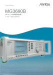
1
SERIES MG369XB SYNTHESIZED SIGNAL GENERATORS OPERATION MANUAL 490 JARVIS DRIVE MORGAN HILL, CA 95037-2809 P/N: 10370-10365 REVISION: D PRINTED: MARCH 2007 COPYRIGHT 2007 ANRITSU CO. WARRANTY The Anritsu product(s) listed on the title page is (are) warranted against defects in materials and workmanship for three years from the date of shipment. Anritsu's obligation covers repairing or replacing products which prove to be defective during the warranty period. Buyers shall prepay transportation charges for equipment returned to Anritsu for warranty repairs. Obligation is limited to the original purchaser. Anritsu is not liable for consequential damages. LIMITATION OF WARRANTY The foregoing warranty does not apply to Anritsu connectors that have failed due to normal wear. Also, the warranty does not apply to defects resulting from improper or inadequate maintenance by the Buyer, unauthorized modification or misuse, or operation outside of the environmental specifications of the product. No other warranty is expressed or implied, and the remedies provided herein are the Buyer's sole and exclusive remedies. TRADEMARK ACKNOWLEDGMENTS Adobe Acrobat is a registered trademark of Adobe Systems Incorporated. NOTICE Anritsu Company has prepared this manual for use by Anritsu Company personnel and customers as a guide for the proper installation, operation, and maintenance of Anritsu Company equipment and computer programs. The drawings, specifications, and information contained herein are the property of Anritsu Company, and any unauthorized use or disclosure of these drawings, specifications, and information is prohibited; they shall not be reproduced, copied, or used in whole or in part as the basis for manufacture or sale of the equipment or software programs without the prior written consent of Anritsu Company. UPDATES Updates to this manual, if any, may be downloaded from the Anritsu Internet site at: http://www.us.anritsu.com Safety Symbols To prevent the risk of personal injury or loss related to equipment malfunction, Anritsu Company uses the following symbols to indicate safety-related information. For your own safety, please read the information carefully BEFORE operating the equipment. WARNING WARNING indicates a hazard. It calls attention to a procedure that could result in personal injury or loss of life if not performed properly. Do not proceed beyond a WARNING notice until the indicated conditions are fully understood and met. CAUTION CAUTION indicates a hazard. It calls attention to a procedure which, if not performed properly, could result in damage to or destruction of a component of the instrument. Do not proceed beyond a CAUTION note until the indicated conditions are fully understood and met. The instrument is marked with this symbol to indicate that it is necessary for the user to refer to the instructions in the operation manual. Indicates ground. MG369XB OM Safety-1 For Safety WARNING When supplying power to this equipment, always use a three-wire power cable connected to a three-wire power line outlet. If power is supplied without grounding the equipment in this manner, there is a risk of receiving a severe or fatal electric shock. WARNING Before changing the fuse, always remove the power cord from the power outlet. There is the risk of receiving a fatal electric shock if the fuse is replaced with the power cord connected. Always use a new fuse of the type and rating specified by the fuse markings on the rear panel of the instrument. WARNING There are no operator serviceable components inside. Refer servicing of the instrument to qualified service technicians. To prevent the risk of electrical shock or damage to precision components, do not remove the equipment covers. WARNING If the equipment is used in a manner not specified by the manufacturer, the protection provided by the equipment may be impaired. Safety-2 MG369XB OM Table of Contents Chapter 1 General Information 1-1 Scope of Manual . . . . . . . . . . . . . . . . . . . . . . . . . . . . 1-3 1-2 Introduction . . . . . . . . . . . . . . . . . . . . . . . . . . . . . . 1-3 1-3 Description . . . . . . . . . . . . . . . . . . . . . . . . . . . . . . . 1-3 1-4 Identification Number . . . . . . . . . . . . . . . . . . . . . . . . . 1-3 1-5 Electronic Manual . . . . . . . . . . . . . . . . . . . . . . . . . . . 1-4 1-6 Related Manuals . . . . . . . . . . . . . . . . . . . . . . . . . . . . 1-4 GPIB Programming Manual . . . . . . . . . . . . . . . . . 1-4 Maintenance Manual . . . . . . . . . . . . . . . . . . . . . 1-4 1-7 Options . . . . . . . . . . . . . . . . . . . . . . . . . . . . . . . . . 1-4 1-8 Performance Specifications . . . . . . . . . . . . . . . . . . . . . . 1-7 1-9 Recommended Test Equipment . . . . . . . . . . . . . . . . . . . . 1-7 Chapter 2 Installation 2-1 Introduction . . . . . . . . . . . . . . . . . . . . . . . . . . . . . . 2-3 2-2 Initial Inspection . . . . . . . . . . . . . . . . . . . . . . . . . . . . 2-3 2-3 Preparation For Use . . . . . . . . . . . . . . . . . . . . . . . . . . 2-3 2-4 Rack Mounting Kit Installation . Preliminary . . . . . . . . Procedure . . . . . . . . . Power Requirements . . . . Power Connection . . . . . Standby Operation . . . . . Warmup Time . . . . . . . Operating Environment . . . . . . . . . . . . . . . . . . 2-5 GPIB Setup and Interconnection. . Interface Connector . . . . . . Cable Length Restrictions . . . GPIB Interconnection . . . . . Setting the GPIB Address . . . Selecting the Line Terminator . Interface Language . . . . . . . . . . . . . MG369XB OM . . . . . . . . . . . . . . . . . . . . . . . . . . . . . . . . . . . . . . . . . . . . . . . . . . . . . . . . . . . . . . . . . . . . . . . . . . . . . . . . . . . . . . . . . . . . . . . . . . . . . . . . . . . . . . . . . . . . . . . . . . . . . . . . . . . . . . . . . . . . . . . . . . . . . . . . . . . . . . . . . . . . . . . . . . . . . . . . . . . . . . . . . . . . . . . . . . . . . . . . . . . . . . . . . . . . . . . . . . . . . . 2-5 2-5 2-5 2-8 2-8 2-9 2-9 2-9 2-10 2-10 2-10 2-10 2-11 2-12 2-12 i Table of Contents (Continued) 2-6 Preparation for Storage/Shipment . . . . . . . . . . . . . . . . . . 2-13 Preparation for Storage . . . . . . . . . . . . . . . . . . . 2-13 Preparation for Shipment . . . . . . . . . . . . . . . . . . 2-13 2-7 Anritsu Service Centers . . . . . . . . . . . . . . . . . . . . . . . 2-14 Chapter 3 Local (Front Panel) Operation ii 3-1 Introduction . . . . . . . . . . . . . . . . . . . . . . . . . . . . . . 3-5 Typographic Conventions . . . . . . . . . . . . . . . . . . . 3-5 3-2 Front Panel Layout. . . . . . . . Line Key . . . . . . . . . . Data Display Area . . . . . Data Entry Area . . . . . . RF Output Control Key . . . RF Output Connector. . . . 3-3 Data Display Area . . . . . . . . . . . . . . . . . . . . . . . . . . . 3-8 Menu Display Format . . . . . . . . . . . . . . . . . . . . 3-9 Menu Keys . . . . . . . . . . . . . . . . . . . . . . . . . 3-10 3-4 Data Entry Area . . . . . . . . . . . . . . . . . . . . . . . . . . . 3-12 3-5 Instrument Start-Up . . . . . . . . . Powering Up the MG369XB . . . Start-Up Display . . . . . . . . Standby Operation . . . . . . . Self-Testing the MG369XB . . . Resetting to Default Parameters . . . . . . . . . . . . . . . . . . . . . . . . . . . . . . . . . . . . . . . . . . . . . . . . . . . . . . . . . . . . . . . . . . . . . . . . . . . . . . . . . . . . . . . 3-14 3-14 3-14 3-14 3-15 3-15 3-6 Entering Data . . . . . . . . . . Opening the Parameter . . Editing the Current Value . Entering a New Value . . . . . . . . . . . . . . . . . . . . . . . . . . . . . . . . . . . . . . . . . . . . . . . . . . . . . . . . . . . . . . . . . . . . . . . . . 3-17 3-17 3-18 3-19 3-7 CW Frequency Operation. . . . . Selecting CW Mode . . . . . Selecting a CW Frequency . . Selecting a Power Level . . . CW Ramp . . . . . . . . . . Phase Offset . . . . . . . . Electronic Frequency Control . . . . . . . . . . . . . . . . . . . . . . . . . . . . . . . . . . . . . . . . . . . . . . . . . . . . . . . . . . . . . . . . . . . . . . . . . . . . . . . . . . . . . . . . . . . . . . . . . . . . . . . . . . . . . . . . . . 3-20 3-20 3-20 3-22 3-23 3-24 3-25 . . . . . . . . . . . . . . . . . . . . . . . . . . . . . . . . . . . . . . . . . . . . . . . . . . . . . . . . . . . . . . . . . . . . . . . . . . . . . . . . . . . . . . . . . . . . . . . . . . . . . . . . 3-6 3-6 3-6 3-7 3-7 3-7 MG369XB OM Table of Contents (Continued) 3-8 Sweep Frequency Operation . . . . . . . . . . . . . Analog Sweep Mode . . . . . . . . . . . . . . Selecting Analog Sweep Mode . . . . . . . . . Setting Sweep Time . . . . . . . . . . . . . . Step Sweep Mode . . . . . . . . . . . . . . . Selecting Step Sweep Mode . . . . . . . . . . Setting Step Size, Dwell Time, and Sweep Time Selecting a Sweep Trigger . . . . . . . . . . . Manual Sweep Mode . . . . . . . . . . . . . Selecting Manual Sweep Mode. . . . . . . . . Selecting a Sweep Range . . . . . . . . . . . Selecting a Power Level . . . . . . . . . . . . Frequency Markers . . . . . . . . . . . . . . Selecting Alternate Sweep Mode . . . . . . . . List Sweep Mode . . . . . . . . . . . . . . . Selecting List Sweep Mode . . . . . . . . . . List Frequency Editing . . . . . . . . . . . . List Power Editing . . . . . . . . . . . . . . Selecting a List Sweep Range . . . . . . . . . Selecting a List Sweep Trigger . . . . . . . . . . . . . . . . . . . . . . . . . . . . . . . . . . . . . . . . . . . . . . . . . . . . . . . . . . . . . . . . . . . . . . . . . . . . . . . . . . . . . . . . . . . . . . . . . . . . . . . . . . . . . . . . . . . . . . . . . . . . . . . . . . . . . . . . . . . . . . . . . . . . . 3-26 3-26 3-26 3-27 3-28 3-28 3-29 3-31 3-32 3-33 3-33 3-36 3-36 3-38 3-42 3-43 3-45 3-46 3-48 3-49 3-9 Fixed Power Level Operation. . . . . . Selecting Fixed Power Level Mode . Selecting a Power Level . . . . . . Level Offset . . . . . . . . . . . . . . . . . . . . . . . . . . . . . . . . . . . . . . . . . 3-51 3-51 3-51 3-54 3-10 Power Level Sweep Operation . . . . . . . . . . . . . . . . . . Selecting CW Power Sweep Mode . . . . . . . . . . . . Setting CW Power Sweep Step Size and Dwell Time . . . Selecting a CW Power Sweep Trigger . . . . . . . . . . Selecting a Power Level Sweep Range . . . . . . . . . . Selecting a Sweep Frequency/Step Power Mode . . . . . Setting Power Level Step Size . . . . . . . . . . . . . . . . . . . . . . . . . . . . 3-56 3-56 3-57 3-57 3-59 3-61 3-62 3-11 Leveling Operations . . . . . . Selecting a Leveling Mode . Attenuator Decoupling . . ALC Power Slope . . . . . User Cal (User Power Level . . . . . . . . . . 3-63 3-63 3-67 3-68 3-70 MG369XB OM . . . . . . . . . . . . . . . . . . . . . . . . . . . . . . . . . . . . . . . . . . . . . . . . . . . . . . . . . . . . . . . . . . . . . . Flatness Calibration) . . . . . . . . . . . . . . . . . . . . . iii Table of Contents (Continued) 3-12 System Configuration. . . . . . . . . . . . . . . Accessing the System Configuration Menu . Configuring the Front Panel . . . . . . . Configuring the Rear Panel . . . . . . . . Configuring the RF . . . . . . . . . . . . Configuring the GPIB . . . . . . . . . . . Setting Increment Sizes . . . . . . . . . . . . . . . . . . . . . . . . . . . . . . . . . . . . . . . . . . . . . . . . . . . . . . . . . . . . . . . . . . . . . . . . . . 3-76 3-76 3-77 3-78 3-79 3-81 3-84 3-13 Saving/Recalling Instrument Setups. Saving Setups . . . . . . . . . . Recalling Setups . . . . . . . . Erasing Stored Setups. . . . . . . . . . . . . . . . . . . . . . . . . . . . . . . . . . . . . . . . . . . 3-85 3-85 3-86 3-86 . . . . . . . . . . . . . . . . . . . . . 3-14 Secure Operation . . . . . . . . . . . . . . . . . . . . . . . . . . . 3-87 Memory Profile and Security Issues . . . . . . . . . . . . . 3-87 3-15 Reference Loop Adjustments . . . . . . . . . . . . . . . . . . . . . 3-88 Reference Oscillator Calibration . . . . . . . . . . . . . . . 3-88 Reference Loop Bandwidth . . . . . . . . . . . . . . . . . 3-90 3-16 Signal Modulation . . . . . . . . . . . . . . . . . . . . . . . . . . 3-92 Accessing Modulation Modes . . . . . . . . . . . . . . . . 3-92 Amplitude Modulation Operating Modes . . . . . . . . . . . 3-93 Providing Amplitude Modulation . . . . . . . . . . . . . . 3-93 Frequency Modulation Operating Modes . . . . . . . . . . . 3-96 Providing Frequency Modulation . . . . . . . . . . . . . . 3-97 Phase Modulation Operating Modes . . . . . . . . . . . . 3-101 Providing Phase Modulation . . . . . . . . . . . . . . . . 3-102 Pulse Modulation Operating Modes. . . . . . . . . . . . . 3-106 Providing Pulse Modulation . . . . . . . . . . . . . . . . 3-107 3-17 Internal Power Meter (Option 8) . . . . . . . . . . . . . . . . . . 3-116 3-18 Scan Modulation (Option 20) . . . . . . . . . . . . . . . . . . . . 3-119 Chapter 4 Local Operation—Menu Maps iv 4-1 Introduction . . . . . . . . . . . . . . . . . . . . . . . . . . . . . . 4-3 4-2 Menu Map Description. . . . . . . . . . . . . . . . . . . . . . . . . 4-3 MG369XB OM Table of Contents (Continued) Chapter 5 Operation Verification 5-1 Introduction . . . . . . . . . . . . . . . . . . . . . . . . . . . . . . 5-3 5-2 Test Equipment . . . . . . . . . . . . . . . . . . . . . . . . . . . . 5-3 5-3 Test Records . . . . . . . . . . . . . . . . . . . . . . . . . . . . . . 5-4 5-4 Initial MG369XB Checkout . . . Power Up . . . . . . . . . Self-Test . . . . . . . . . . Resetting the MG369XB . . Warmup Time . . . . . . . 5-5 Frequency Synthesis Test . . . . . . . . . . . . . . . . . . . . . . . 5-5 Test Setup . . . . . . . . . . . . . . . . . . . . . . . . . . 5-5 Test Procedure . . . . . . . . . . . . . . . . . . . . . . . . 5-5 5-6 Level Accuracy and Flatness Tests. . . . . . . . Test Setup . . . . . . . . . . . . . . . . Power Level Accuracy Test Procedure . . . Power Level Flatness Test Procedure . . . . . . . . . . . . . . . . . . . . . . . . . . . . . . . . . . . . . . . . . . . . . . . . . . . . . . . . . . . . . . . . . . . . . . . . . . . . . . . . . . . . . . . . . . . . . . . . . . . . . . . . . . . . . . . . . . . . . . . . . . . . . . . 5-4 5-4 5-4 5-4 5-4 5-10 5-10 5-11 5-12 Chapter 6 Operator Maintenance 6-1 Introduction . . . . . . . . . . . . . . . . . . . . . . . . . . . . . . 6-3 6-2 Error and Warning/Status Messages . . . . . . . . . . . . . . . . . 6-3 Self-Test Error Messages . . . . . . . . . . . . . . . . . . . 6-3 Normal Operation Error and Warning/Status Messages . . . . 6-8 6-3 Troubleshooting . . . . . . . . . . . . . . . . . . . . . . . . . . . . 6-11 6-4 Routine Maintenance . . . . . . Cleaning the Fan Filters. . Cleaning the Data Display. Replacing the Line Fuses . MG369XB OM . . . . . . . . . . . . . . . . . . . . . . . . . . . . . . . . . . . . . . . . . . . . . . . . . . . . . . . . . . . . . . . . . . . . . . 6-14 6-14 6-14 6-14 v Table of Contents (Continued) Chapter 7 Use With Other Instruments 7-1 Introduction . . . . . . . . . . . . . . . . . . . . . . . . . . . . . . 7-3 7-2 Master-Slave Operation . . . . . . . . . . Connecting the Instruments . . . . . Initiating Master-Slave Operation . . Master-Slave Operation. . . . . . . . Master-Slave Operation in VNA Mode Terminating Master-Slave Operation . 7-3 Use with a 56100A Scalar Network Analyzer . . . . . . . . . . . . 7-10 Connecting the MG369XB to the 56100A . . . . . . . . . . 7-10 7-4 Use with a 8003 Scalar Network Analyzer . . . Connecting the MG369XB to the 8003 . . . Setting Up the MG369XB . . . . . . . . . Initiating 8003 SNA Operation . . . . . . . . . . . . . . . . . . . . . . . . . . . . . . . . . . . . . . . . . . . 7-11 7-11 7-12 7-13 7-5 Use with a HP8757D Scalar Network Analyzer. Connecting the MG369XB to a HP8757D . Setting Up the MG369XB . . . . . . . . . Initiating HP8757D SNA Operation . . . . . . . . . . . . . . . . . . . . . . . . . . . . . . . . . . . . . . . . . 7-15 7-15 7-16 7-18 7-6 IF Up-Conversion (Option 7) . . . . . . . . . . . . . . . . . . . . . 7-19 MG369XB Mixer Setup . . . . . . . . . . . . . . . . . . . 7-20 7-7 mmWave Source Modules . . . . . . . . . . . . . . . . . . . . . . 7-21 . . . . . . . . . . . . . . . . . . . . . . . . . . . . . . . . . . . . . . . . . . . . . . . . . . . . . . . . . . . . . . . . . . . . . . . . . . 7-4 7-4 7-5 7-7 7-7 7-9 Appendix A Rear Panel Connectors A-1 Introduction . . . . . . . . . . . . . . . . . . . . . . . . . . . . . . A-1 A-2 Rear Panel Connectors . . . . . . . . . . . . . . . . . . . . . . . . A-1 A-3 Connector Pin-out Diagrams . . . . . . . . . . . . . . . . . . . . . A-1 Appendix B Performance Specifications Subject Index vi MG369XB OM Chapter 1 General Information Table of Contents 1-1 Scope of Manual . . . . . . . . . . . . . . . . . . . . . . . . . . . . 1-3 1-2 Introduction . . . . . . . . . . . . . . . . . . . . . . . . . . . . . . 1-3 1-3 Description . . . . . . . . . . . . . . . . . . . . . . . . . . . . . . . 1-3 1-4 Identification Number . . . . . . . . . . . . . . . . . . . . . . . . . 1-3 1-5 Electronic Manual . . . . . . . . . . . . . . . . . . . . . . . . . . . 1-4 1-6 Related Manuals . . . . . . . . . . . . . . . . . . . . . . . . . . . . 1-4 GPIB Programming Manual . . . . . . . . . . . . . . . . . 1-4 Maintenance Manual . . . . . . . . . . . . . . . . . . . . . 1-4 1-7 Options . . . . . . . . . . . . . . . . . . . . . . . . . . . . . . . . . 1-4 1-8 Performance Specifications . . . . . . . . . . . . . . . . . . . . . . 1-7 1-9 Recommended Test Equipment . . . . . . . . . . . . . . . . . . . . 1-7 Figure 1-1. 1-2 Series MG369XB Synthesized Signal Generator MG369XB OM Chapter 1 General Information 1-1 Scope of Manual This manual provides general information, installation, and operating information for the Anritsu series MG369XB synthesized signal generator. Throughout this manual, the terms MG369XB, signal generator, and synthesizer will be used interchangeably to refer to the instrument. Manual organization is shown in the table of contents. 1-2 Introduction This chapter contains general information about the series MG369XB signal generators. It includes a general description of the instrument and information on its identification number, related manuals, options, and performance specifications. A listing of recommended test equipment is also provided. 1-3 Description The series MG369XB synthesized signal generators are microprocessor-based, synthesized signal sources with high resolution phase-lock capability. They generate both discrete CW frequencies and broad (full range) and narrow band step sweeps across the frequency range of 2 GHz to 67 GHz. Options are available to extend the low end of the frequency range to 0.1 Hz. All functions of the signal generator are fully controllable locally from the front panel or remotely (except for power on/standby) via the IEEE-488 General Purpose Interface Bus (GPIB). Table 1-1, page 1-5, lists models, frequency ranges, and maximum leveled output. 1-4 Identification Number All Anritsu instruments are assigned a unique six-digit ID number, such as “020312”. The ID number is imprinted on a decal that is affixed to the rear panel of the unit. Special-order instrument configurations also have an additional specials number tag attached to the rear panel of the unit, such as SM1234. When ordering parts or corresponding with Anritsu Customer Service, please use the correct serial number with reference to the specific instrument's model number (for example, model MG3693B synthesized signal generator, serial number: 020312). MG369XB OM 1-3 Options General Information 1-5 Electronic Manual Updated manuals are available for download from the document area of the Anritsu web site at: http://www.us.anritsu.com. 1-6 Related Manuals This is one of a three manual set that consists of an operation manual, a GPIB programming manual, and a maintenance manual. 1-7 1-4 Options GPIB Programming Manual The Series MG369XB Synthesized Signal Generator GPIB Programming Manual provides information for remote operation of the signal generator with product specific commands sent from an external controller via the IEEE 488 General Purpose Interface Bus (GPIB). It contains a general description of the GPIB and bus data transfer and control functions, a complete listing and description of all MG369XB GPIB product specific commands, and several programming examples. The Anritsu part number for the GPIB programming manual is 10370-10366. Maintenance Manual The Series MG369XB Synthesized Signal Generator Maintenance Manual supplies service information for all models in the MG369XB series. The service information includes functional circuit descriptions, block diagrams, performance verification tests, calibration procedures, troubleshooting data, and assembly and component removal/replacement procedures. The Anritsu part number for the maintenance manual is 10370-10367. The series MG369XB synthesizer provides a wide array of instrument configurations through a series of base model and option choices. Table 1-1, on page 1-5, lists the available models with frequency ranges. Refer to Appendix B, MG3690B RF/Microwave Signal Generators Technical Datasheet, P/N: 11410-00344, for current information. MG369XB OM General Information Table 1-1. Options Series MG369XB Model and Option List (1 of 2) Model Number Configuration Frequency Range MG3691B With Option 4 or 5 Standard ³0.01 – £10.0 GHz ³2.0 – £10.0 GHz MG3692B With Option 4 or 5 Standard ³0.01 – £20.0 GHz ³2.0 – £20.0 GHz MG3693B With Option 4 or 5 Standard ³0.01 – £30.0 GHz ³2.0 – £30.0 GHz MG3694B With Option 4 or 5 Standard ³0.01 – £40.0 GHz ³2.0 – £40.0 GHz MG3695B With Option 4 or 5 Standard ³0.01 – £50.0 GHz ³2.0 – £50.0 GHz MG3696B With Option 4 or 5 Standard ³0.01 – £67.0 GHz* ³2.0 – £67.0 GHz* *Operational to 70.0 GHz Options List Option 1A: Rack Mounting with Slides—Rack mount kit containing a set of track slides (90° tilt capability), mounting ears, and front panel handles for mounting the instrument in a standard 19-inch equipment rack. Option 1B: Rack Mounting without Slides—Modifies rack mounting hardware to install unit in a console that has mounting shelves. Includes mounting ears and front panel handles. Option 2X: 110 dB Mechanical Step Attenuator—Adds a 10 dB per step attenuator with a 110 dB range. Output power is selected directly in dBm on the front panel (or via GPIB). Rated RF output power is reduced. Option 2E: 120 dB Electronic Step Attenuator—Adds a 10 dB per step attenuator with a 120 dB range for models having a high-end frequency of £20 GHz. Output power is selected directly in dBm on the front panel (or via GPIB). Rated RF output power is reduced. Option 3: Ultra-Low Phase Noise—Adds new modules that significantly reduces single-sideband phase noise, ³2 GHz. Option 4: Digital Down Converter—Adds a digital down converter for ultra-low phase noise for 0.01 to 2.2 GHz RF coverage. Option 5: Analog Down Converter—Adds an analog down converter for 0.01 to 2.0 GHz RF coverage. Option 6: Analog Sweep Capability—Adds analog sweep capability. (Limited to ³500 MHz when used with Option 4.) Option 7: IF Up-Conversion—Adds an internal 40 GHz mixer for up-converting an IF signal. Not available in MG3695B, MG3696B, or with Option 18. Option 8: Power Monitor—Adds internal power measurement capability. (Not available with Option 9.) Option 9X: Rear Panel RF Output—Moves the RF output connector to the rear panel. Option 10: User-Defined Modulation Waveform Software—Adds a software package that provides the ability to serially (or via GPIB) download user-defined waveforms into the memory of the internal waveform generator. Requires an external PC and an instrument with an internal low frequency generator (Option 23). MG369XB OM 1-5 Options Table 1-1. General Information Series MG369XB Model and Option List (2 of 2) Option 12: Option 13X*: Option 14: Option 15X: External Frequency and Phase Modulation—Adds external FM/FM capabilities via a rear panel BNC connector. Requires an external modulating signal input or an internal low frequency generator (Option 23). External Pulse Modulation—Adds external pulse modulation capability via a rear panel BNC connector. Requires an external modulating signal input. Amplitude Modulation—Adds external AM capability via a rear panel BNC connector. Requires an external modulating signal input or an internal low frequency generator (Option 23). High Power Output—Adds high-power RF components to the instrument providing increased RF output power. Option 16: High-Stability Time Base—Adds an ovenized 10 MHz crystal oscillator with frequency stability of <5 x 10⁻¹⁰/day. Option 17: Delete Front Panel—Deletes the front panel for use in remote control applications where a front panel display or keyboard control are not needed. Option 18: mmW Bias Output—Adds a rear panel BNC Twinax connector to bias the 5400-xWRxx millimeter wave source modules. Option 20: Scan Modulation—Adds an internal Scan modulator for simulating high-depth amplitude modulated signals. Requires an external modulating signal input capability. (Not available on models MG3693B, MG3694B, MG3695B, MG3696B, or with Options 2E, 7, 15X, or 22.) Option 22: 0.1 Hz to 10.0 MHz Audio Frequency—Adds frequency coverage below 10 MHz. The frequency resolution below 10 MHz is 0.02 Hz. Rated RF output power is reduced. Option 23*: Low Frequency Generator—Provides modulation waveforms for internal AM, FM, or FM. Not available without Option 12 or 14. Option 24*: Internal Pulse Generator—Provides pulse waveforms for internal pulse modulation. Not available without Option 13. Option 25X*: Analog Modulation Suite—The analog modulation suite bundles Options 12, 13, 14, 23 and 24, offering internal and external AM, FM, FM, and pulse modulation. Option 26X*: Pulse Modulation—Adds external pulse modulation via a rear panel BNC connector. For internal modulation capability, requires additionally Pulse Generator, Option 27. (This option comes in different versions based on instrument configuration.) Option 27*: LF Generator—Provides modulation waveforms for internal AM, FM, FM, and Pulse. (Not available without Option 12, 14, or 26.) Option 28X*: Analog Modulation Suite—For ease of ordering and package pricing, this option bundles Options 12, 14, 26 and 27, offering internal and external AM, FM, FM, and Pulse Modulation. (This option comes in different versions , based on instrument configuration.) Option 30: Low Phase Noise * May not be availlable for all instruments or may require additional upgrades. Contact Anritsu customer service for details. 1-6 MG369XB OM General Information Recommended Test Equipment 1-8 Performance Specifications The series MG369XB synthesized signal generator performance specifications are provided in Appendix B. 1-9 Recommended Test Equipment Table 1-2 lists the recommended test equipment for performing the series MG369XB synthesized signal generator operation verification tests in Chapter 5. Table 1-2. Instrument Frequency Counter Recommended Test Equipment Critical Specification Recommended Manufacturer/Model Range: 0.01 to 40 GHz Input Z: 50W Resolution: 1 Hz Other: External Time Base Input Anritsu Model MF2414B Range: 0.01 to 65 GHz Input Z: 50W Resolution: 1 Hz Other: External Time Base Input EIP Microwave, Inc. Models 538B, 548B, or 578B, with Cable Kit: Option 590 and External Mixer: Option 91 (26.5 to 40 GHz) Option 92 (40 to 60 GHz) Option 93 (60 to 90 GHz) or Frequency Counter with Cable Kit and External Mixer MG369XB OM Power Meter, Range: –30 to +20 dBm with (1mW to 100 mW) Power Sensor Anritsu Model ML2437A or ML2438A, with Power Sensor: MA2474A (0.01 to 40 GHz) MA2575A (0.01 to 50 GHz) Oscilloscope Tektronix, Inc. Model TAS485 Bandwidth: DC to 150 MHz Vertical Sensitivity: 2 mV/ division Horizontal Sensitivity: 50 ns/ division 1-7/1-8 Chapter 2 Installation Table of Contents 2-1 Introduction . . . . . . . . . . . . . . . . . . . . . . . . . . . . . . 2-3 2-2 Initial Inspection . . . . . . . . . . . . . . . . . . . . . . . . . . . . 2-3 2-3 Preparation For Use . . . . . . . . . . . . . . . . . . . . . . . . . . 2-3 2-4 Rack Mounting Kit Installation . Preliminary . . . . . . . . Procedure . . . . . . . . . Power Requirements . . . . Power Connection . . . . . Standby Operation . . . . . Warmup Time . . . . . . . Operating Environment . . . . . . . . . . . . . . . . . . 2-5 GPIB Setup and Interconnection. . Interface Connector . . . . . . Cable Length Restrictions . . . GPIB Interconnection . . . . . Setting the GPIB Address . . . Selecting the Line Terminator . Interface Language . . . . . . . . . . . . . 2-6 Preparation for Storage/Shipment . . . . . . . . . . . . . . . . . . 2-13 Preparation for Storage . . . . . . . . . . . . . . . . . . . 2-13 Preparation for Shipment . . . . . . . . . . . . . . . . . . 2-13 2-7 Anritsu Service Centers . . . . . . . . . . . . . . . . . . . . . . . 2-14 . . . . . . . . . . . . . . . . . . . . . . . . . . . . . . . . . . . . . . . . . . . . . . . . . . . . . . . . . . . . . . . . . . . . . . . . . . . . . . . . . . . . . . . . . . . . . . . . . . . . . . . . . . . . . . . . . . . . . . . . . . . . . . . . . . . . . . . . . . . . . . . . . . . . . . . . . . . . . . . . . . . . . . . . . . . . . . . . . . . . . . . . . . . . . . . . . . . . . . . . . . . . . . . . . . . . . . . . . . . . . . 2-5 2-5 2-5 2-8 2-8 2-9 2-9 2-9 2-10 2-10 2-10 2-10 2-11 2-12 2-12 Chapter 2 Installation 2-1 Introduction This chapter provides installation instructions for the series MG369XB synthesized signal generator. It includes information on initial inspection, preparation for use, storage, reshipment, and General Purpose Interface Bus (GPIB) setup and interconnections. 2-2 Initial Inspection Inspect the shipping container for damage. If the shipping container or cushioning material is damaged, retain until the contents of the shipment have been checked against the packing list and the signal generator has been checked for mechanical and electrical operation. If the shipment is incomplete or if the signal generator is damaged mechanically or electrically, notify your local sales representative or Anritsu Customer Service. If either the shipping container is damaged or the cushioning material shows signs of stress, notify the carrier as well as Anritsu. Keep the shipping materials for the carrier's inspection. 2-3 Preparation For Use MG369XB OM Preparation for use consists of installing the instrument into a suitable operating location and connecting the signal generator to a power source. The following paragraphs provide these procedures along with information about power requirements, warmup times, and the operating environment. Figure 2-1, on the following page, illustrates the basic outer dimensions of the instrument. 2-3 Preparation For Use Figure 2-1. 2-4 Installation MG369XB Outline Dimensions (in millimeters) MG369XB OM Installation 2-4 Rack Mounting Kit Installation Rack Mounting Kit Installation The rack mounting kit (Option 1A) contains a set of track slides (90° tilt capability), mounting ears, and front panel handles for mounting the signal generator in a standard equipment rack. The following procedure provides instructions for installing the rack mounting hardware on to the instrument. The rack mounting kit (Option 1B) uses the same inner assembly without the slide. This procedure may also be used for installing the Option 1B rack mount assembly. Refer to Figures 2-3 and 2-4 during this procedure. Preliminary Disconnect the power cord and any other cables from the instrument. Procedure Install the rack mounting hardware as follows: Step 1. Using a Phillips screwdriver, remove the screws and the front handle assemblies from the instrument. (For instruments not having front handles, remove the screws and the front top and bottom feet from the instrument.) Retain the screws. Step 2. Remove the four feet from the rear of the instrument. Retain the screws. Rear Feet (4) Figure 2-3. MG369XB OM Front Handle and Feet Removal 2-5 Rack Mounting Kit Installation NOTE The screws with green heads have metric threads. When it becomes necessary to replace any of these screws, always use the exact replacement green-headed screws to avoid damage to the instrument. An rit su P /N’s: 905-8 (long); Z-951102 (short). Figure 2-4. 2-6 Installation Step 3. Remove the inner slide assemblies from the outer slide assemblies. Step 4. Place the left side inner slide assembly onto the instrument case with the handle towards the front of the instrument (Figure 2-4). Step 5. Insert two green-headed screws through the holes in the slide assembly behind the handle and into the metric tapped holes in the side of the instrument. Step 6. Insert two green-headed screws through the holes near the rear of the slide assembly and into the metric tapped holes in the side of the instrument. Step 7. Insert the two SAE threaded screws (removed from the feet) through the 90° tabs on the rear of the slide assembly and into the rear panel of the instrument. Step 8. Using the Phillips screwdriver, tighten all screws holding the left side slide assembly to the instrument chassis. Rack Mounting Hardware Installation MG369XB OM Installation Rack Mounting Kit Installation Step 9. Place the right side inner slide assembly onto the instrument case with the handle towards the front of the instrument. Step 10. Insert two green-headed screws through the holes in the slide assembly behind the handle and into the metric tapped holes in the side of the instrument. Step 11. Insert two green-headed screws through the holes near the rear of the slide assembly and into the metric tapped holes in the side of the instrument. Step 12. Insert the two SAE threaded screws (removed from the feet) through the 90° tabs on the rear of the slide assembly and into the rear panel of the instrument. Step 13. Using the Phillips screwdriver, tighten all screws holding the right side slide assembly to the instrument chassis. Step 14. Using the appropriate hardware, install the outer slide assemblies onto the equipment rack. Step 15. Lift the signal generator into position. Align the inner and outer slide assemblies and slide the instrument into the rack. Realign the hardware as needed for smooth operation. MG369XB OM 2-7 Rack Mounting Kit Installation Installation WARNING When supplying power to this equipment, always use a three-wire power cable connected to a three-wire power line outlet. If power is supplied without grounding the equipment in this manner, there is a risk of receiving a severe or fatal electric shock. Power Requirements The signal generator accepts 90 to 264 Vac, 48 to 440 Hz, single-phase power. Power consumption is 300 VA maximum. The signal generator is intended for Installation Category (Over Voltage Category) II. Power Connection To connect the MG369XB to the power source, plug the female end of the power cable into the input line voltage receptacle on the rear panel (Figure 2-2). Then plug the male end of the power cord into a three-wire power line outlet. Turn on the rear panel power switch. This automatically places the signal generator in operation (front panel OPERATE LED on). Figure 2-2. 2-8 Signal Generator Rear Panel Showing Power Connection MG369XB OM Installation Rack Mounting Kit Installation CAUTION Before installing the MG369XB in its operating environment, ensure that all airflow passages at the sides and rear of the instrument are clear. This is of particular importance whenever the unit is being rack-mounted. Keep the cooling fan filters clean so that the ventilation holes are not obstructed. A blocked fan filter can cause the instrument to overheat and shut down. Standby Operation Whenever the signal generator is not being used it should be left connected to the power source and placed in standby. This keeps the internal time base frequency reference at operating temperature. On the front panel, press LINE to switch the MG369XB from OPERATE (green LED on) to STANDBY (orange LED on). (Hold the LINE key down for at least ½ second to prevent power-off of the unit.) L in e O p e ra te S ta n d b y NOTE During standby operation, the fan runs continuously. L in e K e y Warmup Time From Standby–When placing the MG369XB in operation from standby, allow 30 minutes warmup to assure stable operation. From a Cold Start (0°C)–The signal generator requires approximately 120 hours (5 days) of warm up to achieve specified frequency stability with aging. NOTE Instruments disconnected from ac power for more than 72 hours require 30 days to return to specified aging. Operating Environment MG369XB OM The MG369XB can be operated within the following environmental limits. q Temperature: 0°C to 50°C q Humidity: 5 to 95% relative at 40°C q Altitude: up to 4600 meters q Cooling: Internal cooling is provided by forced airflow from the fans mounted on the rear panel 2-9 GPIB Setup and Interconnection 2-5 GPIB Setup and Interconnection Installation The MG369XB provides automated microwave signal generation via the GPIB. The following paragraphs provide information about interface connections, cable requirements, setting the GPIB operating parameters, and selecting the external interface language. Interface Connector Interface between the signal generator and other devices on the GPIB is via a 24-wire interface cable. This cable uses connector shells having two connector faces. These double-faced connectors allow for the parallel connection of two or more cables to a single device. Cable Length Restrictions The GPIB can accommodate up to 15 instruments at any one time. To achieve design performance on the bus, proper timing and voltage level relationships must be maintained. If either the cable length between separate instruments or the cumulative cable length between all instruments is too long, the data and control lines cannot be driven properly and the system may fail to perform. Cable length restrictions are as follows: q No more than 15 instruments may be installed on the bus q Total cumulative cable length (in meters) may not exceed two times the number of bus instruments or 20 meters—whichever is less NOTE For low EMI applications, the GPIB cable should be a fully shielded type with wellgrounded metal-shell connectors. GPIB Interconnection 2-10 The only interconnection required for GPIB operation is between the signal generator and the controller. This interconnection is via a standard GPIB cable. The Anritsu part number for such a cable is 2100-1, -2, or -4 (1, 2, or 4 meters in length). MG369XB OM Installation GPIB Setup and Interconnection Setting the GPIB Address The default GPIB address is five. If a different GPIB address is desired, it can be set from the front panel using the Configure GPIB menu. To change the GPIB address, first press the front panel main menu key labeled System . The System menu is displayed. Now press the menu soft-key Config . The System Configuration menu (shown below) is displayed. To access the Configure GPIB menu from this menu, press the menu soft-key GPIB > . The Configure GPIB menu (shown below) is displayed. Press the menu soft-key GPIB Address [ADD] to change the current GPIB address of the signal generator. Enter a new address using the cursor control keys or the data entry keypad and the terminator soft-key [ADR]. The new GPIB address will now appear on the display. The entry must be between 1 and 30 to be recognized as a valid GPIB address. MG369XB OM 2-11 GPIB Setup and Interconnection Selecting the Line Terminator Installation Data is delimited on the GPIB by either the carriage return (CR) ASCII character or both the carriage return and line feed (CR/LF) ASCII characters. Which character is used depends upon the requirements of the system controller. Most modern controllers can use either CR or CR/LF, while many older controllers require one or the other. Consult the controller's manual for its particular requirements. From the Configure GPIB menu display, you can select which GPIB terminator to use by pressing the menu soft-key GPIB Terminator . This menu soft-key toggles the GPIB terminator between CR and CR/LF. The current selection appears on the display. Interface Language 2-12 The series MG369XB synthesized signal generators can be remotely operated via the GPIB using an external interface language—Native. The Native interface language uses a set of MG369XB GPIB product specific commands to control the instrument. Detailed descriptions and a comprehensive list of these commands can be found in the MG369XB programming manual, P/N: 10370-10366. MG369XB OM Installation 2-6 Preparation for Storage/Shipment Preparation for Storage/Shipment The following paragraphs give instructions for preparing the MG369XB for storage or shipment. Preparation for Storage Preparing the signal generator for storage consists of cleaning the unit, packing the inside with moisture-absorbing desiccant crystals, and storing the unit in a temperature environment that is maintained between –40°C and +75°C. Preparation for Shipment To provide maximum protection against damage in transit, the signal generator should be repackaged in the original shipping container. If this container is no longer available and the unit is being returned to Anritsu for repair, advise Anritsu Customer Service; they will send a new shipping container free of charge. In the event neither of these two options is possible, instructions for packaging and shipment are given below. Use a Suitable Container Obtain a corrugated cardboard carton with a 125 kg test strength. This carton should have inside dimensions of no less than 15 cm larger than the unit dimensions to allow for cushioning (refer to Figure 2-1, page 2-4). Protect the Instrument Surround the unit with polyethylene sheeting to protect the finish. Cushion the Instrument Cushion the instrument on all sides by tightly packing dunnage or urethane foam between the carton and the unit. Provide at least three inches of dunnage on all sides. Seal the Container Seal the carton by using either shipping tape or an industrial stapler. Address the Container If the instrument is being returned to Anritsu for service, mark the address of the appropriate Anritsu service center (Table 2-1, following page) and your return address on the carton in one or more prominent locations. MG369XB OM 2-13 Anritsu Service Centers 2-7 Anritsu Service Centers Table 2-1. Installation Table 2-1, below, lists the contact information for Anritsu service centers around the world. Anritsu Service Centers UNITED STATES ANRITSU COMPANY 490 Jarvis Drive Morgan Hill, CA 95037-2809 Telephone: 1-800-ANRITSU FAX: 408-776-1744 FRANCE ANRITSU S.A 9 Avenue du Quebec Zone de Courtaboeuf 91951 Les Ulis Cedex Telephone: 016-09-21-550 FAX: 016-44-61-065 GERMANY ANRITSU COMPANY 10 New Maple Ave., Unit 305 Pine Brook, NJ 07058 Telephone: 1-800-ANRITSU FAX: 973-575-0092 ANRITSU GmbH Konrad-Zuse-Platz 1 81829 Muenchen, Germany Telephone: +49 89 4423080 FAX: +49 89 44230855 INDIA ANRITSU COMPANY 1155 E. Collins Blvd Richardson, TX 75081 Telephone: 1-800-ANRITSU FAX: 972-671-1877 AUSTRALIA ANRITSU PTY. LTD. Unit 21/270 Ferntree Gully Road Notting Hill, Victoria 3168 Australia Telephone: 03-9558-8177 FAX: 03-9558-8255 BRAZIL Anritsu Eletrônica Ltda. Praça Amadeu Amaral 27, 1º andar Bela Vista, São Paulo, SP, Brasil CEP: 01327-010 Telephone: 55-11-3283-2511 Fax: 55-11-3288-6940 CANADA ANRITSU INSTRUMENTS LTD. 700 Silver Seven Road, Suite 120 Kanata, Ontario K2V 1C3 Telephone: (613) 591-2003 FAX: (613) 591-1006 MEERA AGENCIES PVT. LTD. 23 Community Centre Zamroodpur, Kailash Colony Extension, New Delhi, India 110 048 Phone: 011-2-6442700/6442800 FAX : 011-2-644250023 ISRAEL TECH-CENT, LTD. 4 Raul Valenberg St Tel-Aviv 69719 Telephone: (03) 64-78-563 FAX: (03) 64-78-334 ITALY ANRITSU Sp.A Roma Office Via E. Vittorini, 129 00144 Roma EUR Telephone: (06) 50-99-711 FAX: (06) 50-22-425 KOREA ANRITSU CORPORATION LTD. 8F Hyunjuk Building, 832-41 Yeoksam Dong, Kangnam-Ku Seoul, South Korea 135-080 Telephone: 02-553-6603 FAX: 02-553-6605 JAPAN ANRITSU CUSTOMER SERVICES LTD. 5-1-1 Onna Atsugi-shi Kanagawa-Prf. 243 Japan Telephone: 0462-96-6688 FAX: 0462-25-8379 SINGAPORE ANRITSU (SINGAPORE) PTE LTD. 10, Hoe Chiang Road #07-01/02 Keppel Towers Singapore 089315 Telephone: 6-282-2400 FAX: 6-282-2533 SOUTH AFRICA ETECSA 12 Surrey Square Office Park 330 Surrey Avenue Ferndale, Randburg, 2194 South Africa Telephone: 27-11-787-7200 FAX: 27-11-787-0446 SWEDEN ANRITSU AB Borgafjordsgatan 13 164 40 KISTA, Sweden Telephone: +46-8-53470700 FAX: +46-8-53470730 TAIWAN ANRITSU CO., INC. 7F, No. 316, Section 1 NeiHu Road Taipei, Taiwan, R.O.C. Telephone: 886-2-8751-1816 FAX: 886-2-8751-2126 UNITED KINGDOM ANRITSU LTD. 200 Capability Green Luton, Bedfordshire LU1 3LU, England Telephone: 015-82-433200 FAX: 015-82-731303 CHINA ANRITSU ELECTRONICS (SHANGHAI) CO. LTD. 2F, Rm B, 52 Section Factory Building No. 516 Fu Te Rd (N) Shanghai 200131 P.R. China Telephone: 21-5868-0226 FAX: 21-5868-0588 2-14 MG369XB OM Chapter 3 Local (Front Panel) Operation Table of Contents 3-1 Introduction . . . . . . . . . . . . . . . . . . . . . . . . . . . . . . 3-5 Typographic Conventions . . . . . . . . . . . . . . . . . . . 3-5 3-2 Front Panel Layout. . . . . . . . Line Key . . . . . . . . . . Data Display Area . . . . . Data Entry Area . . . . . . RF Output Control Key . . . RF Output Connector. . . . 3-3 Data Display Area . . . . . . . . . . . . . . . . . . . . . . . . . . . 3-8 Menu Display Format . . . . . . . . . . . . . . . . . . . . 3-9 Menu Keys . . . . . . . . . . . . . . . . . . . . . . . . . 3-10 3-4 Data Entry Area . . . . . . . . . . . . . . . . . . . . . . . . . . . 3-12 3-5 Instrument Start-Up . . . . . . . . . Powering Up the MG369XB . . . Start-Up Display . . . . . . . . Standby Operation . . . . . . . Self-Testing the MG369XB . . . Resetting to Default Parameters . . . . . . . . . . . . . . . . . . . . . . . . . . . . . . . . . . . . . . . . . . . . . . . . . . . . . . . . . . . . . . . . . . . . . . . . . . . . . . . . . . . . . . . 3-14 3-14 3-14 3-14 3-15 3-15 3-6 Entering Data . . . . . . . . . . Opening the Parameter . . Editing the Current Value . Entering a New Value . . . . . . . . . . . . . . . . . . . . . . . . . . . . . . . . . . . . . . . . . . . . . . . . . . . . . . . . . . . . . 3-17 3-17 3-18 3-19 . . . . . . . . . . . . . . . . . . . . . . . . . . . . . . . . . . . . . . . . . . . . . . . . . . . . . . . . . . . . . . . . . . . . . . . . . . . . . . . . . . . . . . . . . . . . . . . . . . . . . . . . . . . . . . . . . . . . 3-6 3-6 3-6 3-7 3-7 3-7 Table of Contents (Continued) 3-2 3-7 CW Frequency Operation. . . . . Selecting CW Mode . . . . . Selecting a CW Frequency . . Selecting a Power Level . . . CW Ramp . . . . . . . . . . Phase Offset . . . . . . . . Electronic Frequency Control . . . . . . . . . . . . . . . . . . . . . . . . . . . . . . . . . . . . . . . . . . . . . . . . . . . . . . . . . . . . . . . . . . . . . . . . . . . . . . . . . . . . . 3-20 3-20 3-20 3-22 3-23 3-24 3-25 3-8 Sweep Frequency Operation . . . . . . . . . . . . . Analog Sweep Mode . . . . . . . . . . . . . . Selecting Analog Sweep Mode . . . . . . . . . Setting Sweep Time . . . . . . . . . . . . . . Step Sweep Mode . . . . . . . . . . . . . . . Selecting Step Sweep Mode . . . . . . . . . . Setting Step Size, Dwell Time, and Sweep Time Selecting a Sweep Trigger . . . . . . . . . . . Manual Sweep Mode . . . . . . . . . . . . . Selecting Manual Sweep Mode. . . . . . . . . Selecting a Sweep Range . . . . . . . . . . . Selecting a Power Level . . . . . . . . . . . . Frequency Markers . . . . . . . . . . . . . . Selecting Alternate Sweep Mode . . . . . . . . List Sweep Mode . . . . . . . . . . . . . . . Selecting List Sweep Mode . . . . . . . . . . List Frequency Editing . . . . . . . . . . . . List Power Editing . . . . . . . . . . . . . . Selecting a List Sweep Range . . . . . . . . . Selecting a List Sweep Trigger . . . . . . . . . . . . . . . . . . . . . . . . . . . . . . . . . . . . . . . . . . . . . . . . . . . . . . . . . . . . . . . . . . . . . . . . . . . . . . . . . . . . . . . . . . . . . . . . . . . . . . . . . . . . . . . . . . . . . . . . . . . . . . . . . . . . . . . . . . . . . . . . . . . . . 3-26 3-26 3-26 3-27 3-28 3-28 3-29 3-31 3-32 3-33 3-33 3-36 3-36 3-38 3-42 3-43 3-45 3-46 3-48 3-49 3-9 Fixed Power Level Operation. . . . . . Selecting Fixed Power Level Mode . Selecting a Power Level . . . . . . Level Offset . . . . . . . . . . . . . . . . . . . . . . . . . . . . . . . . . . . . . . . . . 3-51 3-51 3-51 3-54 3-10 Power Level Sweep Operation . . . . . . . . . . . . . . . . . . Selecting CW Power Sweep Mode . . . . . . . . . . . . Setting CW Power Sweep Step Size and Dwell Time . . . Selecting a CW Power Sweep Trigger . . . . . . . . . . Selecting a Power Level Sweep Range . . . . . . . . . . Selecting a Sweep Frequency/Step Power Mode . . . . . Setting Power Level Step Size . . . . . . . . . . . . . . . . . . . . . . . . . . . . 3-56 3-56 3-57 3-57 3-59 3-61 3-62 . . . . . . . . . . . . . . . . . . . . . . . . . . . . . . . . . . . . . . . . . . . . . . . . . . . . . . MG369XB OM Table of Contents (Continued) 3-11 Leveling Operations . . . . . . Selecting a Leveling Mode . Attenuator Decoupling . . ALC Power Slope . . . . . User Cal (User Power Level . . . . . . . . . . . . . . . . . . . . . . . . . . . . . . . . . . . . . . . . . . . . . Flatness Calibration) . . . . . . . . . . . . . . . . . . . . . . . . . . . . . . . 3-63 3-63 3-67 3-68 3-70 3-12 System Configuration. . . . . . . . . . . . . . . Accessing the System Configuration Menu . Configuring the Front Panel . . . . . . . Configuring the Rear Panel . . . . . . . . Configuring the RF . . . . . . . . . . . . Configuring the GPIB . . . . . . . . . . . Setting Increment Sizes . . . . . . . . . . . . . . . . . . . . . . . . . . . . . . . . . . . . . . . . . . . . . . . . . . . . . . . . . . . . . . . . . . . . . . . . . . 3-76 3-76 3-77 3-78 3-79 3-81 3-84 3-13 Saving/Recalling Instrument Setups. Saving Setups . . . . . . . . . . Recalling Setups . . . . . . . . Erasing Stored Setups. . . . . . . . . . . . . . . . . . . . . . . . . . . . . . . . . . . . . . . . . . . 3-85 3-85 3-86 3-86 . . . . . . . . . . . . . . . . . . . . . 3-14 Secure Operation . . . . . . . . . . . . . . . . . . . . . . . . . . . 3-87 Memory Profile and Security Issues . . . . . . . . . . . . . 3-87 3-15 Reference Loop Adjustments . . . . . . . . . . . . . . . . . . . . . 3-88 Reference Oscillator Calibration . . . . . . . . . . . . . . . 3-88 Reference Loop Bandwidth . . . . . . . . . . . . . . . . . 3-90 3-16 Signal Modulation . . . . . . . . . . . . . . . . . . . . . . . . . . 3-92 Accessing Modulation Modes . . . . . . . . . . . . . . . . 3-92 Amplitude Modulation Operating Modes . . . . . . . . . . . 3-93 Providing Amplitude Modulation . . . . . . . . . . . . . . 3-93 Frequency Modulation Operating Modes . . . . . . . . . . . 3-96 Providing Frequency Modulation . . . . . . . . . . . . . . 3-97 Phase Modulation Operating Modes . . . . . . . . . . . . 3-101 Providing Phase Modulation . . . . . . . . . . . . . . . . 3-102 Pulse Modulation Operating Modes. . . . . . . . . . . . . 3-106 Providing Pulse Modulation . . . . . . . . . . . . . . . . 3-107 3-17 Internal Power Meter (Option 8) . . . . . . . . . . . . . . . . . . 3-116 3-18 Scan Modulation (Option 20) . . . . . . . . . . . . . . . . . . . . 3-119 MG369XB OM 3-3/3-4 Chapter 3 Local (Front Panel) Operation 3-1 Introduction This chapter provides information and instructions on operating the series MG369XB synthesized signal generator using the front panel controls. It contains the following: q Illustrations and diagrams of the front panel, data display area, and data entry area that identify and describe all front panel controls q An annotated diagram of the menu display format showing where the current frequency and power level information is displayed q Instructions for performing signal generator operations; namely, frequency and frequency sweep, fixed power level and power level sweep, leveling, system configuration, and saving and recalling instrument setups Typographic Conventions The typographic conventions used throughout this chapter are as follows: q The main function keys (Frequency, Level, Modulation, and System) are identified by using reverse text, for example: Frequency q Menu soft-keys are identified by using a grey background, for example: Edit F1 q Instrument status and warning messages are shown as they appear on the display, for example: CW Ramp and Cold Related GPIB commands are listed in brackets immediately following the menu soft-key, for example, to turn on the CW Ramp: Press CW Ramp [CS1] q Refer to the MG369XB GPIB programming manual, P/N: 10370-10366, for information on using GPIB commands MG369XB OM 3-5 Front Panel Layout 3-2 Local (Front Panel) Operation Front Panel Layout The MG369XB front panel is divided into two main areas—the data display area and the data entry area. The following paragraphs provide a brief description of the front panel controls and data display and data entry areas as shown in Figure 3-1. Detailed descriptions of the data display and data entry areas are contained in Sections 3-3 and 3-4. D a ta D is p la y R F O u tp u t C o n tro l K e y D a ta E n try F re q u e n c y C le a r E n try B a c k S p a c e L e v e l 8 9 S y s te m 4 5 6 1 2 0 L in e L in e K e y Figure 3-1. O u tp u t 7 M o d u la tio n . 3 O n O ff R F O u tp u t 5 0 9 + /- O p e ra te S ta n d b y R F O u tp u t C o n n e c to r M e n u K e y s Front Panel, MG369XB Synthesized Signal Generator Line Key The line key provides for turning the signal generator on and off. STANDBY (off) is indicated by an orange LED; OPERATE (on) by a green LED. Data Display Area The data display area consists of the data display and the surrounding menu keys. Data Display The data display provides information about the current status of the MG369XB in a menu display format. This information includes the operating mode of the instrument and the value of the active frequency and power level parameters. Menu Keys Menu keys provide for selecting the operating mode, parameters, and configuration of the signal generator. 3-6 MG369XB OM Local (Front Panel) Operation Front Panel Layout Data Entry Area The data entry area consists of data entry keys and controls that provide for changing values for each MG369XB parameter. RF Output Control Key The RF output control key provides for turning the RF output power on and off. OUTPUT OFF is indicated by a red LED; OUTPUT ON by a yellow LED. RF Output Connector The RF output connector provides RF output from a 50W source. NOTE To prevent power losses due to an impedance mismatch, the mating connector and cable should also be rated at 50W. MG369XB OM 3-7 Data Display Area 3-3 Data Display Area Local (Front Panel) Operation The data display area consists of the data display and the surrounding menu keys. The data display is a liquid crystal display (LCD). Information is presented on the LCD in the form of menu displays. The menu keys either select the main menu to be displayed, select a sub-menu of the current menu display, or control a function on the current menu display. Figure 3-2 shows the format of the menu display and identifies the display elements. It also shows the placement of the menu keys in relation to the display. The paragraphs that follow provide descriptions of the menu display elements and the menu keys. F re q u e n c y M o d e T itle B a r F re q u e n c y P a ra m e te rs A re a L e v e l M o d e T itle B a r L e v e l P a ra m e te rs A re a M e n u L a b e ls S id e K e y s F re q u e n c y L e v e l In s tru m e n t W a r n in g /S ta tu s A re a M a in M e n u K e y s M o d u la tio n S y s te m M e n u S o ft-K e y s M o d u T itle a n S ta tu s Figure 3-2. 3-8 la tio n B a rs d A re a M e n u S o ft-K e y s M e n u L a b e ls B o tto m K e y s Front Panel Data Display Area MG369XB OM Local (Front Panel) Operation Menu Display Format Data Display Area The menu display is divided into specific areas that show the frequency and power level information for the current signal generator setup. Menu labels for the current menu's soft-keys appear along the bottom and right side of the display. Title Bars A shaded title bar identifies each parameter area. Operation mode information is displayed on the title bars. q Frequency Mode Title Bar—The current frequency mode (CW, Step Sweep, Manual Sweep, or List Sweep) appears on the left side of the bar. In the step and list sweep mode, the type of sweep trigger appears on the right side q Level Mode Title Bar—The current power level mode (Level or Level Sweep) appears on the left side of the bar. In a level sweep mode, the type of sweep trigger appears on the right side of the bar q Modulation Title Bars—Each type of signal modulation (AM, FM/FM, and Pulse) has a separate title bar on the display Parameter Areas The parameter areas show the frequency and power level information for the current MG369XB setup. MG369XB OM q Frequency Parameters Area—The current CW frequency in GHz, the start and stop frequencies of the current frequency sweep range in GHz, the current list index and frequency, or the start and stop indexes for the list sweep are displayed in this area q Power Level Parameters Area—The current power level in dBm or mV, or the start and stop levels of the current power level sweep range in dBm or mV are displayed in this area q Modulation Status Areas—This area displays the modulation status for the current setup 3-9 Data Display Area Local (Front Panel) Operation Instrument Warning/Status Areas These areas show instrument warning and status messages. For example, the message COLD indicates that the 100 MHz crystal oven has not yet reached a stable operating temperature. Menu Labels Each of the menu soft-keys, located at the bottom and right edge of the display, has a corresponding menu label area on the display. These labels identify the function of the soft-keys for the current menu display. In most cases, when a menu soft-key is pressed, its menu label changes appearance to visually show the On/Off condition. Window Display A window display that overlays a portion of the current menu display is used to: q Show the parameter being edited q Display selection lists of preset frequencies power levels, markers, etc. q Show the system configuration choices and current selections q Show self-test error messages A typical window display is shown to the left. Menu Keys 3-10 As shown in Figure 3-2 on page 3-8, there are two types of menu keys that affect the data display—main menu hard-keys and menu soft-keys. The main menu hard-keys are positioned to the far right of the data display and do not change their function. The menu soft-keys are located next to the data display at the bottom and to the right of the display and change their function depending on the mode of operation and menu selection. MG369XB OM Local (Front Panel) Operation Data Display Area Main Menu Keys Each of the main menu keys, shown to the left, selects a main (top-level) menu display. These menus let you select the operating mode and configuration of the instrument. Main menu keys are identified throughout this manual by using reverse text, for example: Frequency . A brief functional description of each main menu follows. F re q u e n c y L e v e l q Frequency—This menu lets you select between CW, Analog Sweep, Step Sweep, Manual Sweep, and List Sweep frequency modes q Level—This menu lets you select power level and ALC modes (Level, Level Sweep, Level Offset, ALC on or off, internal or external ALC, ALC/attenuator decoupling, ALC slope, and user level flatness correction) q Modulation—This menu lets you select modulation modes (AM, FM, FM, and Pulse) when the option is installed q System—This menu provides you with access to sub-menus that let you: M o d u la tio n S y s te m q q q q q q q Reset the instrument to factory-selected default values Configure the front panel, rear panel, RF, and GPIB Set incremental sizes for editing frequency, power level, and time parameters Save or recall instrument setups Disable front panel data display Perform instrument self-test Perform reference oscillator calibration Menu Soft-Keys As shown to the left, six menu soft-keys are located below the data display and six menu soft-keys are located to the right of the data display. In general, the menu soft-keys located below the data display select a sub-menu of the current main (top-level) menu display; the menu soft-keys located to the right of the data display either control a function on the current menu display or select an additional sub-menu. Menu labels that identify the current function of each soft-key are shown on the menu display adjacent to the soft-keys. Menu soft-keys are identified throughout this manual by using a gray background, for example: Edit F1 . MG369XB OM 3-11 Data Entry Area 3-4 Data Entry Area Local (Front Panel) Operation The value of a selected MG369XB parameter can be changed using the rotary data knob, cursor control keys, or keys of the data entry area. Each element of the data entry area is identified in Figure 3-3 and described in the following paragraphs. C le a r E n try K e y C u rs o r C o n tro l K e y s C le a r E n try B a c k S p a c e 7 8 9 4 5 6 B a c k S p a c e K e y K e y p a d R o ta ry D a ta K n o b Figure 3-3. 0 2 . 3 + /- Front Panel Data Entry Area NOTE The cursor does not appear with the increment mode toggled ON. The increment menu is selected via: System | Config | Increment > . 3-12 1 Cursor Control Keys In general, this diamond-shaped key cluster controls the movement of the cursor on the display. When a parameter is opened for editing, a cursor appears under the open parameter. Each time the < or > pad is pressed, the cursor moves left or right by one digit. The Ù or Ú pad can then be used to increase or decrease the value of the parameter. The unit size of the increase or decrease that occurs each time the Ù or Ú pad is pressed is determined by the cursor position. In addition, when editing frequency, power level, and time parameters, the incremental size can be set to a specific value using the system configuration increment menu (page 3-84). Once set and activated, each time the Ù or Ú pad is pressed, the parameter's value increases or decreases by the set amount. MG369XB OM Local (Front Panel) Operation Data Entry Area Rotary Data Knob The rotary data knob can be used to change the value of a parameter that is open for editing. The cursor is moved under the open parameter using the < and > cursor control keys. Then, by slowly turning the knob clockwise or counterclockwise the value of the parameter is increased or decreased by the unit size. The unit size is determined by the cursor placement. Turning the knob rapidly changes the value of the parameter in larger steps. When editing frequency, power level, and time parameters, the incremental size can be set to a specific value using the system configuration increment menu (page 3-84). Once set and activated, each time the knob is turned clockwise or counter-clockwise, the parameter's value increases or decreases by the set amount. Keypad The numeric keypad provides for entering frequency, power level, time, and number-of-steps parameters and GPIB address values. The “+/–” key functions as a “change sign” key during any keypad entry. Clear Entry Key When a parameter is open for editing, the clear entry key is used to clear the parameter entry. Back Space Key The back space key is used to correct keypad data entry errors by deleting the last number, “–”, or decimal point entered. Termination Soft-Keys Termination soft-keys are used to terminate keypad data entries and change the parameter values in memory. As shown on the left, termination soft-keys are located on the right side of the menu display. If the entered value is outside the allowable range of the open parameter, an error message will be displayed along with an audible “beep.” The frequency, time, and power level termination soft-keys are: GHz / MHz / kHz / Hz Sec / ms / ms / ns dB / dBm / dB mV (in log power level mode) V / mV / mV (in linear power level mode) MG369XB OM 3-13 Instrument Start-Up 3-5 Instrument Start-Up Local (Front Panel) Operation Now that you have familiarized yourself with the layout of the signal generator's front panel controls and data display, you are ready to begin operating the instrument. Begin by powering it up. Powering Up the MG369XB Connect the MG369XB to an ac power source by following the installation procedure in Chapter 2. This automatically places the instrument in operation (front panel OPERATE LED on). Start-Up Display During power up, the message Please Wait... LOADING PROGRAMS appears on the data display. When all programs have been loaded, the start-up screen (below) is displayed. It provides you with the model number of the signal generator and the revision level of the installed firmware. MG3696B RF/Microwave Signal Generator Firmware Version 1.00 COPYRIGHT 2000 - 2004 Anritsu Co. The MG369XB then returns to the exact configuration it was in when last set to Standby. Standby Operation Whenever the signal generator is not being used, it should be left connected to the power source and placed in standby. Standby operation provides power to keep the internal time base at operating temperature. This assures specified frequency accuracy and stability when the MG369XB is placed in operation. NOTE During standby operation, the fans run continuously at low speed. Press LINE (for ½ second minimum) to switch from OPERATE (green LED) to STANDBY (orange LED). L in e O p e ra te S ta n d b y L in e K e y 3-14 NOTE When switching to operate from standby, allow at least a 30-minute warmup before beginning signal generator operations. MG369XB OM Local (Front Panel) Operation Instrument Start-Up Self-Testing the MG369XB The MG369XB firmware includes internal diagnostics that self-test the instrument. These self-test diagnostics perform a brief go/no-go test of most of the PCBs and other internal assemblies. If the signal generator fails self-test, an error message is displayed on the data display. Error messages and descriptions are listed in Chapter 6—Operator Maintenance. CAUTION During self- test with RF OUTPUT set to ON, the output power level is set to 0 dBm. Always disconnect sensitive equipment from the unit before performing self-test. You can perform a self-test of the signal generator at any time during normal operation. To perform a self-test from any menu, press System . Then, when the System menu (shown below) is displayed, press Selftest . Resetting to Default Parameters You can reset the MG369XB to the factory-selected default parameter values at any time during normal operation. Table 3-1, page 3-16, lists the default parameters for all MG369XB models. NOTE Resetting the instrument clears the current setup parameters. If these parameter values are needed for future testing, save them as a stored setup before resetting the signal generator. (For information on saving/recalling instrument setups, refer to page 3-85.) To reset the signal generator, press System . When the System menu (above) is displayed, press Reset . MG369XB OM 3-15 Instrument Start-Up Table 3-1. MODEL NUMBER Local (Front Panel) Operation Reset (Default) Parameters FREQUENCY PARAMETERS (GHz) F0 F1 M4 M5 M6 M7 M8 M9 DF * 5.0 8.0 8.4 8.4 8.4 8.4 1.0 * * 5.0 8.0 11.0 14.0 17.0 20.0 1.0 * * 5.0 8.0 11.0 14.0 17.0 20.0 1.0 * * 5.0 8.0 11.0 14.0 17.0 20.0 1.0 * * 5.0 8.0 11.0 14.0 17.0 20.0 1.0 * * 5.0 8.0 11.0 14.0 17.0 20.0 1.0 F5 F6 F7 F8 F9 M0 * 5.0 8.0 8.4 8.4 8.4 8.4 3.5 2.0 * * 5.0 8.0 11.0 14.0 17.0 20.0 3.5 2.0 20.0 2.0 * * * * 5.0 8.0 11.0 14.0 17.0 20.0 3.5 2.0 40.0 2.0 * * 5.0 8.0 11.0 14.0 17.0 20.0 3.5 2.0 50.0 2.0 * * 5.0 8.0 11.0 14.0 17.0 20.0 3.5 2.0 67.0 2.0 * F3 M3 F4 MG3691B 3.5 2.0 F2 8.4 2.0 MG3692B 3.5 2.0 20.0 2.0 MG3693B 3.5 2.0 30.0 2.0 MG3694B 3.5 2.0 40.0 2.0 MG3695B 3.5 2.0 50.0 2.0 MG3696B 3.5 2.0 67.0 2.0 5.0 M1 * M2 8.4 2.0 8.0 11.0 14.0 17.0 20.0 3.5 2.0 30.0 2.0 * 2.2 GHz for units with Option 4 MODEL NUMBER POWER LEVEL PARAMETERS (dBm) L0 L1 L2 L3 L4 L5 L6 L7 L8 L9 MG3691B +1.0 0.0 –1.0 –2.0 –3.0 –4.0 –5.0 –6.0 –7.0 –8.0 MG3692B +1.0 0.0 –1.0 –2.0 –3.0 –4.0 –5.0 –6.0 –7.0 –8.0 MG3693B +1.0 0.0 –1.0 –2.0 –3.0 –4.0 –5.0 –6.0 –7.0 –8.0 MG3694B +1.0 0.0 –1.0 –2.0 –3.0 –4.0 –5.0 –6.0 –7.0 –8.0 MG3695B +1.0 0.0 –1.0 –2.0 –3.0 –4.0 –5.0 –6.0 –7.0 –8.0 MG3696B +1.0 0.0 –1.0 –2.0 –3.0 –4.0 –5.0 –6.0 –7.0 –8.0 STEP SWEEP MODEL NUMBER SWEEP TIME MG3691B LEVEL SWEEP LEVEL OFFSET DWELL TIME NUMBER OF STEPS DWELL TIME NUMBER OF STEPS 50 ms 1 ms 50 50 ms 50 0.0 dB MG3692B 50 ms 1 ms 50 50 ms 50 0.0 dB MG3693B 50 ms 1 ms 50 50 ms 50 0.0 dB MG3694B 50 ms 1 ms 50 50 ms 50 0.0 dB MG3695B 50 ms 1 ms 50 50 ms 50 0.0 dB MG3696B 50 ms 1 ms 50 50 ms 50 0.0 dB 3-16 MG369XB OM Local (Front Panel) Operation 3-6 Entering Data Entering Data Before proceeding to the various modes of signal generator operation, you need to know how to enter data from the front panel. Entering data refers to changing a parameter's value by editing its current value or entering a new value to replace the current value. The following instructions describe how to (1) open a parameter, (2) edit its current value, and (3) enter a new value. A typical MG369XB menu display (below) is used throughout the data entry instructions. At this menu display, you can edit both the CW frequency and the output power level parameters. If you wish to follow along on your MG369XB, you can obtain this same menu display by resetting your instrument (press System , then press Reset ). Opening the Parameter In order for the value of a parameter to be changed, the parameter must first be opened. To open the frequency parameter from the above menu, press Edit F1 . The menu display changes (below) to show that the menu soft-key Edit F1 has been pressed and that the frequency parameter has been opened. An open parameter is indicated by placing it in a window with a movable cursor under its digits. If the cursor is not displayed, you must deactivate increment mode (refer to page 3-84). MG369XB OM 3-17 Entering Data Local (Front Panel) Operation Only one parameter can be open at a time. If you press Edit L1 , then the frequency parameter will close and the power level parameter will open. Editing the Current Value C u rs o r C o n tro l K e y s R o ta ry D a ta K n o b To change the current value of a parameter by editing, you can also use either the cursor control keys or the rotary data knob. Using the Cursor Control Keys Using the < and > cursor control keys, move the cursor under the digit where you want to begin editing. Then increase or decrease the value of the parameter using the Ù or Ú cursor control keys. The unit size of the increase or decrease that occurs each time the Ù or Ú pad is pressed is determined by the cursor position. Using the Rotary Data Knob You can also increase or decrease the value of the parameter using the rotary data knob. Once you have positioned the cursor under the digit where you want to begin editing, slowly turn the knob clockwise or counter-clockwise to increase or decrease the value of the parameter by the unit size. Turning the knob rapidly changes the value of the parameter in larger steps. Using a Set Increment When editing frequency, power level, and time parameters, you can increase or decrease the parameter's value by a set amount each time the Ù or Ú pad is pressed or the rotary data knob is turned clockwise or counter-clockwise. For instructions on setting the increment size, refer to page 3-84. Now, try changing the current value of the CW frequency displayed on your instrument from 2.0 GHz to 6.395 GHz. Use both the cursor control key Ù and Ú pads and the rotary data knob to make the value changes. When you are finished, your menu display should look like the example on the following page. To close the open parameter when you are finished editing, press Edit F1 or make another menu selection. 3-18 MG369XB OM Local (Front Panel) Operation Entering a New Value B a c k S p a c e K e y C le a r E n try K e y C le a r E n try B a c k S p a c e 7 4 1 8 9 5 6 0 2 3 . + /- K e y p a d Entering Data To change the current value of a parameter by entering a new value for the parameter, use the data entry keypad and termination keys. As soon as you press one of the keys on the data entry keypad, the current parameter display clears for entry of a new value. Enter the new value for the parameter, then press the appropriate terminator soft-key to store it in memory. If the entered value is outside the allowable range of the open parameter, the entry is not accepted and the previous value for the parameter is displayed. If you make an error during data entry, either (1) press Back Space to delete the entry one character at a time starting from the last character entered, or (2) delete the entire entry by pressing Clear Entry . Then, re-enter the correct value. Now, try entering a new value for the CW frequency displayed on your MG369XB using the data entry keypad and termination soft-keys. NOTE A frequency entry may be terminated in GHz, MHz, kHz, or Hz; however, it is always displayed on the data display in GHz. A time entry may be terminated in Sec, ms, ms, or ns; however, it is always displayed on the data display in Sec. To close the open parameter when you are finished entering data, press Edit F1 or make another menu selection. MG369XB OM 3-19 CW Frequency Operation 3-7 CW Frequency Operation NOTE When the signal generator is reset, it automatically comes up operating in the CW frequency mode. Local (Front Panel) Operation One of the signal generator's major functions is to produce discrete CW frequencies across the frequency range of the instrument. The following paragraphs describe how to place the MG369XB in the CW frequency mode, select a CW frequency and power level for output, and activate the CW ramp and Phase Offset menus and functions. Use the CW Frequency Mode menu map (Chapter 4, Figure 4-2) to follow the menu sequences. Selecting CW Mode To place the MG369XB in the CW frequency mode, press Frequency . At the resulting menu display, press CW . The CW menu (below) is displayed. This menu lets you perform the following: Selecting a CW Frequency 3-20 q Select a CW frequency for output q Copy the current frequency and power level information to the current list index. (Refer to page 3-42 for the list sweep frequency mode operating instructions) q Access the master-slave menu. (Refer to page 7-4 for Master-Slave mode operating instructions) q Select an output power level for the CW frequency q Select the Phase Offset menu q Select the CW Ramp menu There are several ways to select a CW frequency for output. You can (1) edit the current frequency, (2) enter a new frequency, or (3) select one of the 20 preset frequency parameters. MG369XB OM Local (Front Panel) Operation CW Frequency Operation Editing the Current Frequency Press Edit F1 [F1] to open the frequency parameter, then edit the current CW frequency using the cursor control keys or the rotary data knob. To close the open frequency parameter, press Edit F1 or make another menu selection. Entering a New Frequency Press Edit F1 [F1] to open the frequency parameter, then enter the new CW frequency using the keypad and appropriate terminator key. To close the open frequency parameter, press Edit F1 or make another menu selection. Selecting a Preset Frequency To select one of the preset frequencies for output, press the soft-key Frequency Control > . The CW Frequency Control menu, shown below, is displayed. This menu lets you perform the following: q Select preset frequencies F0 [CF0], F1 [CF1], F2 [CF2], M1 [CM1], or M2 [CM2] for output q Edit each preset frequency q Access the Frequency List menu (to tag, edit, or output a frequency from the list) q Select a tagged frequency from the frequency list (tagging is described below) for output using the Scan Up or Scan Down keys q Select an output power level for the CW frequency Press < Previous to return to the CW menu display. MG369XB OM 3-21 CW Frequency Operation Local (Front Panel) Operation Frequency List—To access the Frequency List menu (below), press Frequency List... from the Frequency Control menu. This menu lets you tag, edit, or output a frequency from the list. Use the cursor control keys to select a frequency from the frequency list. The selected frequency is highlighted in reverse video and displayed in full below the frequency list. Press Tag Selected to tag a selected frequency (places an F in front of the tagged frequency). If the frequency is already tagged, pressing Tag Selected will un-tag the frequency (remove the F). Tagging selected frequencies lets you quickly switch between them using the scan soft-keys of the CW Frequency Control menu. Press Edit Selected to edit the selected frequency or enter a new frequency. Press Output Frequency to output the selected frequency. On the frequency list, the output frequency selection is marked by (a black square) or, if tagged, an F (highlighted in reverse video). This frequency is output until you select another frequency from the list and press Output Frequency . Return to the CW Frequency Control menu display by pressing < Previous . Selecting a Power Level 3-22 While in the CW frequency mode, you can edit the current CW frequency output power level or enter a new output power level. MG369XB OM Local (Front Panel) Operation CW Frequency Operation Editing the Current Power Level Press Edit L1 [XL1] to open the power level parameter, then edit the current power level using the cursor control keys or rotary data knob. To close the open power level parameter, press Edit L1 or make another menu selection. Entering a New Power Level Press Edit L1 [XL1] to open the power level parameter, then enter the new power level using the keypad and appropriate terminator key. To close the open power level parameter, press Edit L1 or make another menu selection. NOTE You can also select any of the preset power levels or a power level sweep for a CW frequency. For instructions, refer to Section 3-9 (Fixed Power Level Operation) and Section 3-10 (Power Level Sweep Operation). CW Ramp When active, the MG369XB's CW ramp provides a repetitive 0V to 10V ramp output to the rear panel HORIZ OUT BNC connector and AUX I/O connector, pin 1. The CW ramp is used to drive a scalar analyzer display. To turn on the CW ramp from the CW menu, press CW Ramp> to access the CW Ramp menu (below) and press CW Ramp [CS1]. While the CW ramp is on, the message CW Ramp appears on the right side of the frequency title bar on all CW menus. Press CW Ramp [CS0] again to turn the CW ramp off. MG369XB OM 3-23 CW Frequency Operation Local (Front Panel) Operation Phase Offset When active, the MG369XB's RF output will be phase shifted by the specified amount displayed in the phase offset parameter. The phase offset range is -360° to +360° with a resolution of 0.1°. NOTE The phase offset function is available in CW operating mode only. To activate the phase offset from the CW menu, press Phase Offset> to access the Phase Offset menu (below) and press Phase Offset [PS1]. To turn off the phase offset, press Phase Offset . [PS0] from the phase offset menu. To edit the phase offset value, press Edit Offset [PSO] button from the phase offset menu (below), then use the cursor keys or rotary knob to edit the phase offset or use the keypad to enter a new value. Press Edit Offset to close the open parameter. 3-24 MG369XB OM Local (Front Panel) Operation CW Frequency Operation While the phase offset is on, the phase offset value is displayed in the CW menu (below). The phase offset value may be zeroed. This allows you to normalize the phase offset display as appropriate. To zero the phase offset display from the phase offset menu, press Zero Display [PSZ] (below). NOTE Adjusting the phase offset zero display does not affect the phase shift of the RF output. Electronic Frequency Control MG369XB OM Additional frequency control is provided by the Electronic Frequency Control circuit via the EFC IN BNC connector on the rear panel. This circuit provides an external dc feedback point and the capability to frequency modulate the internal reference crystal oscillator. This allows phase locking of the signal generator’s RF output by means of an external phase locked loop. Refer to Appendix A, Rear Panel Connectors, for more information. 3-25 Sweep Frequency Operation 3-8 Sweep Frequency Operation Local (Front Panel) Operation The signal generator can generate broad (full range) and narrow band sweeps across the frequency range of the instrument. The MG369XB has four sweep frequency modes—analog sweep, step sweep, manual sweep, and list sweep. Descriptions and operating instructions for the analog sweep frequency mode begins on this page. Step sweep frequency mode descriptions and operating instructions begin on page 3-28. Manual sweep frequency mode descriptions and operating instructions begin on page 3-32. List sweep frequency mode descriptions and operating instructions begin on page 3-42. Use the Analog Sweep, Step Sweep, Manual Sweep, and List Sweep frequency mode menu maps (Chapter 4, Figures 4-3, through 4-6) to follow the menu sequences. Analog Sweep Mode In analog sweep frequency mode, the MG369XB's output frequency is swept between selected start and stop frequencies. Sweep width can be set from 1 MHz to the full frequency range of the signal generator. Sweep time can be set for any time in the range of 30 ms to 99 sec. The lower frequency limit for analog sweeps is 10 MHz (500 MHz with Option 4). When the sweep width of the analog sweep is >100 MHz, the sweep is phase-lock corrected at both the start and stop frequencies and at each band switch point. When the sweep width is £100 MHz, only the center frequency is phase-lock corrected. Selecting Analog Sweep Mode 3-26 To place the MG369XB in analog sweep frequency mode, press Frequency . At the resulting menu display, press Analog Sweep [SWP]. The Analog Sweep menu (below) is then displayed. MG369XB OM Local (Front Panel) Operation Sweep Frequency Operation This menu lets you perform the following: Setting Sweep Time q Select a sweep range q Set the sweep time q Access the Trigger menu q Select an output power level for the sweep q Access the Alternate Sweep menu To set the analog sweep time, from the Analog Sweep menu, press Sweep Time [SWT]. Edit the current sweep time using the cursor control keys, the rotary data knob, or enter a new sweep time using the key pad and appropriate termination key. To close the open sweep time parameter once you have set the desired sweep time, press Sweep Time or make another menu selection. To access the Analog Sweep Trigger menu from this menu, press Trigger > . From the Trigger menu, you can select one of three trigger modes: q Auto q External q Single The trigger modes are described on page 3-31. To access the Alternate Sweep menu, press Alternate Sweep > . The Alternate Sweep modes are described on page 3-38. Press < Previous to return to the Analog Sweep menu display. MG369XB OM 3-27 Sweep Frequency Operation Local (Front Panel) Operation Step Sweep Mode In step sweep frequency mode, the output frequency changes in discrete, synthesized steps between the selected start and stop frequencies. Step sweeps can be from a low frequency to a high frequency and from a high frequency to a low frequency. Step sweeps can be selected to be linear or logarithmic. The sweep width can be set from 0.01 Hz to the full frequency range of the instrument. The step size or number of steps between the sweep start and stop frequencies, the dwell-time-per-step, the sweep time, the type of step sweep (linear or logarithmic), and sweep trigger are controllable from step sweep menus. Selecting Step Sweep Mode To place the MG369XB in step sweep frequency mode, press Frequency . At the resulting menu display, press Step Sweep [SSP]. The Step Sweep menu (below) is then displayed. This menu lets you perform the following: 3-28 q Select a sweep range (edit the sweep start and stop frequency parameters) q Set the dwell-time-per-step q Set the step size q Select an output power level for the sweep q Access the additional step sweep menu (set the sweep time, set the number of steps, access the Trigger menu, select log or linear sweep, and access the alternate sweep menu) MG369XB OM Local (Front Panel) Operation Setting Step Size, Dwell Time, and Sweep Time Sweep Frequency Operation In linear step sweep, the sweep is linearly incremented (or decremented) by the step size from the start frequency to the stop frequency. There are two ways to set the size of each step of the linear step sweep—set the step size or set the number of steps. The step size range is 0.01 Hz to the full frequency range of the instrument; the number of steps range is 1 to 10,000. If the step size does not divide into the frequency range, the last step is truncated. In logarithmic step sweep, step size increases logarithmically with the frequency and is determined by a logarithmic curve between the sweep start and stop frequencies and the number of steps. The number of steps can range from 1 to 10,000. The dwell-time-per-step of the step sweep can be set for any time in the range of 1 ms to 99 sec. When dwell-time-per-step, step size or number of steps is set, the sweep time equals dwell-time-per-step times the number of steps plus the total phase-locking time for all the step frequencies. If sweep time is set, then dwell-time-per-step is the result of the sweep time divided by the number of steps. In this case, the resultant minimum dwell time must be ³10 ms to allow for phase-locking of each step frequency. The sweep time of the step sweep can be set for any time in the range of 20 ms to 99 sec. Press Dwell Time [SDT] to open the dwell time-perstep parameter. Press Step Size [SYZ] to open the step size parameter. Open the parameter you wish to change, then edit the current value using the cursor control keys, the rotary data knob or enter a new value using the key pad and appropriate termination soft-key. When you have finished setting the open parameter, close it by pressing its menu soft-key or make another menu selection. MG369XB OM 3-29 Sweep Frequency Operation Local (Front Panel) Operation Press More > to access the Additional Step Sweep menu (below). This menu lets you perform the following: RANGE This error message is displayed when (1) the step size value entered is greater than the sweep range, (2) the number of steps entered results in a step size of less than 0.01 Hz, or (3) the sweep time entered divided by the number of steps entered results in a dwell time of <10 ms. Entering valid values will clear the error. q Set the sweep time q Set the number of steps q Access the Trigger menu q Select log or linear sweep q Access the Alternate Sweep menu Press Sweep Time [SWT] to open the sweep time parameter. Press Num of Steps [SNS] to open the number of steps parameter. Open the parameter you wish to change, then edit the current value using the cursor control keys, the rotary data knob, or enter a new value using the key pad and appropriate termination soft-key. When you have finished setting the open parameter, close it by pressing its menu soft-key or make another menu selection. Press Trigger > to access the Step Sweep Trigger menu. The trigger menu lets you select the following sweep trigger modes: q Auto q External q Single The trigger modes are described on page 3-31. 3-30 MG369XB OM Local (Front Panel) Operation Sweep Frequency Operation To access the Alternate Sweep menu, press Alternate Sweep > . The Alternate Sweep modes are described on page 3-38. Press Log/Linear [LGS/LIS] to select logarithmic or linear step sweep operation. The soft-key label is highlighted (in reverse video) to reflect your selection. Press < Previous to return to the Step Sweep menu display. Selecting a Sweep Trigger MG369XB OM There are three modes of sweep triggering for analog and step frequency sweep—automatic, external, and single. The sweep trigger is selectable from the trigger menu. The following is a description of each mode: q Auto (Automatic)–The sweep continually sweeps from its start frequency to its stop frequency with optimal retrace time q External–The sweep recurs when triggered by an external TTL-compatible clock pulse to the rear panel AUX I/O connector q Single–A single sweep starts when the trigger key is pressed. If a sweep is in progress when the key is pressed, it aborts and resets 3-31 Sweep Frequency Operation Local (Front Panel) Operation To access the Sweep Trigger menu (below) from either the Analog Sweep or Step Sweep menus, press Trigger > . Select a sweep trigger mode as follows: q Press Auto [AUT] to select automatic triggering q Press External [HWT] to select external triggering q Press Single [EXT] to select single sweep triggering A message showing the sweep trigger mode selected appears on the right side of frequency title bar. If you select the single sweep trigger mode, the menu display adds the menu soft-key Trigger . Pressing Trigger [TRG or TRS] starts a single sweep. If a single sweep is in progress, pressing Trigger [RSS] causes the sweep to abort and reset. Press < Previous to return to the Additional Step Sweep menu. Manual Sweep In manual sweep frequency mode, the output frequency can be manually tuned in phase-locked steps Mode between the selected start and stop frequencies using the cursor control keys or rotary data knob. As the knob is turned or the Ù or Ú cursor control pads pressed, the current output frequency is incremented by the step size and displayed on the data display as Fm. The step size or number of steps between the start and stop frequencies are controllable from the manual sweep menu. The step size range is 0.01 Hz to the full frequency range of the instrument; the number of steps range is 1 to 10,000. 3-32 MG369XB OM Local (Front Panel) Operation Sweep Frequency Operation To place the MG369XB in manual sweep frequency Selecting Manual Sweep mode, press Frequency . At the resulting menu display, press Manual Sweep [MAN]. The Manual Mode Sweep menu (below) is then displayed. This menu lets you perform the following: Selecting a Sweep Range MG369XB OM q Select a sweep range (edit the start and stop frequency parameters) q Set the step size or number of steps (previously described on page 3-29) Selecting a sweep range involves choosing a start and a stop frequency for the frequency sweep. The sweep range selection process is identical for the step, analog and manual sweep frequency modes. There are several ways you can select a sweep range, including: q Editing the current start and stop frequency parameter values q Entering new start and stop frequency parameter values q Selecting one of the preset sweep range parameters (F1-F2, F3-F4, F5-dF, or F6-dF) 3-33 Sweep Frequency Operation Local (Front Panel) Operation Editing the Current Start / Stop Frequencies To edit the current frequency sweep range, open either the start or stop frequency parameter. In the display above, Edit F1 [F1] opens the start frequency parameter; Edit F2 [F2] opens the stop frequency parameter. Edit the open frequency parameter using the cursor control keys or the rotary data knob. When you are finished, close the open parameter by pressing its menu edit soft-key or by making another menu selection. Entering New Start / Stop Frequencies To enter a new frequency sweep range, open either the start or stop frequency parameter (press Edit F1 [F1] or Edit F2 [F2]). Enter a new frequency using the keypad and appropriate termination soft-key. When you are finished, close the open parameter by pressing its menu edit soft-key or by making another menu selection. Selecting a Preset Sweep Range There are four preset sweep range parameters, selectable in the analog sweep, step sweep, and manual sweep frequency modes. The following is a description of each preset sweep range. q F1-F2 [SF1] –provides a frequency sweep between the start frequency, F1, and the stop frequency, F2 q F3-F4 [SF3]–provides a frequency sweep between the start frequency, F3, and the stop frequency, F4 q F5-dF [DF5]–provides a symmetrical frequency sweep about the center frequency, F5. The sweep width is determined by the dF frequency parameter q F6-dF [DF6]–provides a symmetrical frequency sweep about the center frequency, F6. The sweep width is determined by the dF frequency parameter RANGE This error message is displayed when the dF value entered results in a sweep outside the range of the MG369XB. Entering a valid value will clear the error. 3-34 MG369XB OM Local (Front Panel) Operation Sweep Frequency Operation To select one of the preset sweep ranges from any sweep frequency mode menu, press the soft-key Frequency Control > . The Sweep Frequency Control menu (below) is displayed. This menu lets you perform the following: q Select a full range sweep (Fmin to Fmax) [FUL] or one of the preset sweep ranges for the sweep frequency mode q Select the frequency parameters for each preset sweep range q Access the marker list menu (described on page 3-36) q Select an output power level for the sweep Setting a Preset Sweep Range At the Sweep Frequency Control menu, select the sweep range (F1-F2, F3-F4, F5-dF, or F6-dF) that you wish to set. The menu then displays the current frequency parameters for the selected sweep range. Now, use the menu edit soft-keys to open the frequency parameters for editing. Edit the current frequency parameters or enter new frequency parameter values for the sweep range. To close the open frequency parameter when you are finished, press its menu edit soft-key or make another menu selection. You can set all the preset sweep ranges in this manner. MG369XB OM 3-35 Sweep Frequency Operation Local (Front Panel) Operation Selecting a Power Level While at the Sweep Frequency Control menu, you can edit the current output power level or enter a new output power level for the frequency sweep. Editing the Current Power Level Press Edit L1 [XL1] to open the power level parameter, then edit the current power level using the cursor control keys or rotary data knob. To close the open power level parameter, press Edit L1 or make another menu selection. Entering a New Power Level Press Edit L1 [XL1] to open the power level parameter, then enter the new power level using the keypad and appropriate termination soft-key. To close the open power level parameter, press Edit L1 or make another menu selection. NOTE You can also select any of the preset power levels for a frequency sweep or a power level step for a step sweep. For instructions, refer to page 3-51 (Fixed Power Level Operation) and page 3-56 (Power Level Sweep Operation). Frequency Markers The signal generator provides up to 20 independent, pre-settable markers, F0-F9 and M0-M9, that can be used in the step sweep frequency mode for precise frequency identification. Marker frequency accuracy is the same as sweep frequency accuracy. The markers are visible on a CRT display. The MG369XB generates two types of markers: 3-36 q Video Marker–produces a pulse on a CRT display at each marker frequency. The video marker is either a +5V or a –5V pulse available at the rear panel AUX I/O connector. The marker’s pulse polarity is selectable from the System Configuration menu, page 3-78 q Intensity Marker–produces an intensified dot on a CRT display at each marker frequency. They are obtained by a momentary dwell in the sweep at each marker frequency. Intensity markers are only available in the analog sweep frequency mode at sweep times of <1 second MG369XB OM Local (Front Panel) Operation Sweep Frequency Operation To output markers during a sweep you must first select (tag) the marker frequencies from the Marker List menu, then turn on the marker output. To access the Marker List menu from a sweep frequency menu, press Frequency Control > . The Sweep Frequency Control menu (below) is displayed. Now press the menu soft-key Marker List... . The Marker List menu (below) is displayed. This menu lets you tag or edit marker list frequencies and turn the markers on/off. Use the cursor control keys to select a frequency parameter from the marker list. The selected frequency parameter is highlighted in reverse video and displayed in full below the marker list. Editing a Marker List Frequency If you want to change a selected marker list frequency parameter's value, press Edit Selected to open the frequency parameter, then edit the current frequency or enter a new frequency. MG369XB OM 3-37 Sweep Frequency Operation Local (Front Panel) Operation Tagging a Marker List Frequency Only frequencies on the marker list that have been tagged can be output as markers during a sweep. Press Tag to tag a selected frequency parameter (place an m in front of it). If a frequency parameter is already tagged, pressing Tag will un-tag the frequency parameter (remove the m). Activating Markers Press Video Markers [VM1] to output the tagged marker frequencies as video markers during a step sweep. Video markers will be displayed on the CRT for all tagged marker frequencies that are within the sweep frequency range. To turn the markers off, press Video Markers [MK0] again. Press < Previous to return to the Sweep Frequency Control menu display. Selecting Alternate Sweep Mode In alternate sweep frequency mode, the signal generator's output frequency sweeps alternately between any two sweep ranges in step sweep. NOTE The following procedure applies for both step sweep mode and analog sweep mode. To select the alternate sweep mode from the Step Sweep menu display, press More > to access the Additional Step Sweep menu display (below). 3-38 MG369XB OM Local (Front Panel) Operation Sweep Frequency Operation From here or from the Analog Sweep menu, press Alternate Sweep > to access the Alternate Sweep menu display (below). This menu lets you perform the following: q Turn the alternate sweep mode on/off q Access the alternate range menu to select a sweep range for the alternate sweep q Access the alternate level menu to select a power level for the alternate sweep Activating the Alternate Sweep The soft-key Alternate Sweep toggles the alternate sweep mode on and off. Press Alternate Sweep to turn on the alternate sweep mode. Notice that the Alternate Sweep menu (below) changes to show that the alternate sweep is now active. MG369XB OM 3-39 Sweep Frequency Operation Local (Front Panel) Operation Selecting an Alternate Sweep Range Press Alternate Range > to access the Alternate Range menu display (below). Select the alternate sweep range (Full [AFU], F1-F2 [AF1], F3-F4 [AF3], F5-dF [AD5], or F6-dF [AD6]). The menu then displays the current frequency parameters for the selected sweep range. If you wish to change a frequency parameter, use the menu edit soft-key to open the parameter, then edit it. When you are done selecting the alternate sweep range, press < Previous to return to the Alternate Sweep menu display. 3-40 MG369XB OM Local (Front Panel) Operation Sweep Frequency Operation Selecting an Alternate Sweep Power Level Press Alternate Level > to access the Alternate Level menu display (below). Select the power level for the alternate sweep range (L0 [AL0], L1 [AL1], L2 [AL2], L3 [AL3], or L4 [AL4]). The menu then displays the current level parameter for the selected power level. If you wish to change the level, press Edit L2 to open the parameter, then edit it. The Edit L1 soft-key is provided to let you change the power level of the main sweep. When you are done selecting the power level for the alternate sweep range and editing the power level of the main sweep, press < Previous to return to the Alternate Sweep menu display. CAUTION Performing alternate sweeps using power levels that cross step attenuator switch points can cause excessive wear on the switches and reduce the life expectancy of the step attenuator. MG369XB OM 3-41 Sweep Frequency Operation Local (Front Panel) Operation List Sweep Mode In list sweep frequency mode, the output is a step sweep of up to 2000 phase-locked, non-sequential frequencies. Each frequency can have a different power level setting. The list index (0 through 1999) identifies each frequency/power level set in the list. The list sweep is defined by a list start index and list stop index. There are four modes of sweep triggering in list sweep—automatic, external, single, and manual. When automatic, external, or single trigger mode is selected, the output sweeps between the specified list start and stop indexes, dwelling at each list index for the specified dwell time. When manual trigger mode is selected, the list start index, list stop index, and dwell time parameter are not used. Instead, the list index is incremented or decremented by using the front panel cursor control keys. In manual trigger mode, the list index can also be incremented by using an external trigger input. Each TTL trigger increments the list index by one. After a reset, the list sweep defaults to manual trigger mode. The data display shows the trigger mode, list index, current frequency, and current power level. The list index specifies the current location within the list. The current frequency is preceded by the text “Fr”. The current power level is preceded by the text “Lv”. When automatic, external, or single trigger mode is selected, the data display changes to show the trigger mode and list sweep start and stop index values only. The list of up to 2000 frequency/power level sets is stored in non-volatile RAM to preserve any settings after the instrument is powered off. The list is not stored with the other setup information in the instrument. After a master reset, the list is reset to its default state of 2000 index entries of 5 GHz at 0 dBm. 3-42 MG369XB OM Local (Front Panel) Operation Selecting List Sweep Mode Sweep Frequency Operation To place the MG369XB in list sweep frequency mode, press Frequency . At the resulting menu display, press List [LST]. The List Sweep menu (below) is displayed. This menu lets you perform the following: q Access the Frequency List menu (edit list index frequency parameters and insert and delete list index entries) q Access the Power List menu (edit list index power level parameters and insert and delete list index entries) q Edit the list index parameter q Calculate all list index frequency and power level settings q Access the Sweep menu (set sweep start index, stop index, and dwell time and select a sweep trigger) q Edit the current list index frequency, Fr Editing the List Index Press Edit List Index [ELI(xxxx)] to open the list index parameter for editing. Edit the current list index value using the cursor control keys, rotary data knob, or enter a new value using the key pad and termination soft-key. When you have finished setting the open parameter, close it by pressing Edit List Index again or by making another menu selection. MG369XB OM 3-43 Sweep Frequency Operation Local (Front Panel) Operation The Edit List Index soft-key is not the only way to change the list index. In the list sweep mode with manual trigger selected, each time the Ù or Ú cursor control key is pressed the list index increments or decrements by one. The Edit List Index soft-key is used if a larger change in the list index is desired. The only time the cursor control keys will not change the list index is when a different parameter, such as frequency, power level, etc., is open. The cursor control keys will then change the value of the open parameter. Once the open parameter is closed, the cursor control keys will again change the list index. Performing List Calculations The Pre-Calc List soft-key [LEA] initiates a process that examines every index in the list and performs all the calculations necessary to set the frequency and power levels. The soft-key does not have to be pressed every time the list changes. The instrument will perform the calculations to set the frequency and power levels as it performs the initial list sweep. This causes the initial list sweep to take longer than each subsequent sweep. Using the Pre-Calc List soft-key lets the initial list sweep be as fast as each subsequent sweep. The calculations are stored in volatile RAM and are lost at instrument power-off. Press Pre-Calc List to perform list calculations. The soft-key image depresses to show that calculations are in progress. When the calculations are completed, the soft-key returns to normal appearance. Editing the Current List Index Frequency Press Edit Fr to open the current list index frequency parameter for editing. Edit the current frequency using the cursor control keys, rotary data knob, or enter a new value using the key pad and termination soft-key. When you have finished setting the open parameter, close it by pressing Edit Fr again or by making another menu selection. 3-44 MG369XB OM Local (Front Panel) Operation Sweep Frequency Operation List Frequency List frequency editing consists of editing the list index frequency parameters and inserting and deletEditing ing list index entries. At the List Sweep menu, press Frequency List... . The List Frequency Edit menu is displayed (following page). This menu lets you scroll through the list frequencies, edit selected frequencies, insert and delete entries from the list. The menu displays a total of 20 frequencies. The index range of the displayed frequencies is shown at the top of the list. Use the cursor control keys to select a frequency from the list. The selected frequency is highlighted in reverse video and displayed in full below the frequency list. Press Edit Selected to edit the highlighted frequency or enter a new frequency. Press Page Up to scroll the displayed frequencies to the previous 20 in the list. Press Page Down to scroll the displayed frequencies to the next 20 in the list. Press Insert at Index to insert the default frequency (5 GHz) at the current list index. NOTE Because the list size is fixed, inserting a new index will cause the last index to be lost. The frequency and power level at list index 1999 will be deleted and cannot be recovered. MG369XB OM 3-45 Sweep Frequency Operation Local (Front Panel) Operation Press Delete at Index to delete the current list index. NOTE Deleting an entry cannot be undone. Once a list index is deleted, the only recovery is to re-enter the deleted frequency and power level. Press < Previous to return to the List Sweep menu display. List Power Editing List power editing consists of editing the list index power level parameters and inserting and deleting list index entries. At the List Sweep menu, press Power List... . The List Power Edit menu (below) is displayed. This menu lets you scroll through the list power levels, edit selected power levels, insert and delete entries from the list. The menu displays a total of 10 power levels. Use the cursor control keys to select a power level from the list. The selected power level is highlighted in reverse video and displayed in full below the power level list. Press Edit Selected to edit the highlighted power level or enter a new power level. Press Page Up to scroll the displayed power levels to the previous 10 in the list. Press Page Down to scroll the displayed power levels to the next 10 in the list. 3-46 MG369XB OM Local (Front Panel) Operation Sweep Frequency Operation Press Insert at Index to insert the default power level (0 dBm) at the current list index. NOTE Because the list size is fixed, inserting a new index will cause the last index to be lost. The frequency and power level at list index 1999 will be deleted and cannot be recovered. Press Delete at Index to delete the current list index. NOTE Delete entry cannot be undone. Once a list index is deleted, the only recovery is to re-enter the deleted frequency and power level. Press < Previous to return to the List Sweep menu display. Copying Data from the CW Menu An easy method of entering frequency and power level information into the current list index is to copy the data from the CW menu. First, access the main List Sweep menu and press the Edit List Index soft-key to open the list index parameter. Then, select the list index that you want the data to be added to. Next, press the CW soft-key at the bottom of the display. The CW menu (below) is displayed. Use the Edit F1 and Edit L1 soft-keys to set the frequency and power level to the values you wish to enter into the current list index. Press the Copy to List soft-key to copy the data to the current list index. MG369XB OM 3-47 Sweep Frequency Operation Local (Front Panel) Operation Once the frequency and power level information has been entered into the current list index, the list index is incremented by one. Selecting a List Sweep Range Selecting a sweep range involves choosing a start index and a stop index for the list sweep. To access the Sweep menu (below) from the main List Sweep menu, press Sweep > . This menu lets you select a list sweep range, set dwell-time-per-step, and access the trigger menu. Press Start Index [LIB(xxxx)] to open the list sweep start index parameter. Press Stop Index [LIE(xxxx)] to open the list sweep stop index parameter. Press Dwell Time [LDT] to open the dwell-time-per-step parameter. Open the parameter you wish to change, then edit the current value using the cursor control keys, rotary data knob, or enter a new value using the key pad and appropriate termination soft-key. When you have finished setting the open parameter, close it by pressing its menu soft-key or by making another menu selection. To access the List Sweep Trigger menu from this menu, press Trigger > . The trigger menu lets you select a sweep trigger mode (described on the following page). Press < Previous to return to the main List Sweep menu display. 3-48 MG369XB OM Local (Front Panel) Operation Selecting a List Sweep Trigger Sweep Frequency Operation There are four modes of sweep triggering in list sweep frequency mode, each selectable from the trigger menu. The following is a description of each mode. q Auto (Automatic)—The output sweeps between the specified list start and stop indexes, dwelling at each list index for the specified dwell time q External—The output sweep recurs when triggered by an external TTL-compatible clock pulse to the rear panel AUX I/O connector q Single (Trig)—A single output sweep starts when the trigger key is pressed. If a sweep is in progress when the key is pressed, it aborts and resets q Manual—(list sweep default trigger mode) The list index is incremented or decremented by using the front panel cursor control keys. The list index can also be incremented using an external trigger input. Each trigger increments the list index by one To access the List Sweep Trigger menu (below) from the Sweep menu, press Trigger > . To select a sweep trigger mode, press its menu soft-key. MG369XB OM q Press Auto [AUT] to select automatic triggering q Press External [HWT] to select external triggering q Press Single [EXT] to select single sweep triggering q Press Manual [MNT] to select manual triggering 3-49 Sweep Frequency Operation Local (Front Panel) Operation A message showing the sweep trigger mode selected appears on the right side of frequency title bar. If you select the single sweep trigger mode, the menu display adds the menu soft-key Trigger . Pressing Trigger [TRG] starts a single sweep. If a single sweep is in progress, pressing Trigger [RSS] causes the sweep to abort and reset. Press < Previous to return to the Sweep menu display. NOTE With Auto trigger selected and the dwell-timeper-step set to a small value, display updating slows down. This ensures that the sweep speed is not adversely affected. Because of this potential display update slow down, when leaving List Sweep mode with Auto trigger selected for another mode, Auto trigger is automatically turned off and Manual trigger is selected. Thus, when List Sweep mode is entered, the display updating will be back to normal speed. 3-50 MG369XB OM Local (Front Panel) Operation 3-9 Fixed Power Level Operation Fixed Power Level Operation The MG3692B provides main band leveled output power over a maximum range of up to 32 dB (up to 135 dB with Option 2) for CW and sweep frequency operations. Instruments with Option 15 provide leveled output power over a maximum range of up to 24 dB (up to 133 dB with Option 2). The following paragraphs describe how to place the signal generator in fixed (non-swept) power level mode, select a power level for output, select logarithmic or linear units, and activate level offset. Use the Fixed (Non-Swept) Power Level Mode menu map (Chapter 4, Figure 4-7) to follow the menu sequences. Selecting Fixed Power Level Mode To place the MG369XB in a fixed power level mode from a CW or sweep frequency menu, press Level . At the resulting menu display, press Level . The Level menu (below) is displayed. This menu lets you perform the following: Selecting a Power Level q Edit the power level parameter q Set the power level to 1 dB below specified maximum leveled output power (CW only) q Edit the level offset parameter q Turn level offset on/off There are several ways to select a power level for output. You can edit the current power level, enter a new power level, or select one of the 10 preset power level parameters. Editing the Current Power Level Press Edit L1 [XL1] to open the power level parameter, then edit the current power level using the cursor control keys or the rotary data knob. To close the open power level parameter, press Edit L1 or make another menu selection. MG369XB OM 3-51 Fixed Power Level Operation Local (Front Panel) Operation Entering a New Power Level Press Edit L1 [XL1] to open the power level parameter, then enter the new power level using the keypad and appropriate termination soft-key. To close the open power level parameter, press Edit L1 or make another menu selection. Selecting a Preset Power Level To select one of the preset power levels for output, press Level Control > . The Level Control menu (below) is displayed. This menu lets you perform the following: q Select one of the preset power levels L0 [L0], L1 [L1], L2 [L2], L3 [L3], or L4 [L4] for output q Edit each preset power level q Access the Level List menu (to tag, edit, or output a power level from the list) q Select a tagged power level from the Level List for output using the Scan Up or Scan Down keys q Select Logarithmic or Linear units Press Units> [LOG/LIN] to display the Units menu (left) and to select the power level units. When Log is selected, units are dBm or dBmV; when Linear is selected, units are mV. The units are displayed with the indicated power level to reflect your selection. Press < Previous to return to the Level menu display. 3-52 MG369XB OM Local (Front Panel) Operation Fixed Power Level Operation Level List To access the Level List menu (below), press Level List... . This menu lets you select a power level from the list to tag, edit, or output. Use the cursor control keys to select a power level from the level list. The selected power level is highlighted in reverse video and displayed in full below the level list. Press Tag Selected to tag the selected power level (place an L in front of it). If a power level is already tagged, pressing Tag Selected will un-tag the selected power level (remove the L). Tagging selected power levels lets you quickly switch between them using the scan soft-keys of the Level Control menu. Press Edit Selected to edit the selected power level or enter a new power level. Press Output Level to output the selected level. On the level list, the output power level selection is marked by a black square or, if tagged, an L highlighted in reverse video. This power level is output until you select another level from the list and press Output Level . When you are finished , press < Previous to return to the Level Control menu display. MG369XB OM 3-53 Fixed Power Level Operation Level Offset Local (Front Panel) Operation Level offset lets you compensate for a device on the signal generator's output that alters the RF output power level at the point of interest. For example, the power level at the test device may be less or more than the displayed power level because of the loss through an external transmission line or the gain of an amplifier located between the MG369XB RF output and the test device. Using the level offset function, you can apply a constant to the displayed power level that compensates for this loss or gain. The displayed power level will then reflect the actual power level at the test device. To enter an offset value and apply it to the displayed power level, access the Level menu. Then press Edit Offset [LOS]. This opens the offset parameter for editing (below). Edit the current offset value using the cursor control keys, rotary data knob, or enter a new offset value using the keypad and appropriate termination soft-key. To close the open offset parameter when you are done, press Edit Offset or make another menu selection. 3-54 MG369XB OM Local (Front Panel) Operation Fixed Power Level Operation Press Offset [LO1] to apply the offset to the displayed power level. In this example, a+2.00 dB offset is applied to L1. L1 then displays a power level of +2.00 dBm. When Offset is selected ON, the message OFFSET is displayed on all menu displays to remind you that a constant offset has been applied to the displayed power level. Press Offset [LO0] again to remove the offset from the displayed power level. MG369XB OM 3-55 Power Level Sweep Operation 3-10 Power Level Sweep Operation Local (Front Panel) Operation The signal generator provides leveled output power sweeps at CW frequencies and in conjunction with frequency sweeps. Power level sweeps can be from a high level to a low level or vice versa. Power level sweeps can be selected to be linear or logarithmic. The following paragraphs provide descriptions and operating instructions for the CW power sweep mode and the sweep frequency/step power modes. Use the CW Power Sweep Mode and Sweep Frequency/Step Power Mode menu maps (Chapter 4, Figures 4-8 and 4-9) to follow the menu sequences. CAUTION Performing power level sweeps that cross step attenuator switch points can cause excessive wear on the switches and reduce the life expectancy of the step attenuator. Selecting CW Power Sweep Mode In the CW power sweep mode, output power steps between any two power levels at a single CW frequency. Available menus let you set or select the sweep range, the step size, the dwell time-per-step, and the type of power sweep (linear or logarithmic) and sweep trigger. To place the MG369XB in a CW power sweep mode from a CW frequency menu, press Level . At the resulting menu display, press Level Sweep . The CW Level Sweep menu (below) is displayed. This menu lets you perform the following: 3-56 q Select a power level sweep range (edit the sweep start and stop power level parameters) q Set the dwell time-per-step q Set the step size q Set the number of steps q Access the trigger menu (select a sweep trigger) MG369XB OM Local (Front Panel) Operation Setting CW Power Sweep Step Size and Dwell Time Power Level Sweep Operation There are two ways to set the size of each step of the CW power sweep—set the step size or set the number of steps. The step size range is 0.01 dB (Log) or 0.001 mV (Linear) to the full power range of the signal generator; the number of steps range is 1 to 10,000. The dwell time-per-step of the CW power sweep can be set for any time in the range of 1 ms to 99 sec. If the sweep crosses a step attenuator setting, there will be a sweep dwell of approximately 20 ms to allow setting of the step attenuator. Press Dwell Time [PDT] to open the dwell time-perstep parameter. RANGE Press Step Size to open the step size parameter. This error message is displayed when (1) the step size value entered is greater than the level sweep range or (2) the number of steps entered results in a step size of less than 0.01 dB (Log) or 0.001 mV (Linear). Entering a valid step size will clear the error. Press Num of Steps [PNS] to open the number of steps parameter. Open the parameter you wish to change, then edit the current value using the cursor control keys, rotary data knob, or enter a new value using the key pad and appropriate termination soft-key. When you have finished setting the open parameter, close it by pressing its menu soft-key or by making another menu selection. To access the CW Level Sweep Trigger menu from this menu, press Trigger > . Selecting a CW Power Sweep Trigger MG369XB OM There are three modes of triggering provided for the CW power sweep—automatic, external, and single. The sweep trigger is selectable from the CW Level Sweep Trigger menu. The following is a description of each trigger mode. q Auto (Automatic)–The CW power sweep continually sweeps from its start power level to its stop power level with optimal retrace time q External–The CW power sweep recurs when triggered by an external TTL-compatible clock pulse to the rear panel AUX I/O connector q Single–A single CW power sweep starts when the trigger key is pressed. If a sweep is in progress when the key is pressed, it aborts and resets 3-57 Power Level Sweep Operation Local (Front Panel) Operation To access the CW Level Sweep Trigger menu from the CW Level Sweep menu, press Trigger > . To select a CW power sweep trigger mode, press its menu soft-key. q Press Auto [AUT] to select automatic triggering q Press External [HWT] to select external triggering q Press Single [EXT] to select single sweep triggering A message showing the CW power sweep trigger mode selected appears on the right side of the level mode title bar. If you select the single sweep trigger mode, the menu display adds the menu soft-key Trigger . Pressing Trigger [TRG or TRS] starts a single CW power sweep. If a single CW power sweep is in progress, pressing Trigger [RSS] causes the sweep to abort and reset. Press < Previous to return to the CW Level Sweep menu display. 3-58 MG369XB OM Local (Front Panel) Operation Selecting a Power Level Sweep Range Power Level Sweep Operation Selecting a power level sweep range consists of choosing a start and stop level for the power level sweep. The power level sweep range selection process is identical for all power level sweep modes—CW power sweep and sweep frequency/step power. You can select a power level sweep range as follows: q Edit the current start and stop power level parameter values q Enter new start and stop power level parameter values q Select one of the preset power level sweep range parameters (L1-L2, L3-L4, L5-L6, L7-L8, or L9-L0) Editing the Current Start / Stop Power Levels To edit the current power level sweep range, open either the start or stop power level parameter. In the display above, Edit L1 [XL1] opens the start power level parameter and Edit L2 [XL2] opens the stop power level parameter. Edit the open power level parameter using the cursor control keys or the rotary data knob. When you are finished, close the open parameter by pressing its menu edit soft-key or by making another menu selection. Entering New Start / Stop Power Levels To enter a new power level sweep range start by opening either the start or stop power level parameters (press Edit L1 [XL1] or Edit L2 [XL2] ). Enter a new power level using the keypad and appropriate terminator soft-key. When you are finished, close the open parameter by pressing its menu edit soft-key or by making another menu selection. MG369XB OM 3-59 Power Level Sweep Operation Local (Front Panel) Operation Selecting a Preset Power Level Sweep Range There are five preset power level sweep range parameters selectable in the power level sweep modes. These preset power level sweep range parameters are L1-L2, L3-L4, L5-L6, L7-L8, and L9-L0. To select one of the preset power level sweep ranges from a Level Sweep menu, press the Level Control > soft-key. The Level Sweep Control menu (below) is displayed. In addition to letting you select one of the preset sweep ranges for the power level sweep, this menu lets you select logarithmic or linear power level sweep and set the start and stop power level parameters for each selected preset sweep range. Setting a Preset Power Level Sweep Range At the Level Sweep Control menu, select the power level sweep range (L1-L2, L3-L4, L5-L6, L7-L8, or L9-L0) that you wish to set. The menu then displays the current frequency parameters for the selected power level sweep range. Now, use the menu edit soft-keys to open the power level parameters for editing. Edit the current power level parameter values or enter new power level parameter values for the power level sweep range. To close the open power level parameter when you are finished, press its menu edit soft-key or make another menu selection. Selecting Type of Power Level Sweep Press Units> [LOG/LIN] to display the Units menu (left) and to select the power level units. When Log is selected, units are dBm or dBmV; when Linear is selected, units are mV. The units are displayed with the indicated power level to reflect your selection 3-60 MG369XB OM Local (Front Panel) Operation Selecting a Sweep Frequency/Step Power Mode Power Level Sweep Operation In analog sweep frequency/step power mode or step sweep frequency/step power mode, a power level step occurs after each frequency sweep. The power level remains constant for the length of time required to complete each frequency sweep. Available menus let you control the type of power level sweep (linear or logarithmic), the power level sweep range, and the step size. To select an analog sweep frequency/step power mode, start with an analog sweep menu display; to select a step sweep frequency/step power mode, start with a step sweep menu display. Then press Level . At the resulting menu display, press Level Sweep . The Level Sweep menu (below) is displayed. This menu lets you perform the following: q Select a power level sweep range (edit the sweep start and stop power level parameters) q Set the step size q Set the number of steps q Access the Level Sweep Trigger menu NOTE To select logarithmic or linear power level sweep or to select a power level sweep range, refer to the procedures on pages 3-59 and 3-60. MG369XB OM 3-61 Power Level Sweep Operation Setting Power Level Step Size Local (Front Panel) Operation There are two ways to set the step size of the power level step that occurs after each frequency sweep—set the step size or set the number of steps. The step size range is 0.01 dB (Log) or 0.001 mV (Linear) to the full power range of the signal generator; the number of steps range is 1 to 10,000. The power level step size is set from the Level Sweep Ramp menu. Press Step Size to open the step size parameter. RANGE This error message is displayed when (1) the step size value entered is greater than the level sweep range or (2) the number of steps entered results in a step size of less than 0.01 dB (Log) or 0.001 mV (Linear). Entering a valid step size will clear the error. 3-62 Press Num of Steps [PNS] to open the number of steps parameter. Open the parameter you wish to change, then edit the current value using the cursor control keys, rotary data knob, or enter a new value using the keypad and appropriate termination soft-key. When you have finished setting the open parameter, close it by pressing its menu soft-key or by making another menu selection. MG369XB OM Local (Front Panel) Operation 3-11 Leveling Operations Leveling Operations The MG3692B provides main band leveled output power over a maximum range of up to 32 dB (up to 135 dB with Option 2) for CW and sweep frequency operations. Instruments with Option 15 provide leveled output power over a maximum range of up to 24 dB (up to 133 dB with Option 2). An automatic level control (ALC) system controls the amplitude and power level of the RF output. You can select the ALC mode of operation—internal, external (detector or power meter), or fixed gain (ALC off). In addition, the signal generator provides a decouple function that allows decoupling of the step attenuator (if equipped) from the ALC system and a user level (flatness correction) calibration function that provides compensation for path-variations-with-frequency in a test setup. The following paragraphs provide descriptions and operating instructions for the leveling modes and functions. Use the Leveling Modes menu map (Chapter 4, Figure 4-10) to follow the menu sequences. Selecting a Leveling Mode The ALC system is a feedback control system, in which the output power is measured at a detector and compared with the expected power level. If the output and desired power levels do not equal, the ALC adjusts the power output until they do. The ALC feedback signal can come from either the internal detector or an external detector or power meter. Alternatively, the output power can be set to a fixed level without using the normal feedback (ALC off). The ALC mode menu lets you select a leveling mode. To access the ALC Mode menu, first press Level . At the Level/ALC Select menu display, press ALC Mode . The ALC Mode menu (below) is displayed. MG369XB OM 3-63 Leveling Operations Local (Front Panel) Operation The ALC Mode menu lets you perform the following: q Access the Leveling menu (select the ALC mode of operation) q Access the Attenuation menu (decouple the attenuator, if equipped, from the ALC system and set the power level and attenuation) To access the Leveling menu from the ALC Mode menu, press Leveling > . The Leveling menu (below) is displayed. Internal Leveling This is the normal (default) leveling mode. Output power is sensed by the MG369XB’s internal detector. The detector output signal is fed back to the ALC circuitry to adjust the output power level. Internal ALC is selected from the leveling menu. To select internal ALC, press Internal [IL1]. Pressing one of the other leveling menu soft-keys External Detector [DL1], Power Meter [PL1], or Fixed Gain [LV0] will turn off internal leveling. Press < Previous to return to the ALC Mode menu. 3-64 MG369XB OM Local (Front Panel) Operation Leveling Operations External Leveling In external leveling, the output power from the MG369XB is detected by an external detector or power meter. The signal from the detector or power meter is returned to the ALC circuitry via the rear panel EXT ALC IN connector. The ALC adjusts the output power to keep the power level constant at the point of detection. The external ALC source input is selected from the leveling menu. To select the external ALC input from an external detector, press External Detector [DL1]. To select the external ALC input from a power meter, press Power Meter [PL1]. After the sensor type is selected, the attenuator (if installed) is decoupled and the RF Level DAC value is displayed as shown below: The level indicator will also show the unleveled condition. The RF Level DAC adjustable range is from 0 to 16383. Press < Previous to return to the ALC Mode menu display or press Internal to return to normal ALC operation. MG369XB OM 3-65 Leveling Operations Local (Front Panel) Operation Fixed Gain In the fixed gain mode, the ALC is disabled. The RF Level DAC and step attenuator (if installed) are used to control the relative power level. Power is not detected at any point, and the absolute power level is uncalibrated. Fixed gain mode is selected from the leveling menu. To select fixed gain mode, access the Leveling menu, then press Fixed Gain [LV0]. After fixed gain mode selected, the attenuator (if installed) is decoupled and the RF Level DAC value is displayed as shown below: The level indicator will also show the unleveled condition. The RF Level DAC adjustable range is from 0 to 16383. Press < Previous to return to the ALC Mode menu display or press Internal to return to normal ALC operation. Auto Fixed Gain In auto fixed gain mode, the ALC is enabled for the initial power sweep, frequency sweep, or CW frequency setting to obtain a sample of the RF Level DAC voltages. After the DAC voltages are sampled, the ALC is disabled and the sampled RF Level DAC voltages are applied for all subsequent operation. If a frequency or level parameter is changed, the ALC will again sample the RF Level DAC voltages and apply them to the new settings. To select auto fixed gain mode, access the Leveling menu, then press Auto Fixed Gain [LV1]. Press < Previous to return to the ALC Mode menu display or press Internal to return to normal ALC operation. 3-66 MG369XB OM Local (Front Panel) Operation Attenuator Decoupling Leveling Operations In MG369XBs equipped with Option 2 step attenuators, the ALC and attenuator work in conjunction to provide leveled output power down to –140 dBm. In the normal (coupled) leveling mode, when the desired power level is set, the correct combination of ALC level and attenuator setting is determined by the instrument firmware. In some applications, such as receiver sensitivity testing, it is desirable to control the ALC level and attenuator setting separately by decoupling the step attenuator from the ALC. The ALC mode menu lets you select attenuator decoupling. At the ALC Mode menu, press Attenuation > . The Attenuation menu (below) is displayed. This menu lets you decouple the step attenuator from the ALC, set the power level, and set the attenuation in 10 dB steps. NOTE The set power level may not be maintained when switching between attenuator coupling modes. Press Decouple [AT1] to decouple the step attenuator from the ALC. Press Edit L1 [XL1] to open the power level parameter for editing. Edit the current level using the cursor control keys, rotary data knob, or enter a new value using the key pad and appropriate termination soft-key. When you have finished setting the power level, press Edit L1 to close the open parameter or make another menu selection. When decoupled, pressing Increase Attenuation [ATT(xx)] or Decrease Attenuation [ATT(xx)] changes the attenuation in 10 dB steps. Press Decouple again [AT0] to recouple the step attenuator. Press < Previous to return to the ALC Mode menu. MG369XB OM 3-67 Leveling Operations Local (Front Panel) Operation Power Level ALC Power Slope The ALC power slope function lets you compensate for system, cable, and waveguide variations due to changes in frequency. This is accomplished by linearly increasing or decreasing power output as the frequency increases. As shown in the following illustration, the power slope function provides you with the ability to set both the power slope and the pivot point. The ALC loop menu lets you activate the ALC power slope function. Power Slope Power Slope Pivot Point Power at DUT With Compensation Power at DUT Without Compensation Frequency To access the ALC Loop menu from the Level ALC Control menu display, press ALC Loop . The ALC Loop menu (below) is displayed. 3-68 MG369XB OM Local (Front Panel) Operation Leveling Operations Press Slope On/Off [SL1] to activate the ALC power slope function. SLOPE When Power Slope is selected ON, this status message is displayed on all menu displays to remind you that a power slope correction has been applied to the ALC. Press Edit Pivot [PVT] to open the pivot point frequency parameter for editing. Edit the current frequency using the cursor control keys, rotary data knob, or enter a new value using the keypad and appropriate termination key. When you have finished setting the open parameter, close it by pressing Edit Pivot or by making another menu selection. Press Edit Slope [SLP] to open the slope parameter for editing. Edit the current slope value using the cursor control keys, rotary data knob, or enter a new value using the key pad. When you have finished setting the open parameter, close it by pressing Edit Slope or by making another menu selection. While monitoring the power level at the device-under-test (DUT), adjust the power slope and pivot point to level the power at the DUT. Press Slope On/Off [SL0] again to deactivate the ALC power slope function. MG369XB OM 3-69 Leveling Operations Local (Front Panel) Operation User Cal (User Power Level Flatness Calibration) The User Cal (user power level flatness calibration) function lets you compensate for path variations with frequency that are caused by external switching, amplifiers, couplers, mixers, multipliers, dividers, and cables in the test setup. This is done by means of an entered power-offset table from a GPIB power meter or calculated data. When user level flatness calibration is activated, the set power level is delivered at the point in the test setup where the calibration was performed. This “flattening” of the test point power level is accomplished by summing a power-offset word (from the power-offset table) with the signal generator's normal power level DAC word at each frequency point. Up to five user level flatness calibration power-offset tables from 2 to 801 frequency points-per-table can be created and stored in the MG369XB memory for recall. The GPIB power meters supported are the Anritsu Models ML2437A, ML2438A, and ML4803A and the Hewlett-Packard Models 437B, 438A, and 70100A. The MG369XB’s internal power meter, provided with Option 8, may also be used. Refer to Section 3-17 on page 3-116 for information on using the internal power meter. G P IB M G 3 6 9 X B S ig n a l G e n e r a to r R F O u tp u t R F In p u t G P IB S w itc h M a tr ix , A m p lifie r s , C o u p le r s , e tc . D e v ic e U n d e r T e s t Figure 3-4. 3-70 P o w e r M e te r F la tn e s s C o rre c te d O u tp u t P o w e r S e n s o r Setup for Creating a Power-Offset Table (User Level Flatness Calibration) MG369XB OM Local (Front Panel) Operation Leveling Operations Equipment Setup To create a power-offset table for user level flatness calibration, connect the equipment (shown in Figure 3-4) as follows: Step 1. Using a GPIB cable, connect the power meter to the MG369XB. Step 2. Calibrate the power meter the power sensor. Step 3. Connect the power sensor to the point in the test setup where the corrected power level is desired. Power Meter Model and GPIB Address In order for the MG369XB to control the power meter, the GPIB address and power meter model must be selected from the Configure GPIB menu. Press System to access the System menu display. At the System menu display, press Config . The System Configuration menu (below) is displayed. Next, press GPIB > . The Configure GPIB menu (below) is displayed. MG369XB OM 3-71 Leveling Operations Local (Front Panel) Operation At the Configure GPIB menu, press More > to access the Additional Configure GPIB menu (below). Press Power Mtr Address to change the address of the power meter on the GPIB (the power meter's default address is 13). Enter the new address, between 1 and 30, using the cursor control keys or the data entry key pad. The new GPIB address will appear on the display. Press Power Mtr Select to select one of the following power meters: q Anritsu ML2430A or ML4803 q Internal (Option 8) q Hewlett-Packard 437, 438, or 70100A Press < Previous to return to the main Configure GPIB menu display. At the Configure GPIB menu, press < Previous to return to the System Configuration menu display. Creating a Power-Offset Table The MG369XB must be in CW frequency mode and fixed (non-swept) power level mode in order to create a power-offset table for user level flatness correction. Place the signal generator in CW frequency mode by pressing Frequency . At the resulting menu display, press CW . The MG369XB is now in CW frequency mode. Place the signal generator in a fixed power level mode by pressing Level . At the resulting menu display, press Level . The MG369XB is now in fixed (non-swept) power level mode. 3-72 MG369XB OM Local (Front Panel) Operation Leveling Operations At the Level menu, press User Lvl Cal . The User Level Cal menu (below) is displayed. This menu lets you perform the following: q Select a measurement frequency range (edit the start and stop frequency parameters) q Select the number of points at which correction information is to be taken q Apply a power-offset table to the test setup q Create a power-offset table q Access the frequency scaling and offset menus First, press the menu soft-key to select the power-offset table (User 1, User 2, User 3, User 4, or User 5) that you wish to create. Next, set the measurement frequency range by pressing Edit Start or Edit Stop to open the start (Flo) or stop (Fhi) frequency parameter for editing. Edit the current frequency using the cursor control keys, rotary data knob, or enter a new value using the keypad and appropriate termination soft-key. When you have finished setting the open parameter, close it by pressing its menu soft-key or by making another menu selection. Then, select the number of frequency points at which correction information is to be taken by pressing Edit Points to open the number-of-points parameter for editing. Edit the current number-of- points using the cursor control keys, rotary data knob, or enter a new value using the keypad and the termination soft-key. (The number-of-points range is 2 to 801.) When you have finished setting the open number-of-points parameter, close it by pressing Edit Points or by making another menu selection. MG369XB OM 3-73 Leveling Operations Local (Front Panel) Operation If any frequency scaling or offset appears at the leveling point, press More > to access the power meter frequency scaling and offset menu below. Then press PM Freq Scale or PM Freq Offset and edit the frequency scaling or offset value using the cursor, keypad, or rotary knob. The scaling factor range is - 10 to + 10 and the offset frequency range is -150 to +150 GHz. Press < Previous to return to the user level cal menu. Now, press Start Calibration to begin automatically taking power level correction information at each frequency point. During this process the menu displays the status: Calibrating along with the current measurement frequency point. NOTE To terminate the measurement process at any time before completion, press Abort . Once the power-offset table has been created, it is stored in non-volatile memory. The power-offset table is now ready to be applied to the test setup. Disconnect the powers sensor and power meter from the test setup. Applying User Level Flatness Correction Whenever user level flatness correction is applied to the test setup by activating the power-offset table, the set power level is delivered at the point where the calibration was performed. To activate the selected power-offset table and apply user level flatness correction to the test setup, press On/Off [LU1...5]. The User Level Cal menu will display: Status—On. 3-74 MG369XB OM Local (Front Panel) Operation Leveling Operations When a power-offset table is selected ON, the message USER 1...5 is displayed on all menu displays to remind you that a user level flatness correction has been applied to the ALC. To turn off the selected power-offset table and remove user level flatness correction from the test setup, press On/Off [LU0] again. The User Level Cal menu will display: Status—Off. Entering a Power-Offset Table via GPIB User level flatness correction can be applied to the test setup using a power-offset table created from calculated data and entered via the GPIB. Refer to the MG369XB GPIB Programming Manual (P/N: 10370-10366) for information and instructions on creating a power-offset table and entering it via the GPIB. Erasing the Power-Offset Tables from Memory The power-offset tables are stored in non-volatile memory. A master reset is required to erase the contents of the tables and reprogram them with default data. To perform a master reset, proceed as follows: NOTE T he m aster res et function overwrites all information stored in the non-volatile memory with default values. This includes the nine stored front panel setups and the table of 2000 frequency/power level sets used for list sweep mode. Step 1. With the MG369XB in standby, press and hold the RF OUTPUT ON/OFF key. Step 2. Press the LINE OPERATE/STANDBY key to turn the instrument on. Step 3. When the first menu is displayed (after the start-up display), release the RF OUTPUT ON/OFF key. For instruments without a front panel, a master reset can be performed at power on by grounding pin 21 of the rear panel AUX I/O connector. The contents of non-volatile memory have now been erased and reprogrammed with default data. MG369XB OM 3-75 System Configuration 3-12 System Configuration Local (Front Panel) Operation The system configuration function provides menus that let you set or select instrument configuration items; for example, display contrast, polarity of blanking and video marker outputs, RF on or off during retrace or between steps, frequency scaling, GPIB operating parameters, external interface language, and increment sizes for frequency, power level, and time parameters. Use the System Configuration menu map (Chapter 4, Figure 4-15) to follow the menu sequences. Accessing the System Configuration Menu To access the System Configuration menu, first press System . At the System menu display, press Config . The System Configuration menu (below) is displayed. This menu lets you access the following: 3-76 q Front Panel Configuration Menu q Rear Panel Configuration Menu q RF Configuration Menu q GPIB Configuration Menu q Increment Configuration Menu MG369XB OM Local (Front Panel) Operation Configuring the Front Panel System Configuration Configuring the front panel of the signal generator involves adjusting the display contrast for ease of viewing. To access the Configure Front Panel menu from the System Configuration menu, press Front Panel > . The Configure Front Panel menu (below) is displayed. Press Increase Contrast (repeatedly) to increase the display contrast to the desired level. Press Decrease Contrast (repeatedly) to decrease the display contrast. Press < Previous to return to the System Configuration menu display. MG369XB OM 3-77 System Configuration Local (Front Panel) Operation Configuring the Rear Panel Configuring the rear panel of the signal generator consists of selecting the polarity of the retrace blanking, band switch blanking, retrace penlift, and video marker outputs. To access the Configure Rear Panel menu from the System Configuration menu, press Rear Panel > . The Configure Rear Panel menu (below) is displayed. Press Blanking +/– [BPP/BPN] to select a +5V or –5V level for the retrace and band switch blanking outputs. The retrace and band switch blanking signal outputs are both available at the rear panel AUX I/O connector (retrace blanking at pin 6; band switch blanking at pin 20). The display will reflect your selection. Press Marker +/– to select a +5V or –5V level for the video marker output when video markers are selected ON. The video marker signal output is available at the rear panel AUX I/O connector pin 5. The display will reflect your selection. Press Penlift to select Normally Open (N/O) [PPO] or Normally-Closed (N/C) [PPC] contacts on the internal penlift relay. The penlift relay output, available at pin 12 of the rear panel AUX I/O connector, is used to lift a plotter pen at band switch points, at filter switch points, and during sweep retrace. The display will reflect your selection. Press < Previous to return to the System Configuration menu display. 3-78 MG369XB OM Local (Front Panel) Operation Configuring the RF System Configuration Configuring the RF of the MG369XB involves the following: q Selecting RF on or off during retrace q Selecting RF on or off during frequency switching in CW, step sweep, and list sweep modes q Selecting whether a sweep triggered by a single or external trigger should rest at the top or bottom of the sweep ramp q Selecting RF on or off at reset q Setting the reference multiplier value for frequency scaling q Selecting 40 dB or 0 dB of attenuation when RF is switched off (units with a step attenuator, Option 2, installed) To access the Configure RF menu (below) from the System Configuration menu, press RF > . Press Retrace RF to select RF on [RT1] or off [RT0] during retrace. The display will reflect your selection. Press Delta-F RF to select RF on [RC1] or off [RC0] during frequency switching in CW, step sweep, and list sweep modes. The display will reflect your selection. Press Ramp Rest to select 0 or 10 for the ramp rest point for sweeps that are triggered by a single trigger or external trigger. 0 indicates that the sweep will rest at the bottom of the sweep ramp; 10 indicates that the sweep will rest at the top of the sweep ramp. The display will reflect your selection. Press Reset State to select RF on [RO0] or off [RO1] at reset. The display will reflect your selection. MG369XB OM 3-79 System Configuration Local (Front Panel) Operation Press More > to access the additional Configure RF menu for more selections. Additional Configure RF Menu When you press More > , the Additional Configure RF menu (below) is displayed. Frequency Scaling Lets you set a reference multiplier value and apply it to all frequency parameters. The reference multiplier can be any value between 0.1 and 18. Changing the multiplier value changes the entered and displayed frequencies, but does not affect the output of the signal generator. For example: NOTE Resetting the MG369XB sets the frequency scaling reference multiplier value to 1. Frequency scaling set to 4 CW frequency set to 20 GHz MG369XB output is 5 GHz (20 GHz ¸ 4) Press Frequency Scaling [FRS] to open the reference multiplier parameter, then edit the current value using the cursor control keys, rotary data knob, or enter a new value using the data entry key pad and the terminator soft-key. To close the open multiplier parameter, press Frequency Scaling or make another menu selection. NOTE The Terminate RF Off selection is only available in units with Option 2 (Step Attenuator). Press Terminate RF Off [TR1] to select 40 dB (minimum) of attenuation when RF is switched off in units with a step attenuator (Option 2) installed. This provides a better output source match. The display will reflect Yes to indicate the 40 dB of attenuation is applied. Press Terminate RF Off [TR0] again to select 0 dB of attenuation when RF is switched off. The display will reflect No to indicate 0 dB of attenuation is applied. Press < Previous to return to the main Configure RF menu display. 3-80 MG369XB OM Local (Front Panel) Operation Configuring the GPIB System Configuration The GPIB configuration menus let you perform the following: q Set the GPIB address and select the GPIB line terminator for the signal generator q Select the model and set the GPIB address for the power meter that is used to create a user level flatness correction power-offset table q Select scalar mode of operation with a Wiltron Model 562 or Anritsu Model 56100A Scalar Network Analyzer q Select scalar mode of operation with a Giga-tronics Model 8003, a Hewlett Packard Model 8757D or a Hewlett Packard Model 8757E Scalar Network Analyzer (Only available in units with the Pulse Modulation option installed) To access the Configure GPIB menu from the System Configuration menu, press GPIB > . The Configure GPIB menu (below) is displayed. Press GPIB Address [ADD] to change the address of the MG369XB on the bus (the CW default GPIB address is five). Enter a new address, between one and 30, using the cursor control keys or the data entry keypad and the terminator key. The new GPIB address will appear on the display. Press GPIB Terminator to select a carriage return (CR) or a carriage return and line feed (CR/LF) as the GPIB data delimiter. Consult the GPIB controller's manual to determine which data delimiter is required. Press More > to access the First Additional Configure GPIB menu for more selections. MG369XB OM 3-81 System Configuration Local (Front Panel) Operation First Additional Configure GPIB Menu When you press More >, the First Additional Configure GPIB menu (below) is displayed. This menu lets you select the model and set the GPIB address for the power meter that is used to create a user level flatness correction power-offset table. (Refer to page 3-70 for a description of this function. Press Power Meter Address to change the address of the power meter on the GPIB (the power meter's default GPIB address is 13). Enter a new address, between 1 and 30, using the cursor control keys or the data entry keypad and the terminator soft-key. The new GPIB address will appear on the display. Press Power Meter Select to select the power meter model being used. (Supported power meters are the Anritsu ML2437A, ML2438A, and ML4803A and Hewlett-Packard 437B, 438A, and 70100A.) Press 68/69 ID to enable operations with a Wiltron Model 562 or Anritsu Model 56100A Scalar Network Analyzer. (Refer to page 7-4 for master-slave procedures.) Press 68/69 ID again to disable the operation. NOTE The Emulation > selection only appears on this menu display in units with the Pulse Modulation option installed. Press Emulation > to access the Second Additional Configure GPIB menu for more scalar mode of operation choices (described on the following page). Press Display Updates to have the display updated with the current instrument settings when in the remote operation mode. Press < Previous to return to the main Configure GPIB menu display. 3-82 MG369XB OM Local (Front Panel) Operation System Configuration Second Additional Configure GPIB Menu When you press Emulation > the Second Additional GPIB menu (below) is displayed. Press 8003 Scalar to enable operations with a Giga-tronics Model 8003 Scalar Network Analyzer. Press 8003 Scalar again to disable the operation. Press 8757D Scalar to enable operations with a Hewlett Packard Model 8757D Scalar Network Analyzer. Press 8757D Scalar again to disable the operation. Press 8757E Scalar to enable operations with a Hewlett Packard Model 8757D Scalar Network Analyzer. Press 8757E Scalar again to disable the operation. Press < Previous to return to the First Additional Configure GPIB menu display. MG369XB OM 3-83 System Configuration Local (Front Panel) Operation Setting Increment Sizes The Increment menu lets you set the incremental size for editing frequency, power level, and time parameters. When the increment mode is selected on, these parameter values will increase or decrease by the set amount each time the Ù or Ú pad is pressed or the rotary data knob is turned clockwise or counter-clockwise. The menu also lets you turn the increment mode on and off. To access the Increment menu from the System Configuration menu, press Increment > . The Increment menu (below) is displayed. Press Frequency Increment to open the frequency increment parameter. Press Level Increment to open the power level increment parameter. Press Time Increment to open the time increment parameter. Open the parameter you wish to change, then edit the current value using the cursor control keys, rotary data knob, or enter a new value using the key pad and appropriate termination key. When you have finished setting the open parameter, close it by pressing its menu soft-key or by making another menu selection. Press Increment Mode to turn the increment mode on. Press Increment Mode again to turn it off. Press < Previous to return to the System Configuration menu display. 3-84 MG369XB OM Local (Front Panel) Operation 3-13 Saving/Recalling Instrument Setups Saving/Recalling Instrument Setups The MG369XB offers the capability to store up to ten complete front panel setups. The setups are numbered zero through nine. The following paragraphs describe how to save and recall front panel setups. Saving Setups Once you have decided that an instrument setup should be retained for future use, follow the procedure below to save the current setup: Step 1. Press System to display the System menu. Step 2. Press Setups . The Setups menu (below) is displayed. Step 3. Press Save [SSN(M1-9)], then enter the desired setup number (between zero and nine) on the keypad. The setup is now saved. NOTES The current front panel settings are automatically saved to setup number zero when the instrument is shutdown using the front panel LINE key. Therefore, it is recommended that you only use setup numbers one through nine to save front panel setups. When an MG369XB shutdown occurs because of main power interruptions, the current front panel settings are not saved. MG369XB OM 3-85 Saving/Recalling Instrument Setups Recalling Setups Local (Front Panel) Operation To recall a previously saved setup, first access the Setups menu as described below: Step 1. Press System to display the System menu. Step 2. Press Setups to display the Setups menu. Step 3. At the Setups menu, press Recall [RSN(M1-9)], then enter the setup number on the keypad. The MG369XB resets itself to the recalled configuration. Erasing Stored Setups The front panel setups are stored in non-volatile memory. A master reset is required to erase the contents of the setups and reprogram them with default data. To perform a master reset, proceed as follows: NOTE The master reset function overwrites all information stored in the non-volatile memory with default values. This includes the table of 2000 frequency/power level sets used for the list sweep mode and the five power-offset tables used for the user level flatness correction function. Step 1. With the MG369XB in standby mode, press and hold the RF OUTPUT ON/OFF key. Step 2. Press the LINE OPERATE/STANDBY key to turn the instrument on. Step 3. When the first menu is displayed (after the start-up display), release the RF OUTPUT ON/OFF key. The contents of non-volatile memory have now been erased and reprogrammed with factory default data. A master reset can also be performed by sending the GPIB command “MR” over the GPIB bus. 3-86 MG369XB OM Local (Front Panel) Operation 3-14 Secure Operation Secure Operation The MG369XB can be operated in a secure mode of operation. In this secure mode, the display of all frequency and power level parameters is disabled during both local (front panel) and remote (GPIB) operations. The instrument will continue to function normally in all other respects. The following paragraphs describe how to place the signal generator in secure mode and how to return to normal operation. To place the MG369XB in the secure mode, first press System to display the System menu. Next, press Secure [DS0]. This places the signal generator in the secure mode and the Secure menu (below) is displayed. NOTE During secure mode, all main menu keys and menu soft-keys operate normally. The menu soft-key labels are displayed and change with menu selections. Only the parameter display is disabled. To return the MG369XB to unsecured (normal) operation, press System , then press Reset . Memory Profile and Security Issues The MG369XB has 8 MB of flash non-volatile memory, 128 KB of SRAM battery-backed non-volatile memory, and 16 MB of DRAM volatile memory. It does not have a hard drive or any other type of volatile or non-volatile memory. Flash Memory This memory space is used to store the instrument firmware and factory calibration. No user information or user calibration is stored in flash memory. Therefore, flash memory does not pose any security issues for the user. MG369XB OM 3-87 Reference Loop Adjustments Local (Front Panel) Operation SRAM Battery-backed Memory This memory space is used to store user setups and user calibrations. This memory may contain project sensitive or secure information. NOTE When the MG369XB is removed from a secure environment a master reset should be executed to completely clear this memory and replace factory default data. Master reset instructions for the MG369XB are given on page 3-86. 3-15 Reference Loop Adjustments The signal source reference loop can be calibrated to an external reference source and the loop bandwidth can be adjusted to accommodate various needs for an external reference input. Reference Oscillator Calibration The reference oscillator calibration function lets you calibrate the internal 100 MHz crystal reference oscillator of the MG369XB using an external 10 MHz, 0 to +10 dBm reference signal. NOTE Before beginning calibration, always let the MG369XB warm up for a minimum of 120 hours. To perform a calibration of the internal reference oscillator, first connect the external 10 MHz reference signal to the MG369XB rear panel 10 MHz REF IN connector. Next, press the System main menu key. At the System menu display, press Cal > to access the Calibration menu (below). Press Reference Calibration to begin calibration. Press < Previous to return to the System menu display. 3-88 MG369XB OM Local (Front Panel) Operation Reference Loop Adjustments When Reference Calibration is pressed, the Calibration Status menu is displayed (below). Press Proceed to start the calibration. Press Abort to cancel the calibration and return to the Calibration menu display. When Proceed is pressed, the date parameter opens for data entry (below). Using the key pad, enter the current date (in any desired format). Then, press any terminator softkey. The Calibration Status menu display changes to indicate calibration is in progress. MG369XB OM 3-89 Reference Loop Adjustments Local (Front Panel) Operation When the reference calibration is complete, the Calibration menu is displayed. External Reference Not Connected If a calibration is attempted without an external 10 MHz reference signal connected to the rear panel 10 MHz REF IN connector, the instrument will beep and the Calibration Status menu displays the following message: No External Reference is connected!!! No External Reference is Connected!!! Reference Loop Bandwidth The MG369XB provides a user selectable external reference loop bandwidth. Bandwidths of 10 Hz, 30 Hz, 100 Hz, or 300 Hz can be selected from the front panel system configuration menu. Selecting a narrower bandwidth provides greater immunity from reference related phase noise; however, reference tracking will not be optimal. Selecting a wider bandwidth increases phase tracking of the external reference; however, it also increases the susceptibility to reference noise. To select an external reference loop bandwidth, first connect the external 10 MHz reference signal to the MG369XB rear panel 10 MHz REF IN connector. 3-90 MG369XB OM Local (Front Panel) Operation Reference Loop Adjustments Next, press the System main menu key. At the System menu display, press Config | Rear Panel > to access the rear panel Configuration menu (below). Press the External Ref BW > soft key to access the bandwidth selections (below). After selecting the external reference loop bandwidth, the setting is shown in the Configure Rear Panel menu. Press < Previous | < Previous to return to the System menu display. NOTE MG369XB phase noise specifications apply only when an external reference is not connected. MG369XB OM 3-91 Signal Modulation 3-16 Signal Modulation Local (Front Panel) Operation The signal generator provides AM, FM, FM, and pulse modulation of the output signal using modulating signals from either the internal AM, FM, FM, and pulse generators or external sources that are TTL-compatible. FM and FM are operationally exclusive; therefore, only the AM, FM or FM, and pulse modulation modes can be active simultaneously. The following paragraphs provide descriptions and operating instructions for each modulation mode. Use the Amplitude Modulation Mode, Frequency Modulation Mode, Phase Modulation Mode, and Pulse Modulation Mode menu maps (Chapter 4, Figures 4-11 to 4-14) to follow the menu sequences. NOTES Your modulation capabilities are dependent on the instrument’s installed options. The following descriptions and procedures are presented to cover all of the possible instrument configurations. Refer to your instrument’s rear panel for an installed option list and to Appendix B—Performance Specifications for a current description of the available options. Due to the complexity of remote programming the signal modulation functions, GPIB commands are not referenced in this section. Refer to the GPIB programming manual for information on using the signal modulation commands. Accessing Modulation Modes The modulation modes are all accessed from the main Modulation menu; press Modulation . The main Modulation menu is displayed (below). This menu allows you to access the available modulation modes. NOTE Modulation status menus may display in this menu if previously left open. The examples in this manual are given relative to a system-reset state. 3-92 MG369XB OM Local (Front Panel) Operation Amplitude Modulation Operating Modes Signal Modulation The signal generator has two AM operating modes—Linear AM and Log AM. In Linear AM mode, sensitivity is continuously variable from 0 %/V to 100 %/V. The amplitude of the RF output changes linearly as the AM input changes. In Log AM mode, sensitivity is continuously variable from 0 dB/V to 25 dB/V. The amplitude of the RF output changes exponentially as the AM input changes. Providing Amplitude Modulation The following are the menu selections to provide amplitude modulation of the output signal using a modulating signal from both the internal AM generator and an external source. Press MODULATION . At the resulting main modulation menu display, press AM . The AM Status menu (below) is displayed. This menu lets you perform the following: q Turn the selected AM mode On or Off q Edit the AM Depth and Rate q Select the AM Waveform q Select the modulating signal source q Select the Linear AM or Log AM operating mode Internal AM Source Press Internal / External to select the internal AM generator as the modulating signal source. Press On / Off to turn AM on and off. The Internal AM status display will reflect your selection as On or Off; the AM modulation status area will reflect your selection as Internal On or Off. MG369XB OM 3-93 Signal Modulation Local (Front Panel) Operation Press Edit Depth to open the AM Depth parameter, then edit the current value using the cursor control keys, rotary data knob, or enter a new value using the keypad and the appropriate terminator key (kHz/ms/STEPS for Linear; MHz/ms/dB for Log). The AM Depth range is 0% to 100% in Linear and 0 dB to 25 dB in Log. To close the open AM Depth parameter, press Edit Depth or make another menu selection. Reduce Rate This warning message is displayed when the AM Rate is set >100 kHz for a non-sine wave modulating waveform. Amplitude modulation of the output signal will continue but the modulating waveform may be distorted. Press Edit Rate to open the AM Rate parameter, then edit the current value using the cursor control keys, rotary data knob, or enter a new value using the keypad and the appropriate terminator key. The AM rate range is 0.1 Hz to 1 MHz for sine wave and 0.1 Hz to 100 kHz for square, triangle, and ramp waveforms. To close the open AM Rate parameter, press Edit Rate or make another menu selection. Press Select Wave... to access the Modulation Waveform Selection menu (below) sine wave square wave positive ramp negative ramp GN Gaussian noise UN uniform noise triangle wave This menu displays the modulation waveforms (description to the left) that are available from the AM generator. Use the cursor control keys to highlight the desired modulation waveform, then press Select to select the highlighted waveform. The AM Status display will reflect your selection. Press < Previous to return to the main AM Status menu display. Press Internal / External to select the source of the modulating signal. Internal selects the modulating signal from the internal AM generator; external selects the modulating signal from an external source. The AM status display will reflect your selection. 3-94 MG369XB OM Local (Front Panel) Operation Signal Modulation Press Log / Linear to select the AM operating mode. When Internal AM is active, the AM Depth display will reflect your selection as XX dB (Log) or XX % (Linear). When External AM is active, the AM Sensitivity display will reflect your selection as XX dB/V (Log) or XX %/V (Linear). Press < Previous to return to the AM Status menu display. External AM Source To provide amplitude modulation of the output signal using a modulating signal from an external source, first set up the external signal generator and connect it to the MG369XB rear panel AM IN connector. Next, access the AM Status menu (page 3-93) and press Internal / External to select the external source for the modulating signal. The External AM Status menu (below) is then displayed. This menu contains the external AM status window that shows the current menu selections and the measured AM Depth (The AM depth measurement function measures the voltage of the external modulation signal and calculates the percentage modulation value). The menu lets you perform the following: MG369XB OM q Turn the selected AM mode On or Off q Edit the AM Sensitivity q Select the modulating signal source q Select the Linear AM or Log AM operating mode 3-95 Signal Modulation Local (Front Panel) Operation Press On / Off to turn AM on and off. The External AM status display will reflect your selection as On or Off; the AM modulation status area will reflect your selection as External On or Off. ERR This error message is displayed when the external AM modulating signal exceeds the input voltage range. The message “Reduce AM Input Level” also appears at the bottom of the AM status display. AM is turned off until the modulating signal is within the input voltage range. Press Edit Sensitivity to open the AM Sensitivity parameter, then edit the current value using the cursor control keys, rotary data knob, or enter a new value using the keypad and the appropriate terminator key (kHz/ms/STEPS for Linear; MHz/ms/dB for Log). The AM Sensitivity range is 0 %/V to 100 %/V in Linear and 0 dB/V to 25 dB/V in Log. To close the open AM Sensitivity parameter, press Edit Sensitivity or make another menu selection. Press Internal / External to select the source of the modulating signal. Internal selects the modulating signal from the internal AM generator; external selects the modulating signal from an external source. The AM status display will reflect your selection. Press Log / Linear to select the AM operating mode. When Internal AM is active, the AM Depth display will reflect your selection as XX dB (Log) or XX % (Linear). When External AM is active, the AM Sensitivity display will reflect your selection as XX dB/V (Log) or XX %/V (Linear). Press < Previous to return to the AM Status menu display. Frequency Modulation Operating Modes The signal generator has four FM operating modes: Locked, Locked Low-Noise, Unlocked Narrow, and Unlocked Wide. In the Locked and Locked Low-Noise FM modes, frequency modulation of the output signal is accomplished by summing the modulating signal into the FM control path of the YIG phase-lock loop. In Locked FM mode, the maximum FM deviation is the lesser of ±10 MHz or the rate times 300 for 1 kHz to 8 MHz rates. In Locked Low-Noise FM mode, the maximum FM deviation is the lesser of ±10 MHz or the rate times three for 50 kHz to 8 MHz rates. 3-96 MG369XB OM Local (Front Panel) Operation Signal Modulation In Unlocked FM modes, the YIG phase-lock loop is disabled to allow for peak FM deviations of up to 100 MHz. In Unlocked Narrow mode, frequency modulation is obtained by applying the modulating signal to the fine tuning coil of the YIG-tuned oscillator. Unlocked Narrow FM mode allows maximum deviations of ±10 MHz for DC to 8 MHz rates. In Unlocked Wide mode, frequency modulation is accomplished by applying the modulating signal to the main tuning coil of the YIG-tuned oscillator. Unlocked Wide FM mode allows maximum deviations of ±100 MHz for DC to 100 Hz rates. Providing Frequency Modulation Press MODULATION . At the resulting main Modulation menu display, press FM . The FM Status menu (below) is displayed. This menu lets you perform the following: MG369XB OM q Turn the selected FM mode On or Off q Edit the FM Deviation and Rate q Select the FM Waveform q Select the modulating signal source q Access the FM Mode menu 3-97 Signal Modulation Local (Front Panel) Operation Internal FM Source Once you have pressed Internal / External to select the internal FM generator as the modulating signal source, the Internal FM Status menu (above) is displayed. Press On / Off to turn FM on and off. The Internal FM status display will reflect your selection as On or Off; the FM modulation status area will reflect your selection as Internal On or Off. Press Edit Deviation to open the FM Deviation parameter, then edit the current value using the cursor control keys, rotary data knob, or enter a new value using the keypad and the appropriate terminator key. The FM Deviation range is 10 kHz to 20 MHz for Locked, Locked Low-Noise, and Unlocked Narrow FM modes and 100 kHz to 100 MHz for Unlocked Wide FM mode. To close the open FM Deviation parameter, press Edit Deviation or make another menu selection. Press Edit Rate to open the FM Rate parameter, then edit the current value using the cursor control keys, rotary data knob, or enter a new value using the keypad and the appropriate terminator key. The FM rate range is 0.1 Hz to 1 MHz for sine wave and 0.1 Hz to 100 kHz for square, triangle, and ramp waveforms. To close the open FM Rate parameter, press Edit Rate or make another menu selection. Press Select Wave... to access the Modulation Waveform Selection menu (below). 3-98 MG369XB OM Local (Front Panel) Operation sine wave square wave positive ramp Signal Modulation This menu displays the modulation waveforms (description to the left) that are available from the FM generator. Use the cursor control keys to highlight the desired modulation waveform, then press Select to select the highlighted waveform. The FM Status display will reflect your selection. negative ramp GN Gaussian noise UN uniform noise triangle wave Press < Previous to return to the main FM Status menu display. Press Internal / External to select the source of the modulating signal. Internal selects the modulating signal from the internal FM generator; External selects the modulating signal from an external source. The FM status display will reflect your selection. Press the menu soft-key Mode > . The FM Mode menu (below) is displayed. This menu lets you select the FM operating mode. UNLOCKED When Unlocked Narrow FM or Unlocked Wide FM is selected ON, this warning message is displayed on all menu displays to remind you that t he carrier frequency is not phase-locked. MG369XB OM Press Locked Low Noise to select the Locked Low-Noise FM operating mode; press Locked to select the Locked FM operating mode; press Unlocked Narrow to select the Unlocked Narrow FM operating mode; press Unlocked Wide to select the Unlocked Wide FM operating mode. The FM status display will reflect your selection. Press < Previous to return to the FM Status menu display. 3-99 Signal Modulation Local (Front Panel) Operation External FM Source To provide frequency modulation of the output signal using a modulating signal from an external source, first set up the external signal generator and connect it to the MG369XB rear panel FM IN connector. Next, access the FM Status menu (page 3-97) and press Internal / External to select the external source for the modulating signal. The External FM Status menu (below) is then displayed. This menu contains the external FM status window that shows the current menu selections and the measured FM Deviation (The FM deviation measurement function measures the voltage of the external modulation signal and calculates the peak frequency deviation). ERR This error message is displayed when the external FM modulating signal exceeds the input voltage range. The message “Reduce FM Input Level” also appears at the bottom of the FM status display. FM is turned off until the modulating signal is within the input voltage range. 3-100 Press On / Off to turn FM on and off. The External FM status display will reflect your selection as On or Off; the FM modulation status area will reflect your selection as External On or Off. Press Edit Sensitivity to open the FM Sensitivity parameter, then edit the current value using the cursor control keys, rotary data knob, or enter an new value using the keypad and the appropriate terminator key. The FM Sensitivity range is ±10 kHz/V to ±20 MHz/V for Locked, Locked Low-Noise, and Unlocked Narrow FM modes and ±100 kHz/V to ±100 MHz/V for Unlocked Wide FM mode. To close the open FM Sensitivity parameter, press Edit Sensitivity or make another menu selection. MG369XB OM Local (Front Panel) Operation Signal Modulation Press Mode > to access the FM Mode Selection menu (below). This menu lets you select the FM operating mode. Press Locked Low Noise to select the Locked Low-Noise FM operating mode; press Locked to select the Locked FM operating mode; press Unlocked Narrow to select the Unlocked Narrow FM operating mode; or press Unlocked Wide to select the Unlocked Wide FM operating mode. The FM status display will reflect your selection. UNLOCKED When Unlocked Narrow FM or Unlocked Wide FM is selected ON, this warning message is displayed on all menu displays to remind you that the carrier frequency is not phaselocked. Press < Previous to return to the FM Status menu display. Phase Modulation Operating Modes The MG369XB can provide phase modulation (FM) of the output signal using modulating signals from either its internal FM generator or an external source. The MG369XB has two FM operating modes—Narrow FM and Wide FM. In Narrow FM mode, the maximum FM deviation is the lesser of ±3 radians or ±5 MHz for DC to 8 MHz rates. In Wide FM mode, the maximum FM deviation is the lesser of ±400 radians or ±10 MHz for DC to 1 MHz rates. NOTE FM and FM can not be active simultaneously. FM and FM share the same rear panel input connector and internal signal generator. MG369XB OM 3-101 Signal Modulation Local (Front Panel) Operation Providing Phase Modulation The following are the menu selections to provide phase modulation of the output signal using a modulating signal from both the internal FM generator and an external source. Press MODULATION . At the resulting main modulation menu display, press FM. The FM Status menu (below) is displayed. This menu lets you perform the following: q Turn the selected FM mode On or Off q Edit the FM Deviation and Rate q Select the FM Waveform q Select the modulating signal source q Access the FM Mode menu Internal FM Source Press Internal / External to select the internal FM generator as the modulating signal source. Press On / Off to turn the FM on and off. The Internal FM status display will reflect your selection as On or Off; the FM modulation status area will reflect your selection as Internal On or Off. Press Edit Deviation to open the FM Deviation parameter, then edit the current value using the cursor control keys, rotary data knob, or enter a new value using the keypad and the GHz/Sec/dBm terminator key. The FM Deviation range is 0.0025 to 5 radians in Narrow FM mode and 0.25 to 500 radians in Wide FM mode. To close the open FM Deviation parameter, press Edit Deviation or make another menu selection. 3-102 MG369XB OM Local (Front Panel) Operation Reduce Rate This warning message is displayed when the FM Rate is set >100 kHz for a non-sine wave modulating waveform. Phase modulation of the output signal will continue but the modulating waveform may be distorted. Signal Modulation Press Edit Rate to open the FM Rate parameter, then edit the current value using the cursor control keys, rotary data knob, or enter a new value using the keypad and the appropriate terminator key. The FM Rate range is 0.1 Hz to 1 MHz for sine wave and 0.1 Hz to 100 kHz for square, triangle, and ramp waveforms. To close the open FM Rate parameter, press Edit Rate or make another menu selection. Press Select Wave... to access the Modulation Waveform Selection menu (below). sine wave square wave positive ramp negative ramp GN Gaussian noise UN uniform noise This menu displays the modulation waveforms (to the left) that are available from the FM generator. Use the cursor control keys to highlight the desired modulation waveform, then press Select . The FM Status display will reflect your selection. Press < Previous to return to the FM Status menu display. To select the FM operating mode, press Mode > . The FM Mode menu (below) is displayed. triangle wave Press Narrow to select the Narrow FM operating mode; press Wide to select the Wide FM operating mode. The FM status display will reflect your selection. MG369XB OM 3-103 Signal Modulation Local (Front Panel) Operation Press < Previous to return to the FM Status menu display. External FM Source To provide phase modulation of the output signal using a modulating signal from an external source, first set up the external signal generator and connect it to the MG369XB rear panel FM/FM IN connector. Next, from the FM Status menu, press Internal / External to select the external source for the modulating signal. The External FM Status menu (below) is then displayed. This menu contains the external FM status window that shows the current menu selections and the measured FM deviation (The FM deviation measurement function measures the voltage of the external modulation signal and calculates the peak frequency deviation). This menu lets you perform the following: 3-104 q Turn the selected FM mode On or Off q Edit the FM sensitivity q Select the modulating signal source q Access the FM Mode menu MG369XB OM Local (Front Panel) Operation ERR This error message is displayed when the external FM modulating signal exceeds the input voltage range. The message “Reduce FM Input Level” also appears at the bottom of the FM status display. FM is turned off until the modulating signal is within the input voltage range. Signal Modulation Press On / Off to turn FM on and off. The external FM status display will reflect your selection as On or Off; the FM modulation status area will reflect your selection as External On or Off. Press Edit Sensitivity to open the FM sensitivity parameter, then edit the current value using the cursor control keys, rotary data knob, or enter a new value using the keypad and the appropriate terminator key. The FM Sensitivity range is ±0.0025 radians/V to ±5 radians/V for Narrow FM mode and ±0.25 radians/V to ±500 radians/V for Wide FM mode. To close the open FM Sensitivity parameter, press Edit Sensitivity or make another menu selection. To select the FM operating mode, press Mode > . The FM Mode menu (below) is displayed. Press Narrow to select the Narrow FM operating mode; press Wide to select the Wide FM operating mode. The FM status display will reflect your selection. Press < Previous to return to the FM Status menu display. MG369XB OM 3-105 Signal Modulation Local (Front Panel) Operation The MG369XB provides pulse modulation of the output signal using modulating signals from either its internal pulse generator or an external source. To provide pulse modulation of the output signal using a modulating signal from an external source, set up the external pulse generator and connect it to the MG369XB rear panel PULSE TRIG IN connector. Pulse Modulation Operating Modes The internal pulse generator has four pulse modes– single, doublet (double pulse), triplet (triple pulse), and quadruplet (quadruple pulse). Individual pulse widths (W1, W2, W3, and W4) and delays (D1, D2, D3, and D4) can be set for each of the pulses in a mode. PULSE SYNC OUT PERIOD W2 W1 W3 W4 OUTPUT D1 D2 D3 D4 The internal pulse generator can be internally triggered, externally triggered, internally and externally triggered with delay, and externally gated. There is also a composite mode in which an external pulse is summed with the internal pulse to pulse modulate the output signal. Whenever the internal pulse generator is internally triggered, a TTL compatible signal that is synchronized to the internal pulse modulation output is available at the rear panel PULSE SYNC OUT connector. NOTE 40 MHz pulse clock rates are only available with Option 24; 100 MHz pulse clock rates are only available with Option 26. The internal pulse generator has two selectable clock rates—100 MHz (or 40 MHz with Option 24) and 10 MHz. The 100 MHz (or 40 MHz with Option 24) clock rate produces higher resolution pulses and allows higher Pulse Repetition Frequencies (PRFs); the 10 MHz clock rate produces lower resolution pulses and lower PRFs. External signals or pulses to trigger or gate the internal pulse generator can be applied to the rear panel PULSE TRIGGER IN connector. 3-106 MG369XB OM Local (Front Panel) Operation Providing Pulse Modulation Signal Modulation The following are the menu selections to provide pulse modulation of the output signal using a modulating signal from both the internal pulse generator and an external source. Press Modulation . At the resulting Modulation menu display, press Pulse . The Internal Pulse Status menu (below) is displayed. This menu contains the Pulse Status window that shows the current menu selections. This menu lets you perform the following: ERR This error message is displayed when a pulse parameter setting is invalid for the current pulse modulation state. A listing of invalid parameter settings is provided in Table 6-2, page 6-8. MG369XB OM q Turn pulse modulation on and off q Edit the Period (or PRF) and Width/Delay List q Access the Step Delay menu q Select the modulating signal source q Access the additional Pulse Status menus Internal Pulse Source Press Internal / External to select the internal pulse generator as the modulating signal source. Press On / Off to turn pulse modulation on and off. The Internal Pulse status display will reflect your selection as On or Off. 3-107 Signal Modulation NOTE At a 100 MHz pulse clock rate, the pulse period must be 50 ns longer than the pulse widths + delays; at a 40 MHz pulse clock rate, the pulse period must be 125 ns longer than the pulse widths + delays; at a 10 MHz pulse clock rate, the pulse period must be 500 ns longer than the pulse widths + delays. Local (Front Panel) Operation Press Edit Period to open the Pulse Period parameter. (If you had selected PRF instead of Period at the Internal Pulse Configuration menu, the soft-key would read Edit PRF and pressing it would open the PRF parameter.) Edit the current value using the cursor control keys, rotary data knob, or enter a new value using the keypad and the appropriate terminator key. To close the Pulse Period parameter, press Edit Period (or Edit PRF ) or make another menu selection. Press Wdth / Dly List... to display the Pulse Width/Delay List menu (below) of current Pulse Width (W1-W4) and Delay (D1-D4) parameter settings. NOTE Pulse Delay (D1) is only active when Delayed or Triggered w/delay triggering mode is selected. To change the current value of a parameter, use the cursor control keys to select the parameter, then press Edit Selected . Edit the current value using the cursor control keys, rotary data knob, or enter a new value using the keypad and the appropriate terminator key. To close the open parameter, press Edit Selected or < Previous . When the Delayed or Triggered w/delay trigger mode is selected, the menu display adds the soft-key Step Delay . This soft-key lets you access menus for setting the step delay parameters and turning the Stepped Delay Mode on and off. The Stepped Delay Mode is described on page 3-113. 3-108 MG369XB OM Local (Front Panel) Operation Signal Modulation Press More > to access the additional Internal Pulse Status menu display (with Option 26, below left; with Option 24, below right). This menu allows you to perform the following: q Access the Pulse Mode menu q Access the Trigger Mode menu q Configure the internal pulse display (Period or PRF) q Select the polarity of the pulse input signal (Low or High) that turns on the RF q Select the pulse generator’s clock rate Press Mode... to access the Pulse Mode menu display (below). This menu displays the pulse modes (Single, Doublet, Triplet, and Quadruplet) that are available from the pulse generator. Use the cursor control keys to highlight the desired pulse mode, then select it by pressing Select . The Internal Pulse Status display will reflect your selection. Press < Previous to return to the additional Internal Pulse Status menu display. MG369XB OM 3-109 Signal Modulation Local (Front Panel) Operation From the additional Internal Pulse Status menu, press Trigger... to access the Trigger Mode menu display (below). This menu lets you select the mode of triggering for the internal pulse generator. (Each trigger mode is described and illustrated on page 3-111.) Use the cursor control keys to highlight the desired trigger mode, then press Select to select it. The Internal Pulse Status display will reflect your selection. When you select the Gated, Triggered, or Triggered w/delay mode, the menu display adds the menu soft-keys Trig. and Trig. ¯ (below). Press these keys to select whether the pulse generator is triggered by the rising or falling edge of the external trigger pulse. Press < Previous to return to the additional Internal Pulse Status menu display. 3-110 MG369XB OM Local (Front Panel) Operation Free Run–The pulse generator produces Single, Doublet, Triplet, or Quadruplet pulse modulation waveforms at the internal pulse repetition rate. Pulse delay (D1) is not available in this trigger mode. Delayed–The pulse generator produces Single, Doublet, Triplet, or Quadruplet pulse modulation waveforms delayed by pulse delay (D1) at the internal pulse repetition rate. Triggered–The pulse generator is triggered by an external trigger to produce Single, Doublet, Triplet, or Quadruplet pulse modulation waveforms. Pulse delay (D1) is not available in this trigger mode. Triggered w/delay–The pulse generator is triggered by an external trigger to produce Single, Doublet, Triplet, or Quadruplet pulse modulation waveforms delayed by pulse delay (D1). Gated– An external pulse gates the internal pulse generator on and off. When gated on, the pulse generator produces a Single pulse modulation waveform at the internal pulse repetition rate. Doublet, Triplet, and Quadruplet pulse modes are not available in this trigger mode. For proper operation, the period of the external pulse must be greater than the sum of the pulse repetition rate and pulse width of the internal pulse modulation waveform. To prevent relative timing jitter, the external gating pulse source can be synchronized with the internal pulse generator by using the 10 MHz REF OUT signal output (MG369XB rear panel) as a frequency reference for the external generator. Signal Modulation F R E E R U N P U L S E S Y N C O U T O U T P U T D E L A Y E D P U L S E S Y N C O U T O U T P U T D 1 D 1 T R IG G E R E D E X T E R N A L T R IG G E R O U T P U T T R IG G E R E D W /D E L A Y E X T E R N A L T R IG G E R O U T P U T D 1 D 1 D 1 G A T E D E X T E R N A L P U L S E O U T P U T MG369XB OM 3-111 Signal Modulation Local (Front Panel) Operation Press PRF / Period to select the display of Pulse PRF or Pulse Period on the additional Internal Pulse Status display. Selecting Pulse Period represents the pulse period as time. Selecting Pulse PRF (Pulse Repetition Frequency) represents the pulse period as a frequency. You can enter the pulse repetition rate as either time or frequency with these two choices. The Internal Pulse Status display will reflect your selection. Press Low RF On / High RF On to select the polarity of the signal (Low or High) that turns the RF on. The Internal Pulse Status display will reflect your selection. Press Clock 100 / 10 (with Option 26) or Clock 40 / 10 (with Option 24) to select the pulse generator’s clock rate. The soft-key label is highlighted (in reverse video) to reflect your selection. The example below shows a clock rate selection of 100 MHz (below left) and 40 MHz (below right). Press < Previous to return to the Internal Pulse Status menu. 3-112 MG369XB OM Local (Front Panel) Operation Signal Modulation Stepped Delay Mode The Stepped Delay Mode lets you automatically increment or decrement the Pulse Delay 1 (D1) value according to step delay parameters. The mode is only available when the Delayed or Triggered w/delay triggering mode is selected. Selecting either triggering mode adds the soft-key Step Delay > to the Internal Pulse Status menu. Refer to page 3-110 for setting the triggering options. From the Internal Pulse menu, press Step Delay > to access the Step Delay Mode menu (below). This menu allows you to perform the following: NOTE If the set Step Delay parameters result in a fractional number of increments, then the last (fractional) one is not taken. q Turn step delay on/off q Edit the step delay parameters q Set the length of time a Delay 1 (D1) time is applied before it is incremented or decremented by the step size Open the parameter you wish to change, then edit the current value using the cursor control keys or the rotary data knob or enter a new value using the key pad and appropriate termination key. When you have finished setting the open parameter, close it by pressing its menu soft-key or make another menu selection. Press On/Off to turn the Stepped Delay Mode on and off. Press Start Delay to open the Delay 1 (D1) start time parameter. Press Stop Delay to open the Delay 1 (D1) end time parameter. MG369XB OM 3-113 Signal Modulation Local (Front Panel) Operation Press Step Size to open the step size time parameter. Press Step Time to open the dwell-time-per-step parameter, then edit the current value using the cursor control key, rotary data knob, or enter a new value using the keypad and appropriate termination key. To close the open parameter, press Step Time or make another menu selection. Press < Previous to return to the Internal Pulse Status menu display. Start Delay and End Delay times may be from lower to higher times or vice versa. The Step Size time will be applied as an increment or a decrement as appropriate. During pulse modulation, when the step delay mode is on, both Start Delay and Stop Delay times are error checked as Delay 1 (D1) times against other pulse parameters. Step Size time is checked against the Start Delay and Stop Delay times and must be no greater than the difference between Start Delay and Stop Delay. 3-114 MG369XB OM Local (Front Panel) Operation Signal Modulation External Pulse Source To provide pulse modulation of the output signal using a modulating signal from an external source, first set up the external pulse generator and connect it to the MG369XB rear panel PULSE TRIGGER IN connector. Next, access the Internal Pulse Status menu (page 3-107) and press Internal / External to select the external source for the modulating signal. The External Pulse Status menu (below) is then displayed. This menu contains the external pulse status window that shows the current menu selections. This menu lets you perform the following: q Turn the external pulse modulation on and off q Select the modulating signal source q Select the polarity of the pulse input signal (Low or High) that turns on the RF Press On / Off to turn pulse modulation on and off. The External Pulse Status display will reflect your selection as On or Off; the Pulse modulation status area will reflect your selection as External On or Off. Press Internal / External to select the source of the modulating signal. The External Pulse Status display will reflect your selection. Press Low RF On / High RF On to select the polarity of the signal (Low or High) that turns the RF on. The External Pulse Status display will reflect your selection. MG369XB OM 3-115 Internal Power Meter (Option 8) 3-17 Internal Power Meter (Option 8) Local (Front Panel) Operation The internal power meter function, added by Option 8, lets you measure the power from a test device and display its value in the lower right corner of the level parameters area of the front panel LCD. The power measurement function has a range of +16 dBm to –35 dBm and is compatible with Anritsu 560-7, 5400-71, and 6400-71 series detectors. To make a measurement of the power from a test device using the internal power measurement function, first connect the detector to the test device and to the rear panel POWER METER connector. Next, press the SYSTEM key. At the System menu (below), press Measure Power to enable the power measurement function. During operation, the power level is displayed near the Level parameter in all main menu displays (below). If the power level exceeds the operating limitations of the instrument or RF detector, the word Pwr Underrange is displayed to indicate an under range condition; the word Pwr Overrange is displayed to indicate an over range condition. 3-116 MG369XB OM Local (Front Panel) Operation Internal Power Meter (Option 8) The internal power meter’s accuracy can be improved by enabling a power meter offset or by running an internal power meter calibration routine. Enable a power meter offset by selecting Pwr Meter Offset and entering a non-zero power level offset value (below). The word Offset is displayed when a non-zero offset value is entered (below). MG369XB OM 3-117 Internal Power Meter (Option 8) Local (Front Panel) Operation To calibrate the internal power meter, connect the RF detector to the MG369XB’s RF Output connector and select Detector Cal > to enter the Detector Calibration menu (below). From the Detector Calibration menu, press Start Cal to begin the calibration (below). After the calibration completes, the correction can be enabled by pressing the Enable key. The status is displayed in the Detector Calibration menu as On or Off. To disable the calibration correction, press Enable again. Press <Previous to return to the System menu. To disable the power measurement function, press Measure Power again. 3-118 MG369XB OM Local (Front Panel) Operation 3-18 Scan Modulation (Option 20) Scan Modulation (Option 20) The internal scan modulator, added by Option 20, lets you amplitude modulate output signals from 2 to 18 GHz at modulation depths up to 60 dB. Scan modulation is accomplished using a modulating signal from an external source and is in addition to the normal amplitude modulation described in Section 3-12. To provide amplitude modulation of the output signal using the internal scan modulator, first set up the external modulating signal generator and connect it to the MG369XB’s rear panel SCAN MOD IN connector. Next, press MODULATION, then Scan to go to the Scan Status menu (below). Press On/Off to turn scan modulation on and off. The Scan status display and the Scan modulation status area will reflect your selection as On or Off. Control the scan modulation depth by varying the level of the external modulating signal. The scan modulator has a fixed sensitivity of –10 dB/V. An external modulating signal level of 6 volts produces the maximum modulation depth of –60 dB. MG369XB OM 3-119/3-122 Chapter 4 Local Operation—Menu Maps Table of Contents 4-1 Introduction . . . . . . . . . . . . . . . . . . . . . . . . . . . . . . 4-3 4-2 Menu Map Description. . . . . . . . . . . . . . . . . . . . . . . . . 4-3 Chapter 4 Local Operation—Menu Maps 4-1 Introduction This chapter provides menu maps that support the MG369XB front panel operating instructions found in Chapter 3. It includes menu maps for all of the frequency and power level modes of operation. In addition, a menu map for system configuration is also provided. 4-2 Menu Map Description A menu map shows the menu key selections and instrument menu displays for a particular mode of signal generator operation. The menu displays are shown as they appear on the instrument and are linked together to show the sequence of menu selection. A brief description of the function of each menu's soft-keys is provided. If a menu soft-key selects another menu, then it is shown linked to that menu. Figure 4-1, on page 4-5, is a sample menu map annotated to identify the key elements. The following is a list of the menu maps contained in this chapter. Figure MG369XB OM Title Page 4-1 Sample Menu Map . . . . . . . . . . . . . . . . . . . . 4-5 4-2 CW Frequency Mode Menu Map . . . . . . . . . . . . . 4-6 4-3 Analog Sweep Frequency Mode Menu Map . . . . . . . 4-7 4-4 Step Sweep Frequency Mode Menu Map. . . . . . . . . 4-8 4-5 Manual Sweep Frequency Mode Menu Map . . . . . . . 4-9 4-6 List Sweep Frequency Mode Menu Map . . . . . . . . 4-10 4-7 Fixed Power Level Mode Menu Map . . . . . . . . . . 4-11 4-8 CW Power Sweep Mode Menu Map . . . . . . . . . . . 4-12 4-9 Sweep Frequency/Step Power Mode Menu Map . . . . 4-13 4-10 Leveling Modes Menu Map . . . . . . . . . . . . . . . 4-14 4-11 Amplitude Modulation Modes Menu Map . . . . . . . 4-15 4-12 Frequency Modulation Mode Menu Map . . . . . . . . 4-16 4-13 Phase Modulation Mode Menu Map . . . . . . . . . . 4-17 4-14 Pulse Modulation Mode Menu Map . . . . . . . . . . . 4-18 4-15 System Configuration Menu Map . . . . . . . . . . . . 4-19 4-3/4-4 LOCAL OPERATION –MENU MAPS SAMPLE MENU MAP M a in M e n u K e y P o in ts to th e m e n u d is p la y e d w h e n e v e r th e m e n u s o ft-k e y is d e p r e s s e d T y p ic a l M e n u S o ft-K e y F u n c tio n a l D e s c r ip tio n M a in M e n u D is p la y T o S la v e F r e q u e n c y L is t (n o t s h o w n ) S e t S la v e D F F r e q u e n c y E d it C u r r e n t F r e q u e n c y C o p y C u rre n t F re q u e n c y a n d P o w e r to L is t In d e x F re q u e n c y E d it C u T o (n o T o (n o M o d e S o ft-K e y s (a p p e a ra n c e c h a n g e s to s h o w c u r r e n t s e le c tio n ) A n p re w h d is m e rre n P h a t s h C W t s h a rro s s in ile in p la y n u t P s e o w R o w S e S e P o M a o w e r L e v e l O ffs e t M e n u n ) a m p M e n u n ) w h e r g th is th e c s a p a e in d ic m e n u u rre n t ra m e te a te s s o ft m o d r c o P re s e t P a ra m e te r S o ft-K e y s (a p p e a ra n c e c h a n g e s to s h o w c u r r e n t s e le c tio n ) tp g g tp g g it u t e d u t e d C u N e x t F re q u P r e v io F re q u rre n t P v e M v e A L e v e /S la v a in P o w e r L e v e l lte r n a te S w e e p l e O n /O ff th a t -k e y e n tro l T a g /U F re q u E d it S F re q u O u tp u F re q u E d it C u r r e n t F r e q u e n c y O u T a O u T a E d t S la t S la w e r s te r e n c y u s e n c y o w e r L e v e l N o te : In th fu th a p m o s a t c o n c tio e fu n p e a r t c n t n c t a n a s e s r o ls a O N ; p io n O c e to , p re s s m e n u r e s s in F F . T h s h o w in g fu n g th e s th e n ta g S e le c te d e n c y e le c te d e n c y t S e le c te d e n c y a m e n u s o ft-k e y c tio n tu r n s th e e s o ft-k e y a g a in tu r n s o ft-k e y la b e ls c h a n g e O N /O F F c o n d itio n . Figure 4-1. Sample Menu Map (Annotated) MG369XB OM 4-5 CW FREQUENCY MODE F re q u e n c y E d it C u r r e n t F r e q u e n c y C o p y C u rre n t F re q u e n c y a n d P o w e r to L is t In d e x E d it H ig h lig h te d F re q u e n c y S e t S la v e D F F r e q u e n c y S e S e P o M a E d it C u r r e n t P o w e r L e v e l E d it C u r r e n t F r e q u e n c y O u T a O u T a E d tp g g tp g g it u t e d u t e d C u N e x t F re q u P r e v io F re q u rre n t P e n c y u s e n c y o w e r L e v e l t S la t S la w e r s te r v e M v e A L e v e /S la v a in P o w e r L e v e l lte r n a te S w e e p l e O n /O ff T u rn C W R a m p O n /O ff O n /O ff E d it C W T im e R a m p S w e e p E d it P h a s e O ffs e t LOCAL OPERATION –MENU MAPS S e t S la v e F r e q u e n c y O ffs e t in 3 6 0 B V N A M o d e S e t S la v e P o w e r L e v e l in 3 6 0 B V N A M o d e Z e r o P h a s e O ffs e t D is p la y T a g /U F re q u E d it S F re q u O u tp u F re q u n ta g S e le c te d e n c y e le c te d e n c y t S e le c te d e n c y NOTES Refer to Chapter 3, page 3-20, for CW frequency mode operating instructions. Refer to Chapter 7, page 7-4, for master-slave operating instructions. Figure 4-2. CW Frequency Mode Menu Map 4-6 MG369XB OM LOCAL OPERATION –MENU MAPS ANALOG SWEEP FREQUENCY MODE Frequency Edit Current Start Frequency Edit Current Stop Frequency Edit Current Sweep Time Select Auto Trigger Select External Trigger Select Single Trigger Triggers a Single Sweep Edit Current Power Level Edit Alternate Sweep Start Frequency Edit Alternate Sweep Stop Frequency Alternate Sweep On/Off Alternate Sweep ON Edit Main Sweep Power Level Edit Alternate Sweep Power Level NOTE Refer to Chapter 3, page 3-26, for analog sweep frequency mode operating instructions. Figure 4-3. Analog Sweep Menu Map MG369XB OM 4-7 STEP SWEEP FREQUENCY MODE F re q u e n c y LOCAL OPERATION –MENU MAPS E d it S ta r t F r e q u e n c y E d it S w e e p T im e O n / O ff E d it E n d F r e q u e n c y E d it N u m b e r o f S te p s O n / O ff O n / O ff E d it D w e ll T im e E d it S te p S iz e S e le c t L o g o r L in e a r S w e e p E d it P o w e r L e v e l E d it S ta r E d it E n d A lt t F r A lt F re S w e q S w q u e e p u e n c y e e p e n c y O n / O ff E d P o E d P o E d it E n d F r e q u e n c y T a g /U M a rk e E d it S M a rk e In te n s E d it P o w e r L e v e l V id e o M a r k e r s O n /O ff E d it S ta r t F r e q u e n c y C a n B e S e le c te d F ro m A n y S te p M e n u D is p la y n ta r F e le r F ity g S e le c re q u e n c c te d re q u e n c M a rk e rs it M w e it A w e a in r L e lt S r L e S w e e p v e l w e e p v e l te d y y O n /O ff NOTE Refer to Chapter 3, page 3-26, for step sweep frequency mode operating instructions. Figure 4-4. Step Sweep Frequency Mode Menu Map 4-8 MG369XB OM LOCAL OPERATION –MENU MAPS MANUAL SWEEP FREQUENCY MODE F re q u e n c y E d it S ta r t F r e q u e n c y E d it E n d F r e q u e n c y E d it S te p S iz e E d it N u m b e r o f S te p s E d it S ta r t F r e q u e n c y E d it E n d F r e q u e n c y E d it P o w e r L e v e l NOTE Refer to Chapter 3, page 3-32, for manual sweep frequency mode operating instructions. Figure 4-5. Manual Sweep Frequency Mode Menu Map MG369XB OM 4-9 LIST SWEEP FREQUENCY MODE LOCAL OPERATION –MENU MAPS E d it H ig h lig h te d In d e x F r e q u e n c y P r e s s T o D is p la y P r e v io u s 2 0 F r e q u e n c ie s P r e s s T o D is p la y N e x t 2 0 F r e q u e n c ie s In s e r t D e fa u lt F r e q u e n c y A n d P o w e r L e v e l a t C u r r e n t L is t In d e x D e le te C u r r e n t L is t In d e x E d it H ig h lig h te d In d e x P o w e r L e v e l F re q u e n c y P r e s s T o D is p la y P r e v io u s 1 0 P o w e r L e v e ls E d it L is t In d e x P r e s s to C a lc u la te th e S e ttin g s fo r A ll L is t In d e x F r e q u e n c ie s a n d P o w e r L e v e ls P r e s s T o D is p la y N e x t 1 0 P o w e r L e v e ls In s e r t D e fa u lt F r e q u e n c y A n d P o w e r L e v e l a t C u r r e n t L is t In d e x D e le te C u r r e n t L is t In d e x E d it L is t In d e x C u rre n t F re q u e n c y E d it S ta r t In d e x S e le c ts A u to T r ig g e r E d it S to p In d e x S e le c ts E x te r n a l T r ig g e r E d it D w e ll T im e S e le c ts S in g le T r ig g e r S e le c ts M a n u a l T r ig g e r NOTE Refer to Chapter 3, page 3-42, for list sweep frequency mode operating instructions. Figure 4-6. List Sweep Frequency Mode Menu Map 4-10 MG369XB OM LOCAL OPERATION –MENU MAPS FIXED POWER LEVEL MODE NOTE Refer to Chapter 3, page 3-51 for fixed power level mode operating instructions. Figure 4-7. Fixed Power Level Mode Menu Map MG369XB OM 4-11 CW POWER SWEEP MODE L e v e l LOCAL OPERATION –MENU MAPS E d it S ta r t P o w e r L e v e l O n /O ff E d it E n d P o w e r L e v e l O n /O ff E d it D w e ll T Im e O n /O ff E d it S te p S iz e E d it N u m b e r o f S te p s S e t P o w e r L e v e l to d B m ( lo g ) S e t P o w e r L e v e l to d B m V ( lo g ) E d it S ta r t P o w e r L e v e l S e t P o w e r L e v e l to m V ( lin e a r ) E d it E n d P o w e r L e v e l NOTE Refer to Chapter 3, page 3-56, for CW power sweep mode operating instructions. Figure 4-8. CW Power Sweep Mode Menu Map 4-12 MG369XB OM LOCAL OPERATION –MENU MAPS SWEEP FREQUENCY/ STEP POWER MODE NOTE Refer to Chapter 3, page 3-61, for sweep frequency/step power mode operating instructions. Figure 4-9. Sweep Frequency/Step Power Mode Menu Map MG369XB OM 4-13 LEVELING MODES LOCAL OPERATION –MENU MAPS S e le c (D e fa S e le c E x te r S e le c P o w e S e le c L e v e l ts In te rn a l A L C u lt M o d e ) ts E x te rn a l A L C n a l D e te c to r In p u t ts E x te rn a l A L C r M e te r In p u t ts F ix e d G a in ( A L C O ff) S e le c ts A u to F ix e d G a in (A L C O ff) T u r n S lo p e A d ju s t O n /O ff E d it th e S lo p e A d ju s t E d it th e S lo p e P iv o t P o in t E d it C u D e c o u p F ro m T P re s s T A tte n u a P re s s T A tte n u a rre le h e o tio o tio n t P o w e r T h e A tte n A L C In c re a s e n (1 0 d B S D e c re a s e n (1 0 d B S L e v e l u a to r te p s ) te p s ) E d it th e S ta r t F r e q u e n c y E d it th e F r e q u e n c y S c a lin g F a c to r E d it th e S to p F r e q u e n c y E d it th e F r e q u e n c y O ffs e t V a lu e E d it th e N u m b e r O f P o in ts S e le c te d O ffs e t T a b le O n /O ff S ta r ts C a lib r a tio n T o C r e a te O ffs e t T a b le Figure 4-10. Leveling Modes Menu Map 4-14 NOTE Refer to Chapter 3, page 3-63, for leveling modes operating instructions. MG369XB OM LOCAL OPERATION –MENU MAPS AMPLITUDE MODULATION MODE Modulation Internal AM AM On/Off Edit AM Depth Edit AM Rate Select External AM Source Select Log AM (0 to 25 dB/V) or Linear AM (0 to 100%/V) AM On/Off Edit AM Sensitivity External AM Select Internal AM Source Select Log AM (0 to 25 dB/V) or Linear AM (0 to 100%/V) Select Modulation Waveform Note: Use the keypad cursor keys to highlight the waveforms. NOTE Refer to Chapter 3, page 3-93, for amplitude modulation operating instructions. Figure 4-11. Amplitude Modulation Menu Map MG369XB OM 4-15 FREQUENCY MODULATION MODE LOCAL OPERATION –MENU MAPS Modulation FM On/Off Edit FM Deviation Edit FM Rate Internal FM Select Modulation Waveform Note: Use the keypad cursor keys to highlight the waveforms. Select External FM Source Select Locked Low-Noise FM Mode Select Locked FM Mode Select Unlocked Narrow FM Mode Select Unlocked Wide FM Mode FM On/Off Edit FM Sensitivity External FM Select Internal FM Source Select Locked Low-Noise FM Mode Select Locked FM Mode Select Unlocked Narrow FM Mode Select Unlocked Wide FM Mode NOTE Refer to Chapter 3, page 3-96, for frequency modulation operating instructions. Figure 4-12. Frequency Modulation Menu Map 4-16 MG369XB OM LOCAL OPERATION –MENU MAPS PHASE MODULATION MODE Modulation Internal FM FM On/Off Edit FM Deviation Edit FM Rate Select External FM Source Select Modulation Waveform Note: Use the keypad cursor keys to highlight the waveforms. Select Narrow FM Mode Select Wide FM Mode FM On/Off Edit FM Sensitivity External FM Select Narrow FM Mode Select Wide FM Mode Select Internal FM Source NOTE Refer to Chapter 3, page 3-101, for phase modulation operating instructions. Figure 4-13. Phase Modulation Menu Map MG369XB OM 4-17 PULSE MODULATION MODE LOCAL OPERATION –MENU MAPS Edit Selected Pulse Width or Delay Modulation NOTE Refer to Chapter 3, page 3-106, for pulse modulation operating instructions. Pulse Modulation On/Off Edit PRF Internal Pulse Modulation * Select External Pulse Source Note: Use the keypad cursor keys to highlight the fields. * The Step Delay Menu is only available when Delayed or Triggered with Delay triggering modes are selected. Turn Step Delay On/Off Set Step Delay Start Time Set Step Delay Stop Time Set Step Delay Step Size Set Step Delay Time ** 100 MHz pulse clock rates are available with Option 26; 40 MHz pulse clock rates are available with Option 24. Select Pulse Modulation Mode Select PRF or Period Select Low Level Trigger or High Level Trigger Select 100 MHz or 10 MHz Pulse Generator Clock** External Pulse Modulation Note: Use the keypad cursor keys to highlight the pulse mode. Select Pulse Modulation Trigger Mode Set Positive Edge Trigger Set Negative Edge Trigger Note: Use the keypad cursor keys to highlight the trigger mode. Pulse Modulation On/Off Select Internal Pulse Source Select Low Level Trigger or High Level Trigger Figure 4-14. Pulse Modulation Menu Map 4-18 MG369XB OM LOCAL OPERATION –MENU MAPS SYSTEM CONFIGURATION In c r e a s e s D is p la y C o n tr a s t S y s te m D e c r e a s e s D is p la y C o n tr a s t S e t R e fe r e n c e L o o p B a n d w id th to 1 0 H z S e t R e fe r e n c e L o o p B a n d w id th to 3 0 H z S e le a n d S e le fo r V S e le P e n S e S e S w S e o f S e c t + 5 B a n d c t + 5 id e o c t N o L ift R le c t R le c t R itc h in le c t R S w e e le c t R V o r -5 s w itc h V o r -5 M a rk e r m a lly e la y C F O F O g In e s t p R F O V L e v e l fo r R e tra c e B la n k in g V le v e l rs O p e n o r C lo s e d o n ta c ts n o r O ff D u r in g n o r O ff D u r in g C W , S te p , a n d F o r S in g le S w e a m p , 1 0 F o r T o n o r O ff a t R e s S e t R e fe r e n c e L o o p B a n d w id th to 1 0 0 H z S e t R e fe r e n c e L o o p B a n d w id th to 3 0 0 H z R e tra c e F re q u e n c y L is t M o d e s e p , 0 F o r B o tto m p o f S w e e p R a m p e t S e t R e S e le c t W h e n W ith O fe re n c 4 0 d B R F S w p tio n 2 e M o r 0 itc h O n u ltip lie r d B A tte n u a tio n e d O ff ( U n its ly ) S e le c t G P IB A d d r e s s S e t G P IB A d d re s s 8 0 0 3 S c a la r M o d e O n /O ff S e le c t C R o r C R /L F L in e T e r m in a to r S e le c t P 5 6 2 /5 6 1 M o d e O ( O p tio n S e t R e m D is p la y H P 8 7 5 7 D S c a la r M o d e O n /O ff S e le c t G P IB L a n g u a g e * o w e r M e te r T y p e 0 0 A S c a la r n /O ff 1 3 O n ly ) o te O p e r a tio n M o d e H P 8 7 5 7 E S c a la r M o d e O n /O ff In c re m e n t M o d e O n /O ff S e t F re q u e n c y In c re m e n t S e t P o w e r L e v e l In c re m e n t NOTE Refer to Chapter 3, page 3-76, for system configuration operating instructions. S e t T im e In c r e m e n t Figure 4-15. System Configuration Menu Map MG369XB OM 4-19/4-20 Chapter 5 Operation Verification Table of Contents 5-1 Introduction . . . . . . . . . . . . . . . . . . . . . . . . . . . . . . 5-3 5-2 Test Equipment . . . . . . . . . . . . . . . . . . . . . . . . . . . . 5-3 5-3 Test Records . . . . . . . . . . . . . . . . . . . . . . . . . . . . . . 5-4 5-4 Initial MG369XB Checkout . . . Power Up . . . . . . . . . Self-Test . . . . . . . . . . Resetting the MG369XB . . Warmup Time . . . . . . . 5-5 Frequency Synthesis Test . . . . . . . . . . . . . . . . . . . . . . . 5-5 Test Setup . . . . . . . . . . . . . . . . . . . . . . . . . . 5-5 Test Procedure . . . . . . . . . . . . . . . . . . . . . . . . 5-5 5-6 Level Accuracy and Flatness Tests. . . . . . . . Test Setup . . . . . . . . . . . . . . . . Power Level Accuracy Test Procedure . . . Power Level Flatness Test Procedure . . . . . . . . . . . . . . . . . . . . . . . . . . . . . . . . . . . . . . . . . . . . . . . . . . . . . . . . . . . . . . . . . . . . . . . . . . . . . . . . . . . . . . . . . . . . . . . . . . . . . . . . . . . . . . . . . . . . . . . . . . . . . . . 5-4 5-4 5-4 5-4 5-4 5-10 5-10 5-11 5-12 NOTE Specifications shown in this chapter and in other chapters are for reference only. Refer to the performance specifications for the MG369XB in the technical data sheet, part number 11410-00344, located in the back of this manual. 5-2 MG369XB OM Chapter 5 Operation Verification 5-1 Introduction This chapter contains three operation verification tests that can be used to verify Series MG369XB Synthesized signal generator operation. Setup instructions and performance procedures are included for each test. The results can be compared with the specified limits that are shown on the test record forms that are provided for each test. 5-2 Test Equipment Table 5-1 lists the recommended test equipment for performing the operation verification tests in this chapter. Table 5-1. Recommended Test Equipment Instrument Frequency Counter Recommended Manufacturer/Model Range: 0.01 to 40 GHz Input Z: 50W Resolution: 1 Hz Other: External Time Base Input Anritsu Model MF2414B Frequency Counter, with Cable Kit and External Mixer Range: 0.01 to 65 GHz Input Z: 50W Resolution: 1 Hz Other: External Time Base Input EIP Microwave, Inc. Models 538B, 548B, or 578B, with Cable Kit: Option 590 and External Mixer: Option 91 (26.5 to 40 GHz) Option 92 (40 to 60 GHz) Option 93 (60 to 90 GHz) Power Meter, with Power Sensor Range: –30 to +20 dBm (1mW to 100 mW) Anritsu Models ML2437A or ML2438A, with Power Sensor: MA2474A (0.01 to 40 GHz) MA2575A (0.01 to 50 GHz) Oscilloscope Bandwidth: DC to 150 MHz Vertical Sensitivity: 2 mV/ division Horizontal Sensitivity: 50 ns/ division Tektronix, Inc. Model TAS485 or MG369XB OM Critical Specification 5-3 Initial MG369XB Checkout Operation Verification 5-3 Test Records Tables 5-2 and 5-3 contain test record forms that can be photocopied and used to record the results of operational verification testing of your MG369XB. These tables are included as part of the operational verification test procedures and contain test information for all MG369XB models. 5-4 Initial MG369XB Checkout Before starting the operation verification tests in this chapter, perform an initial checkout of the MG369XB to be tested. This initial checkout consists of applying power to the signal generator, verifying that it passes self-test, and resetting it to the factory default parameters. Power Up Connect the MG369XB to the power source and turn on the rear panel power switch. This automatically places the signal generator in operation (front panel OPERATE LED on). During power up, the signal generator loads its operating program then returns to the exact setup it was in when last turned off. Self-Test Next, perform a self-test of the MG369XB to insure proper operation of the instrument PCBs and other internal assemblies. To self-test the signal generator, press System . Then, press the System Menu soft-key Selftest . When the self-test is complete, the instrument displays the main CW menu. NOTE Error conditions detected during self-test are displayed as error messages on the data display. They should be corrected before continuing. Refer to Chapter 6 for a listing of error messages and descriptions. Resetting the MG369XB The signal generator should be reset to the factory-selected default parameters before commencing operation verification testing. To reset the MG369XB, first press System , then press Reset . The signal generator resets to the CW frequency mode and displays the CW Menu. Warmup Time 5-4 When the signal generator is turned on, allow one hour of warmup time before performing operational verification testing. This will assure stable operation of the instrument. MG369XB OM Operation Verification 5-5 Frequency Synthesis Test Frequency Synthesis Test The following test verifies that the CW frequency output of the MG369XB is within tolerance. Table 5-2, pages 5-7 through 5-9, contains standard test records that you can copy and use to record test results for this test. M G 3 6 9 X B F re q u e n c y C o u n te r 1 0 M H z R E F O U T 1 0 M H z E X T IN In p u t 1 R F O U T Figure 5-1. Equipment Setup for Frequency Synthesis Test Test Setup Test Procedure Connect the equipment, shown in Figure 5-1, as follows: Step 1. Connect the MG369XB rear panel 10 MHz REF OUT to the Frequency Counter 10 MHz External Reference input. Step 2. Connect the MG369XB RF OUTPUT to the Frequency Counter RF Input 1. The following procedure tests both the coarse and fine loops to verify the tolerance of the CW frequency output. Step 1. Set up the MG369XB as follows: a. Reset the instrument by pressing System , then Reset . Upon reset, the CW Menu is displayed (following page). MG369XB OM 5-5 Frequency Synthesis Test Operation Verification b. Press Edit F1 to open the current frequency parameter for editing. c. Set F1 to the first test frequency for the model being tested. Step 2. Verify that the Frequency Counter reading meets specifications. Step 3. Record the Frequency Counter reading on the test record. NOTE The Frequency Counter reading is typically within ±1 Hz. Differences of a few Hertz can be caused by noise or counter limitations. Differences of ³±10 Hz indicate a frequency synthesis problem. 5-6 Step 4. Set F1 to the next test frequency on the test record and record the Frequency Counter reading. Step 5. Repeat Step 4 until all frequencies listed on the test record have been recorded. MG369XB OM Operation Verification Table 5-2. Frequency Synthesis Test Frequency Synthesis Test Record (1 of 3) Model MG369 _ B Serial No. ____________________ MG3691B Date ___________ MG3692B 2.000 000 000 00* _____________________ 2.000 000 000 00* _____________________ 5.000 000 000 00 _____________________ 5.000 000 000 00 _____________________ 8.000 000 000 00 _____________________ 8.000 000 000 00 _____________________ 8.400 000 000 00 _____________________ 11.000 000 000 00 _____________________ 14.000 000 000 00 _____________________ 17.000 000 000 00 _____________________ 20.000 000 000 00 _____________________ 2.000 000 100 00 _____________________ 2.000 000 100 00 _____________________ 2.000 000 200 00 _____________________ 2.000 000 200 00 _____________________ 2.000 000 300 00 _____________________ 2.000 000 300 00 _____________________ 2.000 000 400 00 _____________________ 2.000 000 400 00 _____________________ 2.000 000 500 00 _____________________ 2.000 000 500 00 _____________________ 2.000 000 600 00 _____________________ 2.000 000 600 00 _____________________ 2.000 000 700 00 _____________________ 2.000 000 700 00 _____________________ 2.000 000 800 00 _____________________ 2.000 000 800 00 _____________________ 2.000 000 900 00 _____________________ 2.000 000 900 00 _____________________ 2.000 001 000 00 _____________________ 2.000 001 000 00 _____________________ * Tolerance for all frequencies listed above is ±10 Hz. All frequencies are in GHz. MG369XB OM 5-7 Frequency Synthesis Test Table 5-2. Operation Verification Frequency Synthesis Test Record (2 of 3) Model MG369 _ B Serial No. ____________________ MG3693B Date ___________ MG3694B 2.000 000 000 00* _____________________ 2.000 000 000 00* _____________________ 5.000 000 000 00 _____________________ 5.000 000 000 00 _____________________ 8.000 000 000 00 _____________________ 8.000 000 000 00 _____________________ 11.000 000 000 00 _____________________ 11.000 000 000 00 _____________________ 14.000 000 000 00 _____________________ 14.000 000 000 00 _____________________ 17.000 000 000 00 _____________________ 17.000 000 000 00 _____________________ 20.000 000 000 00 _____________________ 20.000 000 000 00 _____________________ 23.000 000 000 00 _____________________ 23.000 000 000 00 _____________________ 26.000 000 000 00 _____________________ 26.000 000 000 00 _____________________ 29.000 000 000 00 _____________________ 29.000 000 000 00 _____________________ 30.000 000 000 00 _____________________ 32.000 000 000 00 _____________________ 35.000 000 000 00 _____________________ 38.000 000 000 00 _____________________ 40.000 000 000 00 _____________________ 2.000 000 100 00 _____________________ 2.000 000 100 00 _____________________ 2.000 000 200 00 _____________________ 2.000 000 200 00 _____________________ 2.000 000 300 00 _____________________ 2.000 000 300 00 _____________________ 2.000 000 400 00 _____________________ 2.000 000 400 00 _____________________ 2.000 000 500 00 _____________________ 2.000 000 500 00 _____________________ 2.000 000 600 00 _____________________ 2.000 000 600 00 _____________________ 2.000 000 700 00 _____________________ 2.000 000 700 00 _____________________ 2.000 000 800 00 _____________________ 2.000 000 800 00 _____________________ 2.000 000 900 00 _____________________ 2.000 000 900 00 _____________________ 2.000 001 000 00 _____________________ 2.000 001 000 00 _____________________ * Tolerance for all frequencies listed above is ±10 Hz. All frequencies are in GHz. 5-8 MG369XB OM Operation Verification Table 5-2. Frequency Synthesis Test Frequency Synthesis Test Record (3 of 3) Model MG369 _ B Serial No. ____________________ MG3695B Date ___________ MG3696B 2.000 000 000 00* _____________________ 2.000 000 000 00* _____________________ 5.000 000 000 00 _____________________ 5.000 000 000 00 _____________________ 8.000 000 000 00 _____________________ 8.000 000 000 00 _____________________ 11.000 000 000 00 _____________________ 11.000 000 000 00 _____________________ 14.000 000 000 00 _____________________ 14.000 000 000 00 _____________________ 17.000 000 000 00 _____________________ 17.000 000 000 00 _____________________ 20.000 000 000 00 _____________________ 20.000 000 000 00 _____________________ 23.000 000 000 00 _____________________ 23.000 000 000 00 _____________________ 26.000 000 000 00 _____________________ 26.000 000 000 00 _____________________ 29.000 000 000 00 _____________________ 29.000 000 000 00 _____________________ 32.000 000 000 00 _____________________ 32.000 000 000 00 _____________________ 35.000 000 000 00 _____________________ 35.000 000 000 00 _____________________ 38.000 000 000 00 _____________________ 38.000 000 000 00 _____________________ 40.000 000 000 00 _____________________ 40.000 000 000 00 _____________________ 50.000 000 000 00 _____________________ 65.000 000 000 00 _____________________ 2.000 000 100 00 _____________________ 2.000 000 100 00 _____________________ 2.000 000 200 00 _____________________ 2.000 000 200 00 _____________________ 2.000 000 300 00 _____________________ 2.000 000 300 00 _____________________ 2.000 000 400 00 _____________________ 2.000 000 400 00 _____________________ 2.000 000 500 00 _____________________ 2.000 000 500 00 _____________________ 2.000 000 600 00 _____________________ 2.000 000 600 00 _____________________ 2.000 000 700 00 _____________________ 2.000 000 700 00 _____________________ 2.000 000 800 00 _____________________ 2.000 000 800 00 _____________________ 2.000 000 900 00 _____________________ 2.000 000 900 00 _____________________ 2.000 001 000 00 _____________________ 2.000 001 000 00 _____________________ * Tolerance for all frequencies listed above is ±10 Hz. All frequencies are in GHz. MG369XB OM 5-9 Level Accuracy and Flatness Tests 5-6 Level Accuracy and Flatness Tests Operation Verification These tests verify that the power level accuracy and flatness of the MG369XB meet specifications. Table 5-3, pages through , contains test records that you can copy and use to record test results for these tests. Test records are provided for each MG369XB model configuration. M G 3 6 9 X B S ig n a l G e n e r a to r O s c illo s c o p e H O R IZ O U T C H R F O u tp u t P o w e r M e te r P o w e r S e n s o r Figure 5-2. 1 o r X In p u t Equipment Setup for Power Level Accuracy and Flatness Tests Test Setup Connect the equipment, shown in Figure 5-2, as follows: Step 1. Calibrate the power meter with the power sensor. Step 2. Connect the power sensor to the RF Output of the MG369XB. Step 3. Connect the MG369XB rear panel HORIZ OUT to the oscilloscope channel one input (X input). NOTE Before starting these procedures, locate the test record in Table 5-3 for the particular MG369XB model configuration being tested. 5-10 MG369XB OM Operation Verification Level Accuracy and Flatness Tests Power Level Accuracy Test Procedure Power level accuracy is checked by stepping the power down in one dB increments from its maximum rated power level. Step 1. Set up the MG369XB as follows: a. Reset the instrument by pressing System , then Reset . The CW menu is displayed. b. Press Edit F1 to open the current frequency parameter for editing. c. Set F1 to the CW frequency noted on the test record for the model being tested. d. Press Edit L1 to open the current power level parameter for editing. NOTE The power level accuracy test records are generic to all models and option configurations. Not all of the power level settings may apply to your specific model configuration. Start with the highest specified power level as indicat ed in the technical datasheet from Appendix B located at the back of this manual. MG369XB OM e. Set L1 to the maximumspecified power level noted in the datasheet. Step 2. Measure the output power level with the power meter and record the reading on the test record. Step 3. Verify that the reading meets the specifications listed on the test record. Step 4. Set L1 to the next test power level. Record the power meter reading on the test record and verify that it meets specification. Step 5. Repeat Step 4 for the other power levels listed on the test record for the current CW frequency. Step 6. Repeat Steps 1 through 5 for all CW frequencies listed on the test record. 5-11 Level Accuracy and Flatness Tests Power Level Flatness Test Procedure Operation Verification Power level flatness is checked by measuring the power level variation during a full band sweep; first in the step sweep mode, then in the analog sweep mode. Step 1. Set up the MG369XB as follows for a step sweep power level flatness test: a. Reset the instrument by pressing System , then Reset . The CW menu is displayed. b. Press Step Sweep to place the unit in the step sweep frequency mode and display the Step Sweep menu (below). c. With the Step Sweep menu displayed, press the Frequency Control > softkey. The Sweep Frequency Control menu, shown below, is displayed. d. Press Full to select a full range frequency sweep. e. Press Edit L1 to open the current power level parameter for editing. f. Set L1 to the power level noted on the test record. 5-12 MG369XB OM Operation Verification Level Accuracy and Flatness Tests g. Now, return to the Step Sweep menu by pressing the < Previous soft-key. h. At the Step Sweep menu, press Dwell Time to open the dwell-timeper-step parameter for editing. i. Set the dwell time to 1 second. NOTE Monitor the MG369XB's horizontal output on the oscilloscope to determine sweep start and stop. Step 2. MG369XB OM As the MG369XB steps through the full frequency range, measure the maximum and minimum power meter readings and record the values on the test record. Verify that the variation (difference between the maximum and minimum readings) does not exceed the value noted on the test record. 5-13 Level Accuracy and Flatness Tests Operation Verification Step 3. Set up the MG369XB as follows for an analog sweep power level flatness test: a. Reset the instrument by pressing SYSTEM , then Reset . The CW menu is displayed. b. Press Analog Sweep to place the MG369XB in the analog sweep frequency mode and display the Analog Sweep menu (below). c. With the Analog Sweep menu displayed, press Frequency Control > . The Sweep Frequency Control menu (below) is displayed. d. Press Full to select a full range frequency sweep. e. Press Edit L1 to open the current power level parameter for editing. f. Set L1 to the power level noted on the test record. g. Now, return to the Analog Sweep menu by pressing < Previous . h. At the Analog Sweep menu, press the menu soft-key Sweep Time to open the sweep time parameter for editing. 5-14 MG369XB OM Operation Verification Level Accuracy and Flatness Tests i. Set the sweep time to 99 seconds. NOTE Monitor the MG369XB’s horizontal output on the oscilloscope to determine sweep start and stop. Step 4. MG369XB OM During the analog sweep, measure the maximum and minimum power meter readings and record the values on the test record. Verify that the variation (difference between the maximum and minimum readings) does not exceed the value noted on the test record. 5-15 Level Accuracy and Flatness Tests Table 5-3. Operation Verification Power Level Accuracy and Flatness Test Record (1 of 2) Model MG3691B Serial No. ____________________ Date ___________ Standard Power Units with Options:__________________________________________________________________ Power Level Accuracy* (CW Frequency = 500 MHz) Set Power Measured Power Set Power Measured Power +19 dBm ______dBm +19 dBm ______dBm +18 dBm ______dBm +18 dBm ______dBm +17 dBm ______dBm +17 dBm ______dBm +16 dBm ______dBm +16 dBm ______dBm +15 dBm ______dBm +15 dBm ______dBm +14 dBm ______dBm +14 dBm ______dBm +13 dBm ______dBm +13 dBm ______dBm +12 dBm ______dBm +12 dBm ______dBm +11 dBm ______dBm +11 dBm ______dBm +10 dBm ______dBm +10 dBm ______dBm +9 dBm ______dBm +9 dBm ______dBm +8 dBm ______dBm +8 dBm ______dBm +7 dBm ______dBm +7 dBm ______dBm +6 dBm ______dBm +6 dBm ______dBm +5 dBm ______dBm +5 dBm ______dBm +4 dBm ______dBm +4 dBm ______dBm +3 dBm ______dBm +3 dBm ______dBm +2 dBm ______dBm +2 dBm ______dBm +1 dBm ______dBm +1 dBm ______dBm +0 dBm ______dBm +0 dBm ______dBm –1 dBm ______dBm –1 dBm ______dBm –2 dBm ______dBm –2 dBm ______dBm –3 dBm ______dBm –3 dBm ______dBm –4 dBm ______dBm –4 dBm ______dBm –5 dBm ______dBm –5 dBm ______dBm * Specification: ±1.0 dB 5-16 Power Level Accuracy* (CW Frequency = 5.0 GHz) * Specification: ±1.0 dB MG369XB OM Operation Verification Table 5-3. Level Accuracy and Flatness Tests Power Level Accuracy and Flatness Test Record (2 of 2) Model MG3691B Serial No. ____________________ Date ___________ Standard Power Units with Options:__________________________________________________________________ Power Level Flatness (Step Sweep) Set Power + 0 dBm Max Power _________dBm Min Power __________dBm Variation ** _________dB ** Maximum variation is 2.2 dB Power Level Flatness (Analog Sweep) Set Power + 0 dBm Max Power _________dBm Min Power __________dBm Variation *** _________dB *** Maximum variation is 5 dB (typical) MG369XB OM 5-17 Level Accuracy and Flatness Tests Table 5-3. Operation Verification Power Level Accuracy and Flatness Test Record (1 of 2) Model MG3692B Serial No. ____________________ Date ___________ Standard Power Units with Options:__________________________________________________________________ Power Level Accuracy* (CW Frequency = 500 MHz) Set Power Measured Power Power Level Accuracy* (CW Frequency = 5.0 GHz) Set Power Measured Power Power Level Accuracy* (CW Frequency = 15.0 GHz) Set Power Measured Power +19 dBm ______dBm +19 dBm ______dBm +17 dBm ______dBm +18 dBm ______dBm +18 dBm ______dBm +16 dBm ______dBm +17 dBm ______dBm +17 dBm ______dBm +15 dBm ______dBm +16 dBm ______dBm +16 dBm ______dBm +14 dBm ______dBm +15 dBm ______dBm +15 dBm ______dBm +13 dBm ______dBm +14 dBm ______dBm +14 dBm ______dBm +12 dBm ______dBm +13 dBm ______dBm +13 dBm ______dBm +11 dBm ______dBm +12 dBm ______dBm +12 dBm ______dBm +10 dBm ______dBm +11 dBm ______dBm +11 dBm ______dBm +9 dBm ______dBm +10 dBm ______dBm +10 dBm ______dBm +8 dBm ______dBm +9 dBm ______dBm +9 dBm ______dBm +7 dBm ______dBm +8 dBm ______dBm +8 dBm ______dBm +6 dBm ______dBm +7 dBm ______dBm +7 dBm ______dBm +5 dBm ______dBm +6 dBm ______dBm +6 dBm ______dBm +4 dBm ______dBm +5 dBm ______dBm +5 dBm ______dBm +3 dBm ______dBm +4 dBm ______dBm +4 dBm ______dBm +2 dBm ______dBm +3 dBm ______dBm +3 dBm ______dBm +1 dBm ______dBm +2 dBm ______dBm +2 dBm ______dBm +0 dBm ______dBm +1 dBm ______dBm +1 dBm ______dBm –1 dBm ______dBm +0 dBm ______dBm +0 dBm ______dBm –2 dBm ______dBm –1 dBm ______dBm –1 dBm ______dBm –3 dBm ______dBm –2 dBm ______dBm –2 dBm ______dBm –4 dBm ______dBm –3 dBm ______dBm –3 dBm ______dBm –5 dBm ______dBm –4 dBm ______dBm –4 dBm ______dBm –5 dBm ______dBm –5 dBm ______dBm * Specification: ±1.0 dB 5-18 * Specification: ±1.0 dB * Specification: ±1.0 dB MG369XB OM Operation Verification Table 5-3. Level Accuracy and Flatness Tests Power Level Accuracy and Flatness Test Record (2 of 2) Model MG3692B Serial No. ____________________ Date ___________ Standard Power Units with Options:__________________________________________________________________ Power Level Flatness (Step Sweep) Set Power + 0 dBm Max Power _________dBm Min Power __________dBm Variation ** _________dB ** Maximum variation is 2.2 dB Power Level Flatness (Analog Sweep) Set Power + 0 dBm Max Power _________dBm Min Power __________dBm Variation *** _________dB *** Maximum variation is 5 dB (typical) MG369XB OM 5-19 Level Accuracy and Flatness Tests Table 5-3. Operation Verification Power Level Accuracy and Flatness Test Record (1 of 2) Model MG3693B Serial No. ____________________ Date ___________ Standard Power Units with Options:__________________________________________________________________ Power Level Accuracy* (CW Frequency = 500 MHz) Set Power Measured Power Power Level Accuracy* (CW Frequency = 5.0 GHz) Set Power Measured Power Power Level Accuracy* Power Level Accuracy* (CW Frequency = 15.0 GHz) (CW Frequency = 25.0 GHz) Set Power Measured Power Set Power Measured Power +15 dBm ______dBm +15 dBm ______dBm +12 dBm ______dBm +6 dBm ______dBm +14 dBm ______dBm +14 dBm ______dBm +11 dBm ______dBm +5 dBm ______dBm +13 dBm ______dBm +13 dBm ______dBm +10 dBm ______dBm +4 dBm ______dBm +12 dBm ______dBm +12 dBm ______dBm +9 dBm ______dBm +3 dBm ______dBm +11 dBm ______dBm +11 dBm ______dBm +8 dBm ______dBm +2 dBm ______dBm +10 dBm ______dBm +10 dBm ______dBm +7 dBm ______dBm +1 dBm ______dBm +9 dBm ______dBm +9 dBm ______dBm +6 dBm ______dBm +0 dBm ______dBm +8 dBm ______dBm +8 dBm ______dBm +5 dBm ______dBm –1 dBm ______dBm +7 dBm ______dBm +7 dBm ______dBm +4 dBm ______dBm –2 dBm ______dBm +6 dBm ______dBm +6 dBm ______dBm +3 dBm ______dBm –3 dBm ______dBm +5 dBm ______dBm +5 dBm ______dBm +2 dBm ______dBm –4 dBm ______dBm +4 dBm ______dBm +4 dBm ______dBm +1 dBm ______dBm –5 dBm ______dBm +3 dBm ______dBm +3 dBm ______dBm +0 dBm ______dBm +2 dBm ______dBm +2 dBm ______dBm –1 dBm ______dBm +1 dBm ______dBm +1 dBm ______dBm –2 dBm ______dBm +0 dBm ______dBm +0 dBm ______dBm –3 dBm ______dBm –1 dBm ______dBm –1 dBm ______dBm –4 dBm ______dBm –2 dBm ______dBm –2 dBm ______dBm –5 dBm ______dBm –3 dBm ______dBm –3 dBm ______dBm –4 dBm ______dBm –4 dBm ______dBm –5 dBm ______dBm –5 dBm ______dBm * Specification: ±1.0 dB 5-20 * Specification: ±1.0 dB * Specification: ±1.0 dB * Specification: ±1.0 dB MG369XB OM Operation Verification Table 5-3. Level Accuracy and Flatness Tests Power Level Accuracy and Flatness Test Record (2 of 2) Model MG3693B Serial No. ____________________ Date ___________ Standard Power Units with Options:__________________________________________________________________ Power Level Flatness (Step Sweep) Set Power + 0 dBm Max Power _________dBm Min Power __________dBm Variation ** _________dB ** Maximum variation is 2.2 dB Power Level Flatness (Analog Sweep) Set Power + 0 dBm Max Power _________dBm Min Power __________dBm Variation *** _________dB *** Maximum variation is 5 dB (typical) MG369XB OM 5-21 Level Accuracy and Flatness Tests Table 5-3. Operation Verification Power Level Accuracy and Flatness Test Record (1 of 2) Model MG3694B Serial No. ____________________ Date ___________ Standard Power Units with Options:__________________________________________________________________ Power Level Accuracy* (CW Frequency = 500 MHz) Set Power Measured Power Power Level Accuracy* (CW Frequency = 5.0 GHz) Set Power Measured Power Power Level Accuracy* Power Level Accuracy* (CW Frequency = 15.0 GHz) (CW Frequency = 25.0 GHz) Set Power Measured Power Set Power Measured Power +15 dBm ______dBm +15 dBm ______dBm +12 dBm ______dBm +6 dBm ______dBm +14 dBm ______dBm +14 dBm ______dBm +11 dBm ______dBm +5 dBm ______dBm +13 dBm ______dBm +13 dBm ______dBm +10 dBm ______dBm +4 dBm ______dBm +12 dBm ______dBm +12 dBm ______dBm +9 dBm ______dBm +3 dBm ______dBm +11 dBm ______dBm +11 dBm ______dBm +8 dBm ______dBm +2 dBm ______dBm +10 dBm ______dBm +10 dBm ______dBm +7 dBm ______dBm +1 dBm ______dBm +9 dBm ______dBm +9 dBm ______dBm +6 dBm ______dBm +0 dBm ______dBm +8 dBm ______dBm +8 dBm ______dBm +5 dBm ______dBm –1 dBm ______dBm +7 dBm ______dBm +7 dBm ______dBm +4 dBm ______dBm –2 dBm ______dBm +6 dBm ______dBm +6 dBm ______dBm +3 dBm ______dBm –3 dBm ______dBm +5 dBm ______dBm +5 dBm ______dBm +2 dBm ______dBm –4 dBm ______dBm +4 dBm ______dBm +4 dBm ______dBm +1 dBm ______dBm –5 dBm ______dBm +3 dBm ______dBm +3 dBm ______dBm +0 dBm ______dBm +2 dBm ______dBm +2 dBm ______dBm –1 dBm ______dBm +1 dBm ______dBm +1 dBm ______dBm –2 dBm ______dBm +0 dBm ______dBm +0 dBm ______dBm –3 dBm ______dBm –1 dBm ______dBm –1 dBm ______dBm –4 dBm ______dBm –2 dBm ______dBm –2 dBm ______dBm –5 dBm ______dBm –3 dBm ______dBm –3 dBm ______dBm –4 dBm ______dBm –4 dBm ______dBm –5 dBm ______dBm –5 dBm ______dBm * Specification: ±1.0 dB 5-22 * Specification: ±1.0 dB * Specification: ±1.0 dB * Specification: ±1.0 dB MG369XB OM Operation Verification Table 5-3. Level Accuracy and Flatness Tests Power Level Accuracy and Flatness Test Record (2 of 2) Model MG3694B Serial No. ____________________ Date ___________ Standard Power Units with Options:__________________________________________________________________ Power Level Flatness (Step Sweep) Set Power + 0 dBm Max Power _________dBm Min Power __________dBm Variation ** _________dB ** Maximum variation is 2.2 dB Power Level Flatness (Analog Sweep) Set Power + 0 dBm Max Power _________dBm Min Power __________dBm Variation *** _________dB *** Maximum variation is 5 dB (typical) MG369XB OM 5-23 Level Accuracy and Flatness Tests Table 5-3. Operation Verification Power Level Accuracy and Flatness Test Record (1 of 2) Model MG3695B Serial No. ____________________ Date ___________ Standard Power Units with Options:__________________________________________________________________ Power Level Accuracy* (CW Frequency = 500 MHz) Set Power Measured Power Power Level Accuracy* (CW Frequency = 5.0 GHz) Set Power Measured Power Power Level Accuracy* Power Level Accuracy* (CW Frequency = 25.0 GHz) (CW Frequency = 50.0 GHz) Set Power Measured Power Set Power Measured Power +12 dBm ______dBm +10 dBm ______dBm +10 dBm ______dBm +3 dBm ______dBm +11 dBm ______dBm +9 dBm ______dBm +9 dBm ______dBm +2 dBm ______dBm +10 dBm ______dBm +8 dBm ______dBm +8 dBm ______dBm +1 dBm ______dBm +9 dBm ______dBm +7 dBm ______dBm +7 dBm ______dBm +0 dBm ______dBm +8 dBm ______dBm +6 dBm ______dBm +6 dBm ______dBm –1 dBm ______dBm +7 dBm ______dBm +5 dBm ______dBm +5 dBm ______dBm –2 dBm ______dBm +6 dBm ______dBm +4 dBm ______dBm +4 dBm ______dBm –3 dBm ______dBm +5 dBm ______dBm +3 dBm ______dBm +3 dBm ______dBm –4 dBm ______dBm +4 dBm ______dBm +2 dBm ______dBm +2 dBm ______dBm –5 dBm ______dBm +3 dBm ______dBm +1 dBm ______dBm +1 dBm ______dBm +2 dBm ______dBm +0 dBm ______dBm +0 dBm ______dBm +1 dBm ______dBm –1 dBm ______dBm –1 dBm ______dBm +0 dBm ______dBm –2 dBm ______dBm –2 dBm ______dBm –1 dBm ______dBm –3 dBm ______dBm –3 dBm ______dBm –2 dBm ______dBm –4 dBm ______dBm –4 dBm ______dBm –3 dBm ______dBm –5 dBm ______dBm –5 dBm ______dBm –4 dBm ______dBm –5 dBm ______dBm * Specification: ±1.0 dB 5-24 * Specification: ±1.0 dB * Specification: ±1.0 dB * Specification: ±1.5 dB MG369XB OM Operation Verification Table 5-3. Level Accuracy and Flatness Tests Power Level Accuracy and Flatness Test Record (2 of 2) Model MG3695B Serial No. ____________________ Date ___________ Standard Power Units with Options:__________________________________________________________________ Power Level Flatness (Step Sweep) Set Power + 0 dBm Max Power _________dBm Min Power __________dBm Variation ** _________dB ** Maximum variation is 2.2 dB Power Level Flatness (Analog Sweep) Set Power + 0 dBm Max Power _________dBm Min Power __________dBm Variation *** _________dB *** Maximum variation is 5 dB (typical) MG369XB OM 5-25 Level Accuracy and Flatness Tests Table 5-3. Operation Verification Power Level Accuracy and Flatness Test Record (1 of 2) Model MG3696B Serial No. ____________________ Date ___________ Standard Power Units with Options:__________________________________________________________________ Power Level Accuracy* (CW Frequency = 500 MHz) Set Power Measured Power Power Level Accuracy* (CW Frequency = 5.0 GHz) Set Power Measured Power Power Level Accuracy* Power Level Accuracy* (CW Frequency = 25.0 GHz) (CW Frequency = 50.0 GHz) Set Power Measured Power Set Power Measured Power +12 dBm ______dBm +10 dBm ______dBm +10 dBm ______dBm +3 dBm ______dBm +11 dBm ______dBm +9 dBm ______dBm +9 dBm ______dBm +2 dBm ______dBm +10 dBm ______dBm +8 dBm ______dBm +8 dBm ______dBm +1 dBm ______dBm +9 dBm ______dBm +7 dBm ______dBm +7 dBm ______dBm +0 dBm ______dBm +8 dBm ______dBm +6 dBm ______dBm +6 dBm ______dBm –1 dBm ______dBm +7 dBm ______dBm +5 dBm ______dBm +5 dBm ______dBm –2 dBm ______dBm +6 dBm ______dBm +4 dBm ______dBm +4 dBm ______dBm –3 dBm ______dBm +5 dBm ______dBm +3 dBm ______dBm +3 dBm ______dBm –4 dBm ______dBm +4 dBm ______dBm +2 dBm ______dBm +2 dBm ______dBm –5 dBm ______dBm +3 dBm ______dBm +1 dBm ______dBm +1 dBm ______dBm +2 dBm ______dBm +0 dBm ______dBm +0 dBm ______dBm +1 dBm ______dBm –1 dBm ______dBm –1 dBm ______dBm +0 dBm ______dBm –2 dBm ______dBm –2 dBm ______dBm –1 dBm ______dBm –3 dBm ______dBm –3 dBm ______dBm –2 dBm ______dBm –4 dBm ______dBm –4 dBm ______dBm –3 dBm ______dBm –5 dBm ______dBm –5 dBm ______dBm –4 dBm ______dBm –5 dBm ______dBm * Specification: ±1.0 dB 5-26 * Specification: ±1.0 dB * Specification: ±1.0 dB * Specification: ±1.5 dB MG369XB OM Operation Verification Table 5-3. Level Accuracy and Flatness Tests Power Level Accuracy and Flatness Test Record (2 of 2) Model MG3696B Serial No. ____________________ Date ___________ Standard Power Units with Options:__________________________________________________________________ Power Level Flatness (Step Sweep) Set Power + 0 dBm Max Power _________dBm Min Power __________dBm Variation ** _________dB ** Maximum variation is 2.2 dB Power Level Flatness (Analog Sweep) Set Power + 0 dBm Max Power _________dBm Min Power __________dBm Variation *** _________dB *** Maximum variation is 5 dB (typical) MG369XB OM 5-27 Level Accuracy and Flatness Tests Table 5-3. Operation Verification Power Level Accuracy and Flatness Test Record (1 of 2) Model MG3691B Serial No. ____________________ Date ___________ High Power (Option 15) Units with Options:____________________________________________________________ Power Level Accuracy* (CW Frequency = 500 MHz) Set Power Measured Power Set Power Measured Power +19 dBm ______dBm +25 dBm ______dBm +18 dBm ______dBm +24 dBm ______dBm +17 dBm ______dBm +23 dBm ______dBm +16 dBm ______dBm +22 dBm ______dBm +15 dBm ______dBm +21 dBm ______dBm +14 dBm ______dBm +20 dBm ______dBm +13 dBm ______dBm +19 dBm ______dBm +12 dBm ______dBm +18 dBm ______dBm +11 dBm ______dBm +17 dBm ______dBm +10 dBm ______dBm +16 dBm ______dBm +9 dBm ______dBm +15 dBm ______dBm +8 dBm ______dBm +14 dBm ______dBm +7 dBm ______dBm +13 dBm ______dBm +6 dBm ______dBm +12 dBm ______dBm +5 dBm ______dBm +11 dBm ______dBm +4 dBm ______dBm +10 dBm ______dBm +3 dBm ______dBm +9 dBm ______dBm +2 dBm ______dBm +8 dBm ______dBm +1 dBm ______dBm +7 dBm ______dBm +0 dBm ______dBm +6 dBm ______dBm –1 dBm ______dBm +5 dBm ______dBm –2 dBm ______dBm +4 dBm ______dBm –3 dBm ______dBm +3 dBm ______dBm –4 dBm ______dBm +2 dBm ______dBm –5 dBm ______dBm +1 dBm ______dBm +0 dBm ______dBm –1 dBm ______dBm –2 dBm ______dBm –3 dBm ______dBm –4 dBm ______dBm –5 dBm ______dBm * Specification: ±1.0 dB 5-28 Power Level Accuracy* (CW Frequency = 5.0 GHz) * Specification: ±1.0 dB MG369XB OM Operation Verification Table 5-3. Level Accuracy and Flatness Tests Power Level Accuracy and Flatness Test Record (2 of 2) Model MG3691B Serial No. ____________________ Date ___________ High Power (Option 15) Units with Options:____________________________________________________________ Power Level Flatness (Step Sweep) Set Power + 0 dBm Max Power _________dBm Min Power __________dBm Variation ** _________dB ** Maximum variation is 2.2 dB Power Level Flatness (Analog Sweep) Set Power + 0 dBm Max Power _________dBm Min Power __________dBm Variation *** _________dB *** Maximum variation is 5 dB (typical) MG369XB OM 5-29 Level Accuracy and Flatness Tests Table 5-3. Operation Verification Power Level Accuracy and Flatness Test Record (1 of 2) Model MG3692B Serial No. ____________________ Date ___________ High Power (Option 15) Units with Options:____________________________________________________________ Power Level Accuracy* (CW Frequency = 500 MHz) Set Power Measured Power Power Level Accuracy* (CW Frequency = 5.0 GHz) Set Power Measured Power Power Level Accuracy* (CW Frequency = 15.0 GHz) Set Power Measured Power +19 dBm ______dBm +23 dBm ______dBm +23 dBm ______dBm +18 dBm ______dBm +22 dBm ______dBm +22 dBm ______dBm +17 dBm ______dBm +21 dBm ______dBm +21 dBm ______dBm +16 dBm ______dBm +20 dBm ______dBm +20 dBm ______dBm +15 dBm ______dBm +19 dBm ______dBm +19 dBm ______dBm +14 dBm ______dBm +18 dBm ______dBm +18 dBm ______dBm +13 dBm ______dBm +17 dBm ______dBm +17 dBm ______dBm +12 dBm ______dBm +16 dBm ______dBm +16 dBm ______dBm +11 dBm ______dBm +15 dBm ______dBm +15 dBm ______dBm +10 dBm ______dBm +14 dBm ______dBm +14 dBm ______dBm +9 dBm ______dBm +13 dBm ______dBm +13 dBm ______dBm +8 dBm ______dBm +12 dBm ______dBm +12 dBm ______dBm +7 dBm ______dBm +11 dBm ______dBm +11 dBm ______dBm +6 dBm ______dBm +10 dBm ______dBm +10 dBm ______dBm +5 dBm ______dBm +9 dBm ______dBm +9 dBm ______dBm +4 dBm ______dBm +8 dBm ______dBm +8 dBm ______dBm +3 dBm ______dBm +7 dBm ______dBm +7 dBm ______dBm +2 dBm ______dBm +6 dBm ______dBm +6 dBm ______dBm +1 dBm ______dBm +5 dBm ______dBm +5 dBm ______dBm +0 dBm ______dBm +4 dBm ______dBm +4 dBm ______dBm –1 dBm ______dBm +3 dBm ______dBm +3 dBm ______dBm –2 dBm ______dBm +2 dBm ______dBm +2 dBm ______dBm –3 dBm ______dBm +1 dBm ______dBm +1 dBm ______dBm –4 dBm ______dBm +0 dBm ______dBm +0 dBm ______dBm –5 dBm ______dBm –1 dBm ______dBm –1 dBm ______dBm –2 dBm ______dBm –2 dBm ______dBm –3 dBm ______dBm –3 dBm ______dBm –4 dBm ______dBm –4 dBm ______dBm –5 dBm ______dBm –5 dBm ______dBm * Specification: ±1.0 dB 5-30 * Specification: ±1.0 dB * Specification: ±1.0 dB MG369XB OM Operation Verification Table 5-3. Level Accuracy and Flatness Tests Power Level Accuracy and Flatness Test Record (2 of 2) Model MG3692B Serial No. ____________________ Date ___________ High Power (Option 15) Units with Options:____________________________________________________________ Power Level Flatness (Step Sweep) Set Power + 0 dBm Max Power _________dBm Min Power __________dBm Variation ** _________dB ** Maximum variation is 2.2 dB Power Level Flatness (Analog Sweep) Set Power + 0 dBm Max Power _________dBm Min Power __________dBm Variation *** _________dB *** Maximum variation is 5 dB (typical) MG369XB OM 5-31 Level Accuracy and Flatness Tests Table 5-3. Operation Verification Power Level Accuracy and Flatness Test Record (1 of 2) Model MG3693B Serial No. ____________________ Date ___________ High Power (Option 15) Units with Options:____________________________________________________________ Power Level Accuracy* (CW Frequency = 500 MHz) Set Power Measured Power Power Level Accuracy* (CW Frequency = 5.0 GHz) Set Power Measured Power Power Level Accuracy* Power Level Accuracy* (CW Frequency = 15.0 GHz) (CW Frequency = 25.0 GHz) Set Power Measured Power Set Power Measured Power +17 dBm ______dBm +23 dBm ______dBm +23 dBm ______dBm +19 dBm ______dBm +16 dBm ______dBm +22 dBm ______dBm +22 dBm ______dBm +18 dBm ______dBm +15 dBm ______dBm +21 dBm ______dBm +21 dBm ______dBm +17 dBm ______dBm +14 dBm ______dBm +20 dBm ______dBm +20 dBm ______dBm +16 dBm ______dBm +13 dBm ______dBm +19 dBm ______dBm +19 dBm ______dBm +15 dBm ______dBm +12 dBm ______dBm +18 dBm ______dBm +18 dBm ______dBm +14 dBm ______dBm +11 dBm ______dBm +17 dBm ______dBm +17 dBm ______dBm +13 dBm ______dBm +10 dBm ______dBm +16 dBm ______dBm +16 dBm ______dBm +12 dBm ______dBm +9 dBm ______dBm +15 dBm ______dBm +15 dBm ______dBm +11 dBm ______dBm +8 dBm ______dBm +14 dBm ______dBm +14 dBm ______dBm +10 dBm ______dBm +7 dBm ______dBm +13 dBm ______dBm +13 dBm ______dBm +9 dBm ______dBm +6 dBm ______dBm +12 dBm ______dBm +12 dBm ______dBm +8 dBm ______dBm +5 dBm ______dBm +11 dBm ______dBm +11 dBm ______dBm +7 dBm ______dBm +4 dBm ______dBm +10 dBm ______dBm +10 dBm ______dBm +6 dBm ______dBm +3 dBm ______dBm +9 dBm ______dBm +9 dBm ______dBm +5 dBm ______dBm +2 dBm ______dBm +8 dBm ______dBm +8 dBm ______dBm +4 dBm ______dBm +1 dBm ______dBm +7 dBm ______dBm +7 dBm ______dBm +3 dBm ______dBm +0 dBm ______dBm +6 dBm ______dBm +6 dBm ______dBm +2 dBm ______dBm –1 dBm ______dBm +5 dBm ______dBm +5 dBm ______dBm +1 dBm ______dBm –2 dBm ______dBm +4 dBm ______dBm +4 dBm ______dBm +0 dBm ______dBm –3 dBm ______dBm +3 dBm ______dBm +3 dBm ______dBm –1 dBm ______dBm –4 dBm ______dBm +2 dBm ______dBm +2 dBm ______dBm –2 dBm ______dBm –5 dBm ______dBm +1 dBm ______dBm +1 dBm ______dBm –3 dBm ______dBm +0 dBm ______dBm +0 dBm ______dBm –4 dBm ______dBm –1 dBm ______dBm –1 dBm ______dBm –5 dBm ______dBm –2 dBm ______dBm –2 dBm ______dBm –3 dBm ______dBm –3 dBm ______dBm –4 dBm ______dBm –4 dBm ______dBm –5 dBm ______dBm –5 dBm ______dBm * Specification: ±1.0 dB 5-32 * Specification: ±1.0 dB * Specification: ±1.0 dB * Specification: ±1.5 dB MG369XB OM Operation Verification Table 5-3. Level Accuracy and Flatness Tests Power Level Accuracy and Flatness Test Record (2 of 2) Model MG3693B Serial No. ____________________ Date ___________ High Power (Option 15) Units with Options:____________________________________________________________ Power Level Flatness (Step Sweep) Set Power + 0 dBm Max Power _________dBm Min Power __________dBm Variation ** _________dB ** Maximum variation is 2.2 dB Power Level Flatness (Analog Sweep) Set Power + 0 dBm Max Power _________dBm Min Power __________dBm Variation *** _________dB *** Maximum variation is 5 dB (typical) MG369XB OM 5-33 Level Accuracy and Flatness Tests Table 5-3. Operation Verification Power Level Accuracy and Flatness Test Record (1 of 2) Model MG3694B Serial No. ____________________ Date ___________ High Power (Option 15) Units with Options:____________________________________________________________ Power Level Accuracy* (CW Frequency = 500 MHz) Set Power Measured Power Power Level Accuracy* (CW Frequency = 5.0 GHz) Set Power Measured Power Power Level Accuracy* Power Level Accuracy* (CW Frequency = 15.0 GHz) (CW Frequency = 25.0 GHz) Set Power Measured Power Set Power Measured Power +17 dBm ______dBm +23 dBm ______dBm +23 dBm ______dBm +19 dBm ______dBm +16 dBm ______dBm +22 dBm ______dBm +22 dBm ______dBm +18 dBm ______dBm +15 dBm ______dBm +21 dBm ______dBm +21 dBm ______dBm +17 dBm ______dBm +14 dBm ______dBm +20 dBm ______dBm +20 dBm ______dBm +16 dBm ______dBm +13 dBm ______dBm +19 dBm ______dBm +19 dBm ______dBm +15 dBm ______dBm +12 dBm ______dBm +18 dBm ______dBm +18 dBm ______dBm +14 dBm ______dBm +11 dBm ______dBm +17 dBm ______dBm +17 dBm ______dBm +13 dBm ______dBm +10 dBm ______dBm +16 dBm ______dBm +16 dBm ______dBm +12 dBm ______dBm +9 dBm ______dBm +15 dBm ______dBm +15 dBm ______dBm +11 dBm ______dBm +8 dBm ______dBm +14 dBm ______dBm +14 dBm ______dBm +10 dBm ______dBm +7 dBm ______dBm +13 dBm ______dBm +13 dBm ______dBm +9 dBm ______dBm +6 dBm ______dBm +12 dBm ______dBm +12 dBm ______dBm +8 dBm ______dBm +5 dBm ______dBm +11 dBm ______dBm +11 dBm ______dBm +7 dBm ______dBm +4 dBm ______dBm +10 dBm ______dBm +10 dBm ______dBm +6 dBm ______dBm +3 dBm ______dBm +9 dBm ______dBm +9 dBm ______dBm +5 dBm ______dBm +2 dBm ______dBm +8 dBm ______dBm +8 dBm ______dBm +4 dBm ______dBm +1 dBm ______dBm +7 dBm ______dBm +7 dBm ______dBm +3 dBm ______dBm +0 dBm ______dBm +6 dBm ______dBm +6 dBm ______dBm +2 dBm ______dBm –1 dBm ______dBm +5 dBm ______dBm +5 dBm ______dBm +1 dBm ______dBm –2 dBm ______dBm +4 dBm ______dBm +4 dBm ______dBm +0 dBm ______dBm –3 dBm ______dBm +3 dBm ______dBm +3 dBm ______dBm –1 dBm ______dBm –4 dBm ______dBm +2 dBm ______dBm +2 dBm ______dBm –2 dBm ______dBm –5 dBm ______dBm +1 dBm ______dBm +1 dBm ______dBm –3 dBm ______dBm +0 dBm ______dBm +0 dBm ______dBm –4 dBm ______dBm –1 dBm ______dBm –1 dBm ______dBm –5 dBm ______dBm –2 dBm ______dBm –2 dBm ______dBm –3 dBm ______dBm –3 dBm ______dBm –4 dBm ______dBm –4 dBm ______dBm –5 dBm ______dBm –5 dBm ______dBm * Specification: ±1.0 dB 5-34 * Specification: ±1.0 dB * Specification: ±1.0 dB * Specification: ±1.0 dB MG369XB OM Operation Verification Table 5-3. Level Accuracy and Flatness Tests Power Level Accuracy and Flatness Test Record (2 of 2) Model MG3694B Serial No. ____________________ Date ___________ High Power (Option 15) Units with Options:____________________________________________________________ Power Level Flatness (Step Sweep) Set Power + 0 dBm Max Power _________dBm Min Power __________dBm Variation ** _________dB ** Maximum variation is 2.2 dB Power Level Flatness (Analog Sweep) Set Power + 0 dBm Max Power _________dBm Min Power __________dBm Variation *** _________dB *** Maximum variation is 5 dB (typical) MG369XB OM 5-35 Level Accuracy and Flatness Tests Table 5-3. Operation Verification Power Level Accuracy and Flatness Test Record (1 of 2) Model MG3695B Serial No. ____________________ Date ___________ High Power (Option 15) Units with Options:____________________________________________________________ Power Level Accuracy* (CW Frequency = 500 MHz) Set Power Measured Power Power Level Accuracy* (CW Frequency = 5.0 GHz) Set Power Measured Power Power Level Accuracy* Power Level Accuracy* (CW Frequency = 25.0 GHz) (CW Frequency = 50.0 GHz) Set Power Measured Power Set Power Measured Power +16 dBm ______dBm +23 dBm ______dBm +19 dBm ______dBm +13 dBm ______dBm +15 dBm ______dBm +22 dBm ______dBm +18 dBm ______dBm +12 dBm ______dBm +14 dBm ______dBm +21 dBm ______dBm +17 dBm ______dBm +11 dBm ______dBm +13 dBm ______dBm +20 dBm ______dBm +16 dBm ______dBm +10 dBm ______dBm +12 dBm ______dBm +19 dBm ______dBm +15 dBm ______dBm +9 dBm ______dBm +11 dBm ______dBm +18 dBm ______dBm +14 dBm ______dBm +8 dBm ______dBm +10 dBm ______dBm +17 dBm ______dBm +13 dBm ______dBm +7 dBm ______dBm +9 dBm ______dBm +16 dBm ______dBm +12 dBm ______dBm +6 dBm ______dBm +8 dBm ______dBm +15 dBm ______dBm +11 dBm ______dBm +5 dBm ______dBm +7 dBm ______dBm +14 dBm ______dBm +10 dBm ______dBm +4 dBm ______dBm +6 dBm ______dBm +13 dBm ______dBm +9 dBm ______dBm +3 dBm ______dBm +5 dBm ______dBm +12 dBm ______dBm +8 dBm ______dBm +2 dBm ______dBm +4 dBm ______dBm +11 dBm ______dBm +7 dBm ______dBm +1 dBm ______dBm +3 dBm ______dBm +10 dBm ______dBm +6 dBm ______dBm +0 dBm ______dBm +2 dBm ______dBm +9 dBm ______dBm +5 dBm ______dBm –1 dBm ______dBm +1 dBm ______dBm +8 dBm ______dBm +4 dBm ______dBm –2 dBm ______dBm +0 dBm ______dBm +7 dBm ______dBm +3 dBm ______dBm –3 dBm ______dBm –1 dBm ______dBm +6 dBm ______dBm +2 dBm ______dBm –4 dBm ______dBm –2 dBm ______dBm +5 dBm ______dBm +1 dBm ______dBm –5 dBm ______dBm –3 dBm ______dBm +4 dBm ______dBm +0 dBm ______dBm –4 dBm ______dBm +3 dBm ______dBm –1 dBm ______dBm –5 dBm ______dBm +2 dBm ______dBm –2 dBm ______dBm +1 dBm ______dBm –3 dBm ______dBm +0 dBm ______dBm –4 dBm ______dBm –1 dBm ______dBm –5 dBm ______dBm –2 dBm ______dBm –3 dBm ______dBm –4 dBm ______dBm –5 dBm ______dBm * Specification: ±1.5 dB 5-36 * Specification: ±1.5 dB * Specification: ±1.5 dB * Specification: ±1.5 dB MG369XB OM Operation Verification Table 5-3. Level Accuracy and Flatness Tests Power Level Accuracy and Flatness Test Record (2 of 2) Model MG3695B Serial No. ____________________ Date ___________ High Power (Option 15) Units with Options:____________________________________________________________ Power Level Flatness (Step Sweep) Set Power + 0 dBm Max Power _________dBm Min Power __________dBm Variation ** _________dB ** Maximum variation is 2.2 dB Power Level Flatness (Analog Sweep) Set Power + 0 dBm Max Power _________dBm Min Power __________dBm Variation *** _________dB *** Maximum variation is 5 dB (typical) MG369XB OM 5-37 Level Accuracy and Flatness Tests Table 5-3. Operation Verification Power Level Accuracy and Flatness Test Record (1 of 2) Model MG3696B Serial No. ____________________ Date ___________ High Power (Option 15) Units with Options:____________________________________________________________ Power Level Accuracy* (CW Frequency = 500 MHz) Set Power Measured Power Power Level Accuracy* (CW Frequency = 5.0 GHz) Set Power Measured Power Power Level Accuracy* Power Level Accuracy* (CW Frequency = 25.0 GHz) (CW Frequency = 50.0 GHz) Set Power Measured Power Set Power Measured Power +16 dBm ______dBm +21 dBm ______dBm +19 dBm ______dBm +9 dBm ______dBm +15 dBm ______dBm +20 dBm ______dBm +18 dBm ______dBm +8 dBm ______dBm +14 dBm ______dBm +19 dBm ______dBm +17 dBm ______dBm +7 dBm ______dBm +13 dBm ______dBm +18 dBm ______dBm +16 dBm ______dBm +6 dBm ______dBm +12 dBm ______dBm +17 dBm ______dBm +15 dBm ______dBm +5 dBm ______dBm +11 dBm ______dBm +16 dBm ______dBm +14 dBm ______dBm +4 dBm ______dBm +10 dBm ______dBm +15 dBm ______dBm +13 dBm ______dBm +3 dBm ______dBm +9 dBm ______dBm +14 dBm ______dBm +12 dBm ______dBm +2 dBm ______dBm +8 dBm ______dBm +13 dBm ______dBm +11 dBm ______dBm +1 dBm ______dBm +7 dBm ______dBm +12 dBm ______dBm +10 dBm ______dBm +0 dBm ______dBm +6 dBm ______dBm +11 dBm ______dBm +9 dBm ______dBm –1 dBm ______dBm +5 dBm ______dBm +10 dBm ______dBm +8 dBm ______dBm –2 dBm ______dBm +4 dBm ______dBm +9 dBm ______dBm +7 dBm ______dBm –3 dBm ______dBm +3 dBm ______dBm +8 dBm ______dBm +6 dBm ______dBm –4 dBm ______dBm +2 dBm ______dBm +7 dBm ______dBm +5 dBm ______dBm –5 dBm ______dBm +1 dBm ______dBm +6 dBm ______dBm +4 dBm ______dBm +0 dBm ______dBm +5 dBm ______dBm +3 dBm ______dBm –1 dBm ______dBm +4 dBm ______dBm +2 dBm ______dBm –2 dBm ______dBm +3 dBm ______dBm +1 dBm ______dBm –3 dBm ______dBm +2 dBm ______dBm +0 dBm ______dBm –4 dBm ______dBm +1 dBm ______dBm –1 dBm ______dBm –5 dBm ______dBm +0 dBm ______dBm –2 dBm ______dBm –1 dBm ______dBm –3 dBm ______dBm –2 dBm ______dBm –4 dBm ______dBm –3 dBm ______dBm –5 dBm ______dBm –4 dBm ______dBm –5 dBm ______dBm * Specification: ±1.5 dB 5-38 * Specification: ±1.5 dB * Specification: ±1.5 dB * Specification: ±1.5 dB MG369XB OM Operation Verification Table 5-3. Level Accuracy and Flatness Tests Power Level Accuracy and Flatness Test Record (2 of 2) Model MG3696B Serial No. ____________________ Date ___________ High Power (Option 15) Units with Options:____________________________________________________________ Power Level Flatness (Step Sweep) Set Power + 0 dBm Max Power _________dBm Min Power __________dBm Variation ** _________dB ** Maximum variation is 2.2 dB Power Level Flatness (Analog Sweep) Set Power + 0 dBm Max Power _________dBm Min Power __________dBm Variation *** _________dB *** Maximum variation is 5 dB (typical) MG369XB OM 5-39/5-40 Chapter 6 Operator Maintenance Table of Contents 6-1 Introduction . . . . . . . . . . . . . . . . . . . . . . . . . . . . . . 6-3 6-2 Error and Warning/Status Messages . . . . . . . . . . . . . . . . . 6-3 Self-Test Error Messages . . . . . . . . . . . . . . . . . . . 6-3 Normal Operation Error and Warning/Status Messages . . . . 6-8 6-3 Troubleshooting . . . . . . . . . . . . . . . . . . . . . . . . . . . . 6-11 6-4 Routine Maintenance . . . . . . Cleaning the Fan Filters. . Cleaning the Data Display. Replacing the Line Fuses . . . . . . . . . . . . . . . . . . . . . . . . . . . . . . . . . . . . . . . . . . . . . . . . . . . . . . . . . . . . . . . . . . . . . . . 6-14 6-14 6-14 6-14 Chapter 6 Operator Maintenance 6-1 Introduction This chapter provides the information necessary for operator maintenance of the signal generator. Operator maintenance is limited to troubleshooting and repairs that can be made without removing the instrument covers. 6-2 Error and Warning/Status Messages During normal operation, the MG369XB generates error messages to indicate internal malfunctions, abnormal signal generator operations, or invalid signal inputs or data entries. It also displays warning messages to alert you of conditions that could result in inaccurate signal generator output. In addition, status messages are displayed to remind you of current menu selections or settings. Self-Test Error The MG369XB firmware includes internal diagnostics that self-test the instrument. These self-test diMessages agnostics perform a brief go/no-go test of most of the instrument PCBs and other internal assemblies. CAUTION During self-test with RF OUTPUT set to ON, the output power level is set to 0 dBm. Always disconnect sensitive equipment from the unit before performing self-test. You can perform a signal generator self-test at any time during normal operation by pressing System and then the System Menu soft-key Selftest . If the signal generator fails self-test, an error message(s) is displayed on the front panel data display. These error messages describe the malfunction and, in most cases, provide an indication of what has failed. Table 6-1, pages 6-4 through 6-6, is a summary listing of the self-test error messages. Included for each is a description of the probable cause(s), whether or not the MG369XB is still operable, and if operable, what operational degradation can be expected. MG369XB OM 6-3 Error and Warning/Status Messages Operator Maintenance WARNING Self-test error messages normally indicate the failure of an internal component or assembly of the signal generator. There are no operator serviceable components inside. Refer servicing of the instrument to qualified service technicians. To prevent the risk of electrical shock or damage to precision components, do not remove the equipment covers. Table 6-1. Self-Test Error Messages (1 of 4) Error Message Description/Remarks Error 100 DVM Ground Offset Failed Indicates that a calibration-related problem. Do Not Attempt to Operate! Refer the instrument to a qualified service technician. Error 101 DVM Positive 10V Reference Indicates that either a calibration-related problem or a defective +10 Volt reference. Do Not Attempt to Operate! Refer the instrument to a qualified service technician. Error 102 DVM Negative 10V Reference Indicates that either a calibration-related problem or a defective –10 Volt reference . Do Not Attempt to Operate! Refer the instrument to a qualified service technician. Error 107 Sweep Time Check Failed Indicates that the sweep timing is out of tolerance or has failed. If analog sweeps can be obtained, the MG369XB is still operable in a degraded mode. If analog sweeps can not be obtained, the MG369XB is operable only in CW or step sweep frequency modes. Error 108 Crystal Oven Cold Indicates that the 100 MHz crystal oven, or the Option 16 high-stability 10 MHz crystal oscillator, has not reached operating temperature. The MG369XB is still operable, but frequency accuracy and stability may be degraded. Error 109 The 100MHz Reference is not Locked to the External Reference Indicates that the reference loop is not phase-locked to the external 10 MHz reference. The reference loop may phase-lock to the internal 100 MHz time base; consequently, the MG369XB would continue to operate normally. Error 110 The 100MHz Reference is not Locked to the High Stability 10MHz Crystal Oscillator Indicates that the reference loop is not phase-locked to the optional, high stability 10 MHz crystal oscillator. The reference loop may phase-lock to the internal 100 MHz time base; consequently, the MG369XB will continue to operate normally. Error 112 Coarse Loop Osc Failed Indicates that the coarse loop B oscillator is not phase-locked. The MG369XB is still operable, but the accuracy and stability of the frequency outputs are greatly reduced. Error 113 YIG Loop Osc Failed Indicates that the YIG loop is not phase-locked. The MG369XB is still operable, but the accuracy and stability of the frequency outputs are greatly reduced. Error 114 Down Converter LO not Locked Indicates that the local oscillator in the down converter assembly is not phase-locked. The MG369XB is still operable, but the accuracy and stability of frequency outputs below 2 GHz is greatly reduced. 6-4 MG369XB OM Operator Maintenance Table 6-1. Error and Warning/Status Messages Self-Test Error Messages (2 of 4) Error Message Description/Remarks Error 115 Not Locked Indicator Failed Indicates a failure of the phase-locked indicator circuit. The MG369XB is still operable, but an error message will not appear on the data display when the output frequency is not phase-locked. Error 116 FM Loop Gain Check Failed Indicates that the FM loop has failed or the loop gain is out of tolerance. The MG369XB is still operable, but the frequency accuracy and stability are degraded. Error 117 Linearizer Check Failed Indicates a failure of the linearizer DAC on the A5 PCB. The MG369XB is still operable, but the frequency accuracy of the RF output is degraded. Error 118 Switch point DAC Failed Indicates a failure of the switch point DAC. The MG369XB is still operable, but will not generate a CW Ramp. Error 119 Center Frequency Circuits Failed Indicates a failure of the center frequency circuitry. Do Not Attempt to Operate! Refer the instrument to a qualified service technician. Error 120 Delta-F Circuits Failed Indicates a failure of the DF width DAC on the A5 PCB. The MG369XB will not generate DF analog sweeps, but should produce DF step sweeps. Error 121 Unleveled Indicator Failed Indicates a failure of the leveled detector circuitry. The MG369XB is still operable, but a warning message will not appear when the RF output is unleveled. Error 122 Level Reference Failed Indicates a failure of the level reference circuitry. Use caution and always determine the output power level when operating the MG369XB in this condition. Error 123 Detector Log Amp Failed Indicates a failure of the level detector log amplifier circuitry. Use caution and always determine the output power level when operating the MG369XB in this condition. Error 124 Full Band Unlocked and Unleveled Indicates a failure of both YIG-tuned oscillators. Do Not Attempt to Operate! Refer the instrument to a qualified service technician. Error 125 8.4 – 20 GHz Unlocked and Unleveled Indicates a failure of the 8.4 to 20 GHz YIG-tuned oscillator. Do Not Attempt to Operate! Refer the instrument to a qualified service technician. Error 126 2 – 8.4 GHz Unlocked and Unleveled Indicates a failure of the 2 to 8.4 GHz YIG-tuned oscillator. Do Not Attempt to Operate! Refer the instrument to a qualified service technician. Error 127 Detector Input Circuit Failed Indicates a failure of the level detector input circuitry. Use caution and always determine the output power level when operating the MG369XB in this condition. Error 128 .01 – 2 GHz Unleveled Indicates a failure of the down converter leveling circuitry. The MG369XB operates normally but will have unleveled RF output in the 0.01 to 2 GHz frequency range. Error 129 Switched Filter or Level Detector Failed Indicates a failure of either the switched filter or level detector circuitry. The MG369XB may not produce an RF output. Use caution and always determine the output power level when operating the MG369XB in this condition. MG369XB OM 6-5 Error and Warning/Status Messages Table 6-1. Operator Maintenance Self-Test Error Messages (3 of 4) Error Message Description/Remarks Error 130 2 – 3.3 GH Switched Filter Indicates a failure in the 2 to 3.3 GHz switched filter path within the switched filter assembly. The MG369XB may not produce an RF output in this frequency range. Use caution and always determine the output power level when operating the MG369XB in this condition. Error 131 3.3 – 5.5 GH Switched Filter Indicates a failure in the 3.3 to 5.5 GHz switched filter path within the switched filter assembly. The MG369XB may not produce an RF output in this frequency range. Use caution and always determine the output power level when operating the MG369XB in this condition. Error 132 5.5 – 8.4 GH Switched Filter Indicates a failure in the 5.5 to 8.4 GHz switched filter path within the switched filter assembly. The MG369XB may not produce an RF output in this frequency range. Use caution and always determine the output power level when operating the MG369XB in this condition. Error 133 8.4 – 13.25 GH Switched Filter Indicates a failure in the 8.4 to 13.25 GHz switched filter path within the switched filter assembly. The MG369XB may not produce an RF output in this frequency range. Use caution and always determine the output power level when operating the MG369XB in this condition. Error 134 13.25 – 20 GH Switched Filter Indicates a failure in the 13.25 to 20 GHz switched filter path within the switched filter assembly. The MG369XB may not produce an RF output in this frequency range. Use caution and always determine the output power level when operating the MG369XB in this condition. Error 135 Modulator or Driver Failed Indicates a failure of the modulator in the switched filter assembly or the modulator driver circuitry. The MG369XB may not produce an RF output. Use caution and always determine the output power level when operating the MG369XB in this condition. Error 136 SQM Unit or Driver Failed Indicates a failure of the source quadrupler module (SQM) or SQM bias regulator circuitry. The MG369XB is still operable, but it may not produce an RF output in the frequency range above 40 GHz. Error 138 SDM Unit or Driver Failed Indicates a failure of the switched doubler module (SDM) or SDM bias regulator circuitry. The MG369XB is still operable, but it may not produce an RF output in the 20 to 40 GHz frequency range. Error 139 32 – 40 GHz SDM Section Failed Indicates a failure in the 32 to 40 GHz switched doubler filter path within the SDM. The MG369XB is still operable, but it will not produce an RF output in the 32 to 40 GHz frequency range. Error 140 25 – 32 GHz SDM Section Failed Indicates a failure in the 25 to 32 GHz switched doubler filter path within the SDM. The MG369XB is still operable, but it will not produce an RF output in the 25 to 32 GHz frequency range. Error 141 20 – 25 GHz SDM Section Failed Indicates a failure in the 20 to 25 GHz switched doubler filter path within the SDM. The MG369XB is still operable, but it will not produce an RF output in the 20 to 25 GHz frequency range. 6-6 MG369XB OM Operator Maintenance Table 6-1. Error and Warning/Status Messages Self-Test Error Messages (4 of 4) Error Message Description/Remarks Error 142 Sample and Hold Circuit Failed Indicates a failure of the sample and hold circuitry on the A6 PCB`. The MG369XB still operates normally, but the RF output may be unleveled during pulse modulation. Error 143 Slope DAC Failed Indicates a failure of the level slope DAC on the A6 PCB. The MG369XB still operates normally, but RF output level flatness may be affected during frequency sweeps. Error 144 RF was Off when Self-test started. Some tests were not performed. Indicates that some self-tests were not performed because RF output was selected OFF on the MG369XB front panel. Press the OUTPUT key to turn RF Output ON and run the instrument self-test again. Error 145 AM meter or associated circuitry failed Indicates a failure of the internal AM circuitry and loss of the capability to provide amplitude modulation of the RF output signal using modulating signals from the internal AM generator. The MG369XB may not provide amplitude modulation of the output signal using modulating signals from an external source. Error 147 Internal FM circuitry failed Indicates a failure of the internal FM circuitry and loss of the capability to provide frequency modulation of the RF output signal using modulating signals from the internal FM generator. The MG369XB may not provide frequency modulation of the output signal using modulating signals from an external source. Error 148 Pulse 100 MHz reference circuitry failed Indicates a failure of the pulse generator 100 MHz oscillator circuitry. The pulse generator may still function; however, the 100 MHz oscillator is not phase locked to the 10 MHz reference time base. The pulse modulation function may not operate. or Error 148 Pulse 40 MHz reference circuitry failed MG369XB OM Indicates a failure of the pulse generator 40 MHz oscillator circuitry. The pulse generator may still function; however, the 40 MHz oscillator is not phase locked to the 10 MHz reference time base. The pulse modulation function may not operate. 6-7 Error and Warning/Status Messages Operator Maintenance Normal Operation Error and Warning/Status Messages When an abnormal condition is detected during operation, the MG369XB displays an error message to indicate that the output is abnormal or that a signal input or data entry is invalid. It also displays warning messages to alert you of conditions that could cause an inaccurate signal generator output. Status messages to remind you of current menu selections or settings are also generated. Table 6-2 is a summary list of possible error messages that can be displayed during normal operations. Table 6-3 is a summary list of possible warning/status messages. Table 6-2. Possible Error Messages during Normal Operation (1 of 2) Error Message ERROR Displayed on the frequency mode title bar when the output frequency is not phase-locked, an invalid frequency parameter entry causes a frequency range error, or an invalid pulse parameter entry causes a pulse modulation error. LOCK ERROR Displayed in the frequency parameters area when the output frequency is not phase-locked. The frequency accuracy and stability of the RF output is greatly reduced. This is normally caused by an internal component failure. Run self-test to verify the malfunction. RANGE Displayed in the frequency parameters area when the dF value entered results in a sweep outside the range of the instrument, the step size value entered is greater than the sweep range, the number of steps entered results in a step size of less than 0.01 Hz or 0.01 dB (0.001 mV in linear mode), the step sweep time entered divided by the number of steps entered results in a dwell time of <10 ms, or when the analog sweep start frequency entered is greater than the stop frequency. Entering valid values usually clears the error. SLAVE Displayed in the frequency parameters area of the Master MG369XB during master-slave operation in VNA mode when the slave frequency offset value entered results in a CW frequency or frequency sweep outside the range of the slave MG369XB. Entering a valid offset value clears the error. ERR 6-8 Description Displayed in the modulation status area when one or more of the following error conditions occurs: (1) The external AM modulating signal exceeds the input voltage range. In addition, the message “Reduce AM Input Level” appears at the bottom of the AM status display. (Continued on next page) MG369XB OM Operator Maintenance Error and Warning/Status Messages Table 6-2. Possible Error Messages during Normal Operation (2 of 2) Error Message ERR MG369XB OM Description Continued: (2) The external FM (or FM) modulating signal exceeds the input voltage range. In addition, the message “Reduce FM (or FM) Input Level” appears at the bottom of the FM (or FM) status display. (3) A pulse parameter setting is invalid for the current pulse modulation state, as follows: Pulse Period: <50 ns (100 MHz clock), <125 ns (40 MHz clock), or <500 ns (10 MHz clock) longer than pulse widths + delays Single Pulse Mode: Free Run or Gated Trigger: Width1 > PRI Delayed Trigger: Delay1 + Width1 > PRI Doublet Pulse Mode: Free Run Trigger: Width1 > Delay2 or Width1 + (Delay2 – Width1) + Width2 > PRI Delayed Trigger: Width1 > Delay2 or Delay1 + Width1 + (Delay2 – Width1) +Width2 > PRI External Trigger with or without Delay: Width1 > Delay2 Triplet Pulse Mode: Free Run Trigger: Width1 > Delay2 or Width2 > Delay3 or Width1 + (Delay2 – Width1) + Width2 + (Delay3 – Width2) + Width 3 > PRI Delayed Trigger: Width1 > Delay2 or Width2 > Delay3 or Delay1 + Width1 + (Delay2 – Width1) + Width2 + (Delay3 – Width2) + Width 3 > PRI External Trigger with or without Delay: Width1 > Delay2 or Width2 > Delay3 Quadruplet Pulse Mode: Free Run Trigger: Width1 > Delay2 or Width2 > Delay3 or Width3 > Delay4 or Width1 + (Delay2 – Width1) + Width2 + (Delay3 – Width2) + Width3 + (Delay4 – Width3) + Width4 > PRI Delayed Trigger: Width1 > Delay2 or Width2 > Delay3 or Width3 > Delay4 or Delay1 + Width1 + (Delay2 – Width1) + Width2 + (Delay3 – Width2) + Width3 + (Delay4 – Width3) + Width4 > PRI External Trigger with or without Delay: Width1 > Delay2 or Width2 > Delay3 or Width3 > Delay4 6-9 Error and Warning/Status Messages Table 6-3. Operator Maintenance Possible Warning/Status Messages during Normal Operations Warning/Status Message 6-10 Description COLD This warning message indicates that the 100 MHz Crystal oven (or the 10 MHz Crystal oven if Option 16 is installed) has not reached operating temperature. Normally displayed during a cold start of the MG369XB. If the message is displayed during normal operation, it could indicate a malfunction. Run self-test to verify. UNLEVELED Displayed when the RF output goes unleveled. Normally caused by exceeding the specified leveled-power rating. Reducing the power level usually clears the warning message. If the warning message is displayed only when AM is selected ON, the modulating signal may be driving the RF output unleveled. Reducing the modulating signal or adjusting the power level usually clears the warning. UNLOCKED When Unlocked/Narrow FM or Unlocked/Wide FM is selected ON, this warning message appears indicating that the instrument is not phase-locked during this FM mode of operation. REDUCE RATE This warning message is displayed when the AM rate, FM rate, or FM rate is set >100 kHz for a non-sine wave modulating waveform. Amplitude, frequency, or phase modulation of the output signal will continue but the modulating waveform may be distorted. SLOPE This status message indicates that a power slope correction has been applied to the ALC. EXTL REF This status message indicates that an external 10 MHz signal is being used as the reference signal for the MG369XB. OFFSET This status message indicates that a constant (offset) has been applied to the displayed power level. CW RAMP This status message appears on all CW menu displays to indicate that the CW ramp has been turned on. USER 1...5 This status message indicates that a user level flatness correction power-offset table has been applied to the ALC. MG369XB OM Operator Maintenance 6-3 Troubleshooting Troubleshooting Table 6-4 provides procedures for troubleshooting common malfunctions encountered during operation of the signal generator. Included are procedures for troubleshooting faults that do not produce error messages, such as, failure to power up and unexpected shutdown. Table 6-4. Troubleshooting (1 of 3) Signal Generator will not turn on (OPERATE light is OFF) Normal Operation: When the MG369XB is connected to the power source and the rear panel power switch turned on, the OPERATE light should illuminate and the instrument should power up. Step 1. Step 2. Step 3. Disconnect the MG369XB from the power source, then check the line fuses on the rear panel. q If a fuse is defective, replace (see page 6-15) q If the fuses are good, go to the next step Check to see if power is available at the power receptacle. q If not, move to a working receptacle q If power is available, go to the next step Check the power cable q If defective, replace q If good, call a service technician Signal Generator will not turn on (OPERATE light is ON) Normal Operation: When the MG369XB is connected to the power source and the rear panel power switch turned on, the OPERATE light should illuminate and the instrument should power up. q MG369XB OM If the OPERATE light illuminates but the unit fails to power up, the MG369XB has an internal component failure. Call a service technician. 6-11 Troubleshooting Operator Maintenance Table 6-4. Troubleshooting (2 of 3) Signal Generator Quits During Operation (OPERATE light remains on) Trouble Description: The signal generator operates for some time, then shuts down (OPERATE light remains on). After a short period, the signal generator resumes normal operation. This is an indication that the MG369XB has reached an excessive operating temperature. Step 1. Check that the fan is still operating during the time that the instrument is shut down. q If the fan is still operating, clean the air filter (see page 6-14) q If the fan is not operating, call a service technician LOCK ERROR is Displayed Trouble Description: This message is displayed in the frequency parameters area to indicate that the output frequency is not phase-locked. It is normally caused by an internal component failure. Step 1. 6-12 Perform a self-test of the signal generator by pressing the System Menu soft-key Selftest. q If self-test does not result in an error message(s), resume normal operation q If an error message(s) is displayed, call a service technician MG369XB OM Operator Maintenance Troubleshooting Table 6-4. Troubleshooting (3 of 3) UNLEVELED is Displayed Trouble Description: This message is displayed to indicate that the RF output is unleveled. Step 1. Check that the output power does not exceed the specified leveled-power rating and that the RF OUTPUT connector is terminated into a 50W load. q Reduce the power level to not exceed the specified leveled-power rating or terminate the RF OUTPUT connector with a 50W load q If error message remains displayed, call a service technician RANGE is Displayed Trouble Description: This message is displayed in the frequency parameters area to indicate that (1) the analog sweep start frequency entered is greater than the stop frequency, (2) the dF value entered results in a sweep outside the range of the instrument, (3) the step size value entered is greater than the sweep range, (4) the number of steps entered results in a step size of less than 0.1 Hz or 0.1 dB (0.001 mV), or (5) the step sweep time entered divided by the number of steps entered results in a dwell time of <10 ms. Step 1. MG369XB OM Check that (1) the analog sweep start frequency entered is not greater than the stop frequency, (2) the dF value entered does not try to set the frequency sweep outside the range of the signal generator, (3) the step size entered is not greater than F2 minus F1, (4) the number of steps entered does not result in a step size that is smaller than the resolution of the instrument, or (5) the step sweep time and number of steps does not result in a dwell time of <10 ms. q Enter a valid sweep start frequency, dF value, step size, step sweep time, or number of steps q If the error message remains displayed, call a service technician 6-13 Routine Maintenance 6-4 Routine Maintenance Operator Maintenance Routine maintenance that you can perform consists of cleaning the fan filters, cleaning the data display, and replacing a defective line fuse(s). Cleaning the Fan Filters The signal generator must always receive adequate ventilation. A blocked fan filter can cause the instrument to overheat and shut down. Check and clean the rear panel fan filters periodically. Clean the fan filters more frequently in dusty environments. Clean the filters as follows: Step 1. Disconnect the MG369XB from the power source. Step 2. Carefully vacuum the fan filters from the outside to clean them. Cleaning the Data Display The data display of the signal generator is protected by a plastic display filter. To clean the display filter, use mild soap or detergent and water, or a commercial window cleaner. Do not use abrasive cleaners, tissues, or paper towels which can scratch the plastic surface. Replacing the Line Fuses The line fuses used in the MG369XB are 5A, type T fuses. The line fuse value is printed on the rear panel next to the power connector. WARNING Before changing the fuse, always remove the power cord from the power outlet. There is the risk of receiving a fatal electric shock if the fuse is replaced with the power cord connected. Always use a new fuse of the type and rating specified by the fuse markings on the rear panel of the instrument. 6-14 MG369XB OM Operator Maintenance Routine Maintenance To replace the line fuse, proceed as follows: Step 1. Turn off the rear panel power switch and disconnect the MG369XB from the power source. Step 2. Using a small flat-blade screwdriver, carefully pry under the tab next to the rear panel power switch to open the cover and gain access to the fuse holders (refer to Figure 6-1, below). Step 3. Slide out the fuse holders. Step 4. Replace the fuses in the fuse holders. Step 5. Install the fuse holders in the rear panel. Step 6. Close the cover to secure the fuse holders in place. It will close with an audible snap. Step 7. Reconnect the signal generator to the power source and turn on the rear panel power switch. Figure 6-1. Replacing the Line Fuse MG369XB OM 6-15/6-16 Chapter 7 Use With Other Instruments Table of Contents 7-1 Introduction . . . . . . . . . . . . . . . . . . . . . . . . . . . . . . 7-3 7-2 Master-Slave Operation . . . . . . . . . . Connecting the Instruments . . . . . Initiating Master-Slave Operation . . Master-Slave Operation. . . . . . . . Master-Slave Operation in VNA Mode Terminating Master-Slave Operation . 7-3 Use with a 56100A Scalar Network Analyzer . . . . . . . . . . . . 7-10 Connecting the MG369XB to the 56100A . . . . . . . . . . 7-10 7-4 Use with a 8003 Scalar Network Analyzer . . . Connecting the MG369XB to the 8003 . . . Setting Up the MG369XB . . . . . . . . . Initiating 8003 SNA Operation . . . . . . . . . . . . . . . . . . . . . . . . . . . . . . . . . . . . . . . . . . . 7-11 7-11 7-12 7-13 7-5 Use with a HP8757D Scalar Network Analyzer. Connecting the MG369XB to a HP8757D . Setting Up the MG369XB . . . . . . . . . Initiating HP8757D SNA Operation . . . . . . . . . . . . . . . . . . . . . . . . . . . . . . . . . . . . . . . . . 7-15 7-15 7-16 7-18 7-6 IF Up-Conversion (Option 7) . . . . . . . . . . . . . . . . . . . . . 7-19 MG369XB Mixer Setup . . . . . . . . . . . . . . . . . . . 7-20 7-7 mmWave Source Modules . . . . . . . . . . . . . . . . . . . . . . 7-21 . . . . . . . . . . . . . . . . . . . . . . . . . . . . . . . . . . . . . . . . . . . . . . . . . . . . . . . . . . . . . . . . . . . . . . . . . . 7-4 7-4 7-5 7-7 7-7 7-9 Chapter 7 Use With Other Instruments 7-1 Introduction This chapter provides information and instructions for using the Series MG369XB Synthesized signal generator with other instruments. It contains the following: q Instructions for interconnecting and operating any two MG369XB instruments in a master-slave configuration q Instructions for connecting the MG369XB to a Anritsu Model 56100A Scalar Network Analyzer so that it can be used as a signal source for the analyzer q Instructions for connecting the MG369XB to a Anritsu Model 360B Vector Network Analyzer so that it can be used as a signal source for the analyzer operating in the tracking receiver mode q Instructions for connecting a MG369XB that has pulse modulation installed to a Giga-tronics Model 8003 Scalar Network Analyzer and setting up the signal generator so that it can be used as a signal source for the analyzer q Instructions for connecting a MG369XB that has the pulse option installed to a Hewlett Packard Model 8757D or 8757E Scalar Network Analyzer and setting up the signal generator so that it can be used as a signal source for the analyzer q Instructions for connecting and operating Option 7 q Instructions for connecting and operating mmWave Source Modules NOTE When the MG369XB is installed with a digital down converter (Option 4), the analog sweep capability is limited to ³500 MHz. MG369XB OM 7-3 Master-Slave Operation 7-2 Master-Slave Operation Use With Other Instruments Master-slave operation consists of connecting any two MG369XB instruments together and configuring them so that they produce CW and synchronized, swept output signals at an operator-selectable frequency offset. One instrument (the Master) controls the other (the Slave) via interface cables between their rear panel AUX I/O and SERIAL I/O connectors. The two units are phase-locked together by connecting them to the same 10 MHz reference time base. T O 5 6 1 0 0 A S N A S E R IA L I/O A U X I/O 1 0 M H z R E F O U T S E R IA L I/O A U X I/O 1 0 M H z R E F IN R F O u tp u t R F O u tp u t M G 3 6 9 X B (M a s te r) M G 3 6 9 X B (S la v e ) T O Figure 7-1. T O D U T MG369XB Configuration for Master-Slave Operation NOTES When connecting two instruments together for Master-Slave operations, always use an Anritsu Master-Slave interface cable set, Part No. ND36329. If a Model 56100A Scalar Network Analyzer is being used with the master-slave configuration, (1) connect the AUX I/O cable end labeled “SNA” to the rear panel AUX I/O connector on the 56100A SNA and (2) connect a dedicated system bus cable (P/N 2100-1) between the Master instrument rear panel IEEE-488 GPIB connector and the 56100A SNA rear panel DEDICATED GPIB connector. 7-4 D U T Connecting the Instruments Connect the two instruments, shown in Figure 7-1, as follows: Step 1. Connect the 3-port AUX I/O cable end labeled “MASTER” to the rear panel AUX I/O connector on the Master instrument. Connect the AUX I/O cable labeled “SLAVE” to the rear panel AUX I/O connector on the Slave instrument. Step 2. Connect the ends of the flat interface cable to the rear panel Serial I/O connectors on the Master and Slave instruments. Step 3. Connect one end of a coaxial cable to the rear panel 10 MHz REF OUT connector on the Master instrument. Connect the other end to the rear panel 10 MHz REF IN connector on the Slave instrument. MG369XB OM Use With Other Instruments Master-Slave Operation Step 4. Initiating Master-Slave Operation Connect the Master unit RF OUTPUT and the Slave unit RF OUTPUT to the appropriate connections on the DUT. The following paragraphs describe how to set up both instruments to perform master-slave operations. Use the CW Frequency Mode menu map (Figure 4-2, page 4-6) to follow the menu sequences. To initiate master-slave operation, turn on both instruments and place them in CW mode. The CW menu (below) is displayed. NOTE Master-slave operations are always initiated in the CW frequency mode. Once initiated, you then can change to a sweep frequency mode of operation by selecting the desired frequency mode on the Master instrument. On the Master unit, press Master Slave > to access the Master-Slave menu display (below). This menu lets you perform the following: q Access the Slave Frequencies List menu q Set the delta frequency for the Slave unit q Set the Slave unit's main power level (L1) q Set the alternate sweep power level (L2) for the Slave unit q Turn master-slave operation on and off Press Slave Freqs... to access the Slave Frequencies List menu (following page). MG369XB OM 7-5 Master-Slave Operation NOTE Upon reset, the slave frequencies (F0 - F9 and M0 - M9) return to the default values. Use With Other Instruments This menu lets you edit the listed frequencies for the Slave instrument [SLF0-SLF, SLM0-SLM9]. Use the cursor control keys to select a frequency parameter from the list, then press Edit Selected to edit its value. Edit the current frequency parameter value using the cursor control keys, rotary data knob, or enter a new value using the key pad and appropriate termination soft-key. Press Edit Selected again to close the open frequency parameter. When you are finished editing the slave frequencies, press < Previous to return to the Master-Slave menu (below). The Master-Slave menu lets you set the delta frequency and L1 and L2 power level parameters for the Slave unit. Press Slave Delta Freq [SLDF] to open the dF frequency parameter. Press Slave L1 [SLL1] to open the main power level parameter. Press Slave L2 [SLL2] to open the alternate sweep power level parameter. 7-6 MG369XB OM Use With Other Instruments Master-Slave Operation Open the parameter you wish to change, then edit the current value using the cursor control keys, rotary data knob, or enter a new value using the key pad and appropriate termination soft-key. When you have finished setting the open parameter, close it by pressing its menu soft-key or by making another menu selection. Press Enable [S1] to begin master-slave operation. Press < Previous to return to the CW menu. Master-Slave Operation q Its output CW frequency or sweep frequency range q Its output power level q The messages Remote and Local Lockout The CW/sweep frequency settings on the Master unit define the master sweep, and the corresponding frequency settings on the Slave unit define the slave sweep. For example, if slave frequency F1 is set to 4 GHz and slave frequency F2 is set to 12 GHz, then the Slave unit will sweep from 4 to 12 GHz whenever the F1-F2 sweep range is selected on the Master unit. The Master unit will sweep from F1-F2 with the values of F1 and F2 defined in the Master unit's frequency list. NOTE The 56100A SNA, when being used with the master-slave configuration, will not display markers. Master-Slave Operation in VNA Mode MG369XB OM During master-slave operation, the Slave unit is in remote mode under the direct control of the Master unit. The Slave unit displays the following: In the VNA mode of master-slave operation, a Slave unit is coupled to a Master instrument that is connected to a Vector Network Analyzer in a source or dual source configuration. (Operating instructions for the vector network analyzer can be found in the VNA Operation Manual, P/N 10410-00110.) The following paragraphs describe how to set up the MG369XB to perform master-slave operations in the VNA mode. 7-7 Master-Slave Operation Use With Other Instruments Place both instruments in CW mode. Then, on the Master unit, press Master Slave > to access the Master Slave menu display. At the Master Slave menu, press Slave Freqs... to access the Slave Frequencies List menu display (below). Press VNA > to access the VNA menu display (below). This menu lets you set the frequency offset and output power level for the Slave instrument in the VNA mode. Press VNA Offset to open the slave frequency offset parameter. Press VNA Level to open the slave output power level parameter. Open the parameter you wish to change, then edit the current value using the cursor control keys, rotary data knob, or enter a new value using the key pad and appropriate termination key. When you have finished setting the open parameter, close it by pressing its menu soft-key or by making another menu selection. 7-8 MG369XB OM Use With Other Instruments SLAVE During master-slave operations in VNA mode, this error message is display ed on the Mas ter instrument whenever the slave offset value entered results in a CW Terminating frequency or frequency sweep out- Master-Slave side the range of the Slave unit. En- Operation tering a valid offset value clears the error. Master-Slave Operation Press < Previous to return to the Slave Frequencies List menu. Return to the Master-Slave menu and press Enable to begin master-slave operation. The following describes how to terminate master-slave operation and return the Slave instrument to local (front panel) control. On the Master instrument, select CW mode. At the CW menu, press Master Slave > to access the Master-Slave menu display. At the Master-Slave menu display, press Enable . This terminates master-slave operation and returns the Slave instrument to local (front panel) control. MG369XB OM 7-9 Use with a 56100A Scalar Network Analyzer 7-3 Use with a 56100A Scalar Network Analyzer Use With Other Instruments The MG369XB is directly compatible with the Anritsu Model 56100A Scalar Network Analyzer (SNA). The following paragraphs provide instructions for connecting the signal generator to the 56100A SNA so that is can be used as a signal source for the analyzer. Operating instructions for the network analyzer can be found in the Model 56100A Scalar Network Analyzer Operation Manual, P/N 10410-00193. 5 6 1 0 0 A S c a la r N e tw o r k A n a ly z e r > D e d ic a te d G P IB > A U X I/O A B A U X I/O S W R A U T O T E S T E R IE E E -4 8 8 G P IB M G 3 6 9 X B S ig n a l G e n e r a to r D U T D e te c to r Figure 7-2. MG369XB to 56100A SNA Connections Connecting the MG369XB to the 56100A NOTES The MG369XB’s GPIB address should be set to 5 (the default address setting) for operation with a 56100A SNA. To verify or change the GPIB address setting refer to Configuring the GPIB on page 3-81. Connect the MG369XB signal generator to the 56100A SNA as shown in Figure 7-2. Step 1. Connect one end of the Auxiliary I/O cable (P/N 806-7) to the 56100A rear panel AUX I/O connector. Connect the other end of the cable to the MG369XB rear panel AUX I/O connector. Step 2. Connect one end of the dedicated system bus cable (P/N 2100-1) to the 56100A rear panel DEDICATED GPIB connector. Connect the other end of the cable to the MG369XB rear panel IEEE-488 GPIB connector. Step 3. Turn on the instrument and the 56100A. The system is now ready to operate. The 56100A SNA will only accept and display nine video markers, F1 thru F9, from the MG369XB. When performing amplifier testing only use the MG369XB power level, L1. 7-10 MG369XB OM Use With Other Instruments 7-4 Use with a 8003 Scalar Network Analyzer Use with a 8003 Scalar Network Analyzer The MG369XB signal generator is compatible with the Giga-tronics Model 8003 Scalar Network Analyzer (SNA). The following paragraphs provide instructions for connecting the MG369XB to the 8003 SNA and setting up the signal generator so that it can operate as a signal source for the analyzer. Operating instructions for the scalar network analyzer can be found in the Giga-tronics Model 8003 Scalar Network Analyzer Operation Manual. S E Q S Y N C B L A N K IN G IN P U T S W E E P IN H O R IZ O U T P U L S E T R IG G E R IN A C M O D O U T G P IB / P R IV A T E A U X I/O IE E E -4 8 8 G P IB A M G 3 6 9 X B S ig n a l G e n e r a to r T o D U T B C 8 0 0 3 S c a la r N e tw o r k A n a ly z e r T o D U T S e n s o r Figure 7-3. MG369XB to 8003 SNA Connections Connecting the MG369XB to the 8003 Connect the MG369XB signal generator to the 8003 scalar network analyzer as shown in Figure 7-3. Step 1. Connect one end of a GPIB cable to the MG369XB rear panel IEEE-488 GPIB connector. Connect the other end of the cable to the 8003 rear panel GPIB/ PRIVATE connector. Step 2. Connect the special AUX I/O interface cable (Anritsu Part No. 806-90) to the MG369XB rear panel AUX I/O connector. Connect the cable end having BNC connectors as follows: a. Connect the cable end labeled “SEQ SYNC” to the 8003 rear panel BLANKING INPUT connector. MG369XB OM 7-11 Use with a 8003 Scalar Network Analyzer Use With Other Instruments b. Connect the cable end labeled “HORIZ OUT” to the 8003 rear panel SWEEP IN connector. Step 3. Setting Up the MG369XB Connect one end of a coaxial cable having BNC connectors to the MG369XB rear panel PULSE TRIGGER IN connector. Connect the other end of the cable to the 8003 rear panel AC MOD OUT connector. The MG369XB must be in the 8003 Scalar GPIB mode of operation in order to operate as a signal source for the SNA. The following paragraphs describe how to set up the MG369XB to enable the 8003 Scalar GPIB mode. On the MG369XB front panel, press Line to place the signal generator in operation. Allow the signal generator to warm up, then press the System main menu key. At the System menu display, press Config . The System Configuration menu (shown below) is displayed. At the System Configuration menu, press GPIB > . The Configure GPIB menu (shown below) is displayed. 7-12 MG369XB OM Use With Other Instruments Use with a 8003 Scalar Network Analyzer At the Configure GPIB menu, press More > to access the First Additional Configure GPIB menu (below). At this menu, press Emulation > to access the Second Additional Configure GPIB menu (below). Press 8003 Scalar to enable the 8003 Scalar GPIB mode. The display will reflect your selection. The MG369XB signal generator is now ready to operate as a signal source for the 8003 SNA. Initiating 8003 SNA Operation To initiate SNA operation, turn ON the Model 8003 and calibrate a 8003 sensor(s). (Refer to the Model 8003 Scalar Network Analyzer Operation Manual for the calibration procedure.) Use the following procedure to set the 8003 Source Address to “5”. (The default address is “6”.) MG369XB OM Step 1. On the 8003 front panel, press the CONFIG key. Step 2. Select GPIB DEVICES from the menu displayed on the CRT screen. 7-13 Use with a 8003 Scalar Network Analyzer Use With Other Instruments Step 3. Select SOURCE, then SOURCE ADDRESS. Step 4. Enter 5 on the keypad, then press the dB/GHz termination key. The 8003 will search for a source at address five (The default GPIB address of the series MG369XB signal generators is five). When the 8003 has properly identified the MG369XB, the message “Initializing W6700” will be displayed on the 8003 CRT screen. (The MG369XB emulates the Anritsu 6700B Swept Frequency Synthesizer GPIB command codes.) 7-14 MG369XB OM Use With Other Instruments 7-5 Use with a HP8757D Scalar Network Analyzer Use with a HP8757D Scalar Network Analyzer The MG369XB signal generator is compatible with the Hewlett Packard Model 8757D Scalar Network Analyzer (SNA). The following paragraphs provide instructions for connecting the MG369XB to the HP8757D SNA and setting up the signal generator so that it can operate as a signal source for the analyzer. Operating instructions for the scalar network analyzer can be found in the Hewlett Packard 8757D Scalar Network Analyzer Operation Manual. S T O P S W E E P S W P D W E L L IN S E Q S Y N C P O S Z B L A N K S W E E P IN H O R IZ O U T P U L S E T R IG G E R A U X I/O IN M O D U L A T O R IE E E -4 8 8 G P IB S y s te m 0 - 1 0 V D R IV E 8 7 5 7 In te rfa c e A M G 3 6 9 X B S ig n a l G e n e r a to r T o D U T B C R H P 8 7 5 7 D S c a la r N e tw o r k A n a ly z e r T o D U T S e n s o r Figure 7-4. MG369XB to HP8757D SNA Connections Connecting the MG369XB to a HP8757D MG369XB OM Connect the MG369XB signal generator to the HP8757D scalar network analyzer as shown in Figure 7-4. Step 1. Connect one end of a GPIB cable to the MG369XB rear panel IEEE-488 GPIB connector. Connect the other end to the HP8757D rear panel 8757 SYSTEM INTERFACE connector. Step 2. Connect one end of a coaxial cable having BNC connectors to the MG369XB rear panel PULSE TRIGGER IN connector. Connect the other end of the cable to the HP8757D rear panel MODULATOR DRIVE connector. (Required for ac mode detection) 7-15 Use with a HP8757D Scalar Network Analyzer Use With Other Instruments Step 3. Connect the special AUX I/O interface cable (Anritsu Part No. 806-97) to the MG369XB rear panel AUX I/O connector. Connect the cable end having BNC connectors as follows: a. Connect the cable end labeled “SEQ SYNC” to the HP8757D rear panel POS Z BLANK connector. b. Connect the cable end labeled “SWP DWELL IN” to the HP8757D rear panel STOP SWEEP connector. c. Connect the cable end labeled “HORIZ OUT” to the HP8757D rear panel SWEEP IN 0 - 10V connector. Setting Up the MG369XB The MG369XB must be set to GPIB address 19 and in the 8757D Scalar mode of operation to operate as a signal source for the SNA. The following paragraphs describe how to set up the MG369XB to enable the 8757D Scalar GPIB mode. On the MG369XB front panel, press Line to place the signal generator in operation. Allow the signal generator to warm up, then press the System main menu key. At the System menu display, press Config . The System Configuration menu (below) is displayed. At the System Configuration menu, press GPIB . 7-16 MG369XB OM Use With Other Instruments Use with a HP8757D Scalar Network Analyzer The Configure GPIB menu (below) is displayed. Press GPIB Address to change the address of the MG369XB on the bus. Enter 19 using the cursor control keys or the data entry keypad and the terminator key Hz ns ADRS The new GPIB address (19) will appear on the display. Press More > to access the First Additional Configure GPIB menu (below). NOTE For t he MG 369XB, D is play Updates must be On when using the HP8757D emulation mode. MG369XB OM At this menu, toggle the Display Updates between On or Off depending upon your preference. Fastest measurement results are obtained when Display Updates are Off. 7-17 Use with a HP8757D Scalar Network Analyzer Use With Other Instruments At this menu, press Emulation > to access the GPIB Emulation menu (below). Press 8757D Scalar to enable the 8757D Scalar GPIB mode. When enabled, the MG369XB will shift to the analog sweep frequency mode sweeping at the full range of the instrument. Initiating HP8757D SNA Operation Turn on the HP8757D to initiate the scalar network analyzer operation. (Refer to the Hewlett Packard Model 8757D Scalar Network Analyzer Operation Manual for operating instructions.) On the front panel of the HP8757D, press the SYSTEM key to specify the detector mode for measurements and select: MODE = AC or DC. NOTE AC detection mode offers superior signal to noise ratios, but requires the MG369XB configuration to include the external pulse option. When using AC detection mode, the following keystrokes on the MG369XB initiates the pulse modulator for use with the HP8757D: Press the Modulation key on the front panel of the MG369XB and select Pulse . Set the Internal/External pulse mode to External and turn on external pulse. When using DC detection mode, the following keystrokes on the MG369XB deactivates the pulse modulator for use with the HP8757D: Press the Modulation key on the front panel of the MG369XB and select Pulse . Ensure that the pulse mode is Off. 7-18 MG369XB OM Use With Other Instruments 7-6 IF Up-Conversion (Option 7) IF Up-Conversion (Option 7) Option 7 adds an internal mixer that can be used for the generic up-conversion of an IF signal. The mixer’s RF, LO, and IF ports are made available at the rear panel of the MG369XB via three female K-Connectors. The typical application will feed the MG369XB microwave output, which can be moved to the rear panel via Option 9K, to the mixer’s LO port. The user’s external IF signal will be fed to the mixer’s IF port. The new up-converted signal will be available at the mixer’s RF port. Figure 7-5 shows a block diagram of a QPSK up-conversion using the MG369XB with an MG3681A QPSK source. QPSK Source MG3681A IF RF LO RF Output Up-converted QPSK signal in transmission channel. 2-40 GHz MG369XB Figure 7-5. MG369XB OM QPSK Up-conversion 7-19 IF Up-Conversion (Option 7) Use With Other Instruments AUX I/O IF RF LO RF Output IEEE-488 GPIB AUX I/O 10 Mhz REF IN 10 Mhz REF OUT IF HORIZ OUT PULSE TRIG IN RF EXT ALC IN LO SERIAL I/O RF Output IEEE-488 GPIB Figure 7-6. MG369XB Rear Panel IF Up-conversion Connectors. MG369XB Mixer Setup Set up the MG369XB as follows: Step 1. Connect the MG369XB RF output to the MG369XB rear panel LO input. Step 2. Connect an IF source output to the MG369XB rear panel IF input. Step 3. Set the MG369XB power level to +13 dBm. Step 4. Set the desired up-conversion frequency on the MG369XB. Step 5. Connect the MG369XB rear panel mixer RF output to your transmission channel. The MG369XB is now configured to up-convert the IF input to the microwave frequency set on the instruments front panel display. 7-20 MG369XB OM Use With Other Instruments 7-7 mmWave Source Modules mmWave Source Modules When the MG369XB is configured with Option 18, mmW Bias Output, the synthesizer can power a mmWave source module to extend the RF frequency output to 325 GHz. Set up the mmWave source module and the MG369XB as shown in Figure 7-7 below: DC Supply LO Input (+10 dBm) Multiplied RF Output MG369XB Figure 7-7. mmWave Source Module MG369XB mmWave Source Module Setup. When using mmWave source modules, the MG369XB should be set to a +10 dBm RF power level output. It is also recommended to configure a frequency scaling factor as indicated below: Table 7-1. MG369XB mmWave Source Module Setup. mmWave Module Input Frequency Output Frequency Frequency Scaling Factor WR-15 12.5 GHz to 18.8 GHz 50 GHz to 75 GHz 4 WR-12 10 GHz to 15 GHz 60 GHz to 90 GHz 6 WR-10 12.5 GHz to 18.4 GHz 75 GHz to 110 GHz 6 WR-8 7.5 GHz to 11.7 GHz 90 GHz to 140 GHz 8 WR-6 9.1 GHz to 14.2 GHz 110 GHz to 170 GHz 12 WR-5 11.6 GHz to 18.4 GHz 140 GHz to 220 GHz 12 WR-3 12.2 GHz to 18.1 GHz 220 GHz to 325 GHz 18 MG369XB OM 7-21 mmWave Source Modules Use With Other Instruments To set the frequency scaling on the MG369XB, press: System | Config RF > | More > The Frequency Scaling factor can then be accessed by pressing the Frequency Scaling soft key. NOTE Frequency scaling does not affect the actual frequency output of the MG369XB. It scales the displayed frequency on the MG369XB to match the output frequency of the mmWave source module. 7-22 MG369XB OM Appendix A Rear Panel Connectors A-1 Introduction This appendix provides descriptions for the rear panel connectors on a typical Series MG369XB Synthesized signal generator. A-2 Rear Panel Connectors Figure A-1 provides an illustration of the rear panel and describes the rear panel connectors. A-3 Connector Pin-out Diagrams Figures A-2 and A-3 provide pin-out diagrams and descriptions for the AUX I/O and IEEE-488 GPIB multi-pin connectors on the rear panel. MG369XB OM A-1 Rear Panel Index 1 2 Rear Panel Connectors 3 5 4 AUX I/O 7 6 10 MHz REF OUT FM/FM IN HORIZ OUT PULSE TRIG IN AM IN AM OUT PULSE VIDEO OUT EXT ALC IN FM/FM OUT PULSE SYNC OUT 10 MHz REF IN 8 9 15 16 10 11 SERIAL I/O EFC IN IEEE-488 GPIB 13 12 AUX I/O 10 MHz REF IN IF 10 MHz REF OUT HORIZ OUT PULSE TRIG IN AM OUT PULSE VIDEO OUT FM/FM OUT PULSE SYNC OUT RF LO 14 FM/FM IN AM IN EXT ALC IN SERIAL I/O RF Output IEEE-488 GPIB Note: Connectors are Option Dependent 17 18 19 20 AUX I/O IF RF LO RF Output IEEE-488 GPIB AUX I/O IF 10 MHz REF IN LO 10 MHz REF OUT HORIZ OUT PULSE TRIG IN AM OUT PULSE VIDEO OUT FM/FM OUT PULSE SYNC OUT RF FM/FM IN AM IN EXT ALC IN SERIAL I/O RF Output IEEE-488 GPIB Figure A-1. A-2 Rear Panel, Series MG369XB Synthesized Signal Generator (1 of 3) MG369XB OM Rear Panel Connectors Rear Panel Index 1 AUX I/O: 25-pin connector that provides for single cable interface with another MG369XB (master-slave operation) or with other Anritsu instruments such as the Anritsu 56100A Scalar Network Analyzer. A pin-out diagram for this connector is shown in Figure A-2. 2 AM OUT: Provides a video modulating signal from the internal AM generator. BNC connector. 3 HORIZ OUT: Provides a 0V to 10V ramp during all sweep modes, regardless of sweep width. In the CW mode, provides a voltage between 0V and 10V proportional to the full frequency range of the instrument. When the CW Ramp is enabled, connector provides a repetitive 0V to 10V ramp. BNC connector, 50W impedance. 4 10 MHz REF IN: Accepts an external 10 MHz ±100 Hz, 0 to 10 dBm time-base signal. Automatically disconnects the internal high-stability, time-base option, if installed. BNC connector, 50W impedance. 5 PULSE VIDEO OUT: Provides a video modulating signal from the internal pulse generator or external pulse input. BNC connector. 6 PULSE TRIG IN: Accepts an external TTL level signal to pulse modulate the RF output. BNC connector. 7 10 MHz REF OUT: Provides a 0.5 Vp-p, AC coupled, 10 MHz signal derived from the internal frequency standard of the signal generator. BNC connector, 50W impedance. 8 FM/FM IN: Accepts an external modulating signal (50W) to produce FM/FM on the RF output. FM/FM sensitivity and FM/FM mode are selectable via the front panel menu or GPIB. BNC connector. 9 AM IN: Accepts an external modulating signal (50W) to produce AM on the RF output. AM sensitivity (Linear or Log) are selectable via the front panel menu or GPIB. BNC connector. 10 EXT ALC IN: Provides for leveling the RF output signal externally with either a remote detector or a power meter. The rear panel BNC connector accepts a 0 to +1V or a 0 to –1V signal. 11 Input Line Voltage Module: Contains an input receptacle for connecting line voltage to the MG369XB, two 5A, type T line fuses that provide over-voltage/current protection for the signal generator’s circuits during operation and standby, and an On/Off power switch for applying line power to the MG369XB. 12 IEEE-488 GPIB: 24-pin connector that provides for remotely controlling the signal generator from an external controller via the IEEE488 bus (GPIB). A pin-out diagram for this connector is shown in Figure A-3. 13 FM/FM OUT: Provides a video modulating signal (50W) from the internal FM generator. BNC connector. 14 EFC: Electronic Frequency Control input accepts an external dc signal (–5V to +5V) to modulate the RF output. Sensitivity: 10/n kHz/V where n is the reference multiplier (see page 3-80) and the modulation bandwidth is £250 Hz. BNC connector. 15 PULSE SYNC OUT: Provides a TTL compatible signal synchronized to the internal pulse modulation output. BNC connector. Figure A-1. Rear Panel, Series MG369XB Synthesized Signal Generator (2 of 3) MG369XB OM A-3 Rear Panel Index Rear Panel Connectors 16 SERIAL I/O: Provides access to two RS-232 terminal ports to support service and calibration functions and master-slave operations. RJ45 connector. 17 RF Output Connector (Option 9): Provides RF output at the rear panel of the instrument. 18 Mixer IF Input (Option 7): Accepts an external IF input from DC to 500 MHz or Scan Modulator Input (Option 20): Accepts 0 to 6 Vdc modulating input. 19 Mixer RF Output (Option 7): Provides an up-converted IF signal from 1 to 40 GHz. 20 Mixer LO Input (Option 7): Accepts an external RF input from 1 to 40 GHz or mmW Bias Output (Option 18): Provides a 12 Vdc supply for an external millimeter wave module. Figure A-1. A-4 Rear Panel, Series MG369XB Synthesized Signal Generator (3 of 3) MG369XB OM Rear Panel Connectors AUX I/O Connector AUX I/O 25 24 23 22 21 20 19 18 17 16 15 14 13 12 11 10 9 8 7 6 5 4 3 2 1 PIN SIGNAL NAME SIGNAL DESCRIPTION 1 HORIZ OUTPUT 2 GND Horizontal Sweep Output: Provides a 0V at beginning and +10V at end of sweep for all sweep modes, regardless of sweep width. In the CW mode, the voltage is proportional to frequency between 0V at low end and +10V at the high end of range. In CW mode, if CW Ramp is enabled, a repetitive, 0V to +10V ramp is provided. The ramp speed is adjusted by the Sweep Time function. Chassis Ground 3 SEQ SYNC 4 L ALT ENABLE 5 MARKER OUTPUT 6 RETRACE BLANKING 7 L ALT SWP 8 SHIELD 9 TRIGGER OUTPUT 10 SWP DWELL OUT Figure A-2. Sequential Sync Output: Provides a +5V signal during sweep retrace, at band switching points, and during each frequency step in step sweep mode, –5V during markers, and –10V during the selected marker. L-Alternate Enable Output: Provides a TTL low-level signal which indicates that the alternate sweep mode is active. Marker Output: Provides a +5V or –5V signal during a marker. Signal polarity selected from a front panel menu. Retrace Blanking Output: Provides a +5V or –5V signal coincident with sweep retrace. Signal polarity selected from a front panel menu. L-Alternate Sweep Output: Provides a TTL low-level signal to indicate that the primary sweep is in progress or a TTL high-level signal to indicate that the alternate sweep is in progress. Cable Shield/Chassis Ground Trigger Output: Provides a TTL low-level trigger signal for external devices or instruments. Sweep Dwell Output: Provides an open-collector output which goes to ground when the sweep is dwelled at the start, stop, and band switching frequencies, and at the markers. Pin-out Diagram, AUX I/O Connector (1 of 2) MG369XB OM A-5 AUX I/O Connector PIN SIGNAL NAME SIGNAL DESCRIPTION 11 LOCK STATUS 12 PENLIFT Lock Status Output: Provides a TTL high-level signal when the frequency is phase-locked. Penlift: Toggles to ground for plotter penlift control. 13 EXT TRIGGER 14 V/GHz 15 EOS INPUT 16 EOS OUTPUT 17 AUX 1 18 SWP DWELL IN 19 AUX 2 20 BAND SWITCH BLANK 21 SPARE 22 HORIZ IN 23 RETURN 24 GND 25 MEMORY SEQ Figure A-2. A-6 Rear Panel Connectors External Trigger: Accepts a TTL low-level signal of 1 ms width to trigger a sweep. V/GHz Output: Provides a reference voltage relative to the RF output frequency (1.0 V/GHz for Model MG3692B; 0.5 V/GHz for Model MG3694B). End-of-Sweep Input: Accepts a TTL high-level signal to tell the signal generator to begin the end of sweep dwell. End-of-Sweep Output: Provides a TTL high-level signal when the signal generator has begun the end of sweep dwell. Aux 1: Auxiliary input/output to the processor (PB6). Sweep Dwell Input: Permits a TTL low-level signal to pause the sweep. The sweep resumes when the signal is removed. Aux 2: Auxiliary input/output to the processor (PC3). Band Switch Blanking Output: Provides a +5V or –5V signal coincident with band switching points. Signal polarity is selected from a front panel menu. Horizontal Sweep Input: Accepts a 0V to 10V external sweep ramp from a Master MG369XB. This input is automatically selected when the signal generator is in the Slave Mode. Horizontal Sweep Input return. Chassis Ground Memory Sequencing Input: Accepts a TTL low-level signal to sequence through ten stored, front panel setups. Pin-out Diagram, AUX I/O Connector (2 of 2) MG369XB OM Rear Panel Connectors IEEE-488 GPIB Connector IEEE-488 GPIB 13 14 15 16 17 18 19 20 21 22 23 24 1 2 3 4 5 6 7 8 9 10 11 12 PIN SIGNAL NAME SIGNAL DESCRIPTION 1-4 DIO 1 thru DIO 4 5 EOI 6 DAV 7 NRFD 8 NDAC 9 IFC 10 SRQ 11 ATN Data Input/Output: Bits are HIGH when the data is logical 0 and LOW when the data is logical 1. End or Identify: A low-true state indicates that the last byte of a multi-byte message has been placed on the line. Data Valid: A low-rue state indicates that the active talker has (1) sensed that NRFD is high-false and NDAC is low-true, (2) placed the data byte on the bus, and (3) waited an appropriate length of time for the data to settle. Not Ready For Data: A high-false state indicates that all active listeners are ready to accept new data. Not Data Accepted: A low-true state indicates that all addressed listeners have accepted the current data byte for internal processing. Interface Clear: A low-true state places all bus instruments in a known, quiescent state—unaddressed to talk, unaddressed to listen, and service request idle. Service Request: A low-true state indicates that a bus instrument desires the immediate attention of the controller. Attention: A low-true state indicates that the bus is in the command mode (data lines are carrying bus commands). A high-false state indicates that the bus is in the data mode (data lines are carrying device-dependent instructions or data). Chassis Ground 12 Shield 13-16 DIO5 thru DIO6 17 REN 18-24 GND Figure A-3. Data Input/Output: Bits are HIGH when the data is logical 0 and LOW when the data is logical 1. Remote Enable: A low-true state enables bus instruments to be operated remotely, when addressed. Logic Ground Pin-out Diagram, IEEE-488 GPIB Connector MG369XB OM A-7/A-8 Appendix B Performance Specifications This appendix includes the technical data sheet for the series MG3690B RF/Microwave Signal Generator, part number: 11410-00344. The latest copy of this data sheet may be downloaded from the Anritsu Internet site at: http://www.us.anritsu.com Subject Index A-E Subject Index A D Address, Setting GPIB . . . . . . . . . . . . . 2-11 ALC . . . . . . . . . . . . . . . . . . . . . . . 3-63 Alternate Sweep Frequency Mode Activating the Alternate Sweep . . . . . . 3-39 Selecting a Power Level. . . . . . . . . . . 3-41 Selecting a Sweep Range . . . . . . . . . . 3-40 AM Mode External . . . . . . . . . . . . . . . . . . . 3-95 Internal . . . . . . . . . . . . . . . . . . . 3-93 Operating Modes . . . . . . . . . . . . . . 3-93 Providing AM . . . . . . . . . . . . . . . . 3-93 Analog Sweep Frequency Mode Description . . . . . . . . . . . . . . . . . 3-26 Menu Map . . . . . . . . . . . . . . . . . . 4-7 Selecting Analog Sweep Mode . . . . . . . 3-26 Setting the Sweep Time. . . . . . . . . . . 3-27 Anritsu Service Centers . . . . . . . . . . . . . . . 2-14 Web Site. . . . . . . . . . . . . . . . . . . . 1-4 Data Display Description . . . . . . . . . . . . . . 3-8 to 3-11 Menu Display Format . . . . . . . . . . . . 3-9 Menu Keys. . . . . . . . . . . . . . . . . . 3-10 Data Entry . . . . . . . . . . . . . . . 3-17 to 3-19 Data Entry Area Description . . . . . . . . . . . . . 3-12 to 3-13 Default Parameters . . . . . . . . . . . . . . . 3-16 Delete at Index Frequency . . . . . . . . . . . . . . . . . . 3-45 Power Level . . . . . . . . . . . . . . . . . 3-47 Display Updates . . . . . . . . . . . . . . . . 3-82 Display, Zero (phase offset) . . . . . . . . . . . 3-25 Dwell Time . . . . . . . . . . . . . . . . 3-29, 3-48 C Calibration, Reference Oscillator . . . 3-88 to 3-91 Connectors Rear Panel . . . . . . . . . . . . . . . . . . 1-1 Connectors, Rear Panel . . . . . . . . . . . . . A-1 Copy to List . . . . . . . . . . . . . . . . . . . 3-47 Copying Data . . . . . . . . . . . . . . . . . . 3-47 Cursor Control Keys . . . . . . . . . . . . . . 3-12 CW Frequency Mode Menu Map . . . . . . . . . . . . . . . . . . 4-6 Selecting a CW Frequency . . . . . . . . . 3-20 Selecting a Power Level. . . . . . . . . . . 3-22 Selecting CW Mode . . . . . . . . . . . . . 3-20 CW Power Sweep Mode Menu Map . . . . . . . . . . . . . . . . . . 4-12 Selecting a Sweep Range . . . . . . . . . . 3-59 Selecting a Sweep Trigger . . . . . . . . . 3-57 Selecting CW Power Sweep Mode . . . . . 3-56 Selecting Linear or Logarithmic Sweep . . 3-60 Setting Dwell Time . . . . . . . . . . . . . 3-57 Setting Step Size . . . . . . . . . . . . . . 3-57 CW Ramp . . . . . . . . . . . . . . . . . . . . 3-23 MG369XB OM E Editing Current Values . . . . . . . . . . . . . . . 3-18 Frequency . . . . . . . . . . . . . . . 3-17, 3-21 Frequency List . . . . . . . . . . . . . . . 3-22 List Index . . . . . . . . . . . . . . . . . . 3-43 List Index Frequency . . . . . . . . . . . . 3-44 Marker List Frequency . . . . . . . . . . . 3-37 Phase Offset . . . . . . . . . . . . . . . . . 3-24 Power Level . . . . . . . . . . . . . . 3-23, 3-36 Start and Stop Frequencies. . . . . . . . . 3-34 Start and Stop Power Levels . . . . . . . . 3-59 Electronic Frequency Control (EFC) . . . . . . 3-25 Entering Data . . . . . . . . . . . . . 3-17 to 3-19 Editing the Current Value . . . . . . . . . 3-18 Entering a New Value. . . . . . . . . . . . 3-19 Opening the Parameter . . . . . . . . . . . 3-17 Setting Increment Sizes . . . . . . . . . . 3-84 Erasing Instrument Setups . . . . . . . . . . 3-86 Error Messages Operation Related. . . . . . . . . . . . . . 6-10 Self-Test . . . . . . . . . . . . . . . . 6-3 to 6-7 External Modulation AM . . . . . . . . . . . . . . . . . . . . . . 3-95 FM . . . . . . . . . . . . . . . . . . . . . 3-100 Phase . . . . . . . . . . . . . . . . . . . . 3-104 Pulse . . . . . . . . . . . . . . . . . . . . 3-115 Index-1 F-L Subject Index F Fixed Power Level Mode Menu Map . . . . . . . . . . . . . . . . . . 4-11 Selecting a Power Level. . . . . . . . . . . 3-51 Selecting Fixed Power Level Mode . . . . . 3-51 Selecting Linear or Logarithmic Units . . . 3-52 Flatness Calibration . . . . . . . . . . . . . . 3-70 FM Mode External . . . . . . . . . . . . . . . . . . 3-100 Internal . . . . . . . . . . . . . . . . . . . 3-98 Operating Modes . . . . . . . . . . . . . . 3-96 Providing FM . . . . . . . . . . . . . . . . 3-97 Frequency Control Frequency List . . . . . . . . . . . . . . . 3-22 Selecting a Preset Frequency . . . . . . . . 3-21 Selecting a Preset Sweep Range . . . . . . 3-34 Setting a Preset Sweep Range . . . . . . . 3-35 Frequency Markers Intensity Markers . . . . . . . . . . . . . . 3-36 Marker List . . . . . . . . . . . . . . . . . 3-37 Video Markers . . . . . . . . . . . . . . . . 3-36 Frequency Modes Analog Sweep Frequency Mode . . . . . . 3-26 CW Frequency Mode . . . . . . . . . . . . 3-20 List Sweep Frequency Mode . . . . . . . . 3-42 Step Sweep Frequency Mode . . . . . . . . 3-28 Frequency Scaling . . . . . . . . . . . . . . . 3-80 Frequency Synthesis Test Test Procedure . . . . . . . . . . . . . . . . 5-5 Test Setup. . . . . . . . . . . . . . . . . . . 5-5 Front Panel Data Display Area . . . . . . . . 3-6, 3-8 to 3-11 Data Entry Area . . . . . . . . 3-7, 3-12 to 3-13 Layout . . . . . . . . . . . . . . . . . 3-6 to 3-7 Fuse, Replacing . . . . . . . . . . . . . . . . . 6-14 G General Description . . . . . . . . . . . . . . . 1-3 General Purpose Interface Bus (GPIB) Address . . . . . . . . . . . . . . . . . . . 2-11 Cable Length Restrictions . . . . . . . . . 2-10 Interface Connector . . . . . . . . . . . . . 2-10 Line Terminator . . . . . . . . . . . . . . . 2-12 Native Interface Language . . . . . . . . . 2-12 Setup and Interconnection . . . . . 2-10 to 2-12 I Identification Number . . . . . . . . . . . . . . 1-3 Index-2 IF Up-Conversion . . . . . . . . . . . . . . . . 7-19 Index Start . . . . . . . . . . . . . . . . . . . . . 3-48 Stop . . . . . . . . . . . . . . . . . . . . . 3-48 Initial Inspection . . . . . . . . . . . . . . . . . 2-3 Insert at Index Frequency . . . . . . . . . . . . . . . . . . 3-45 Power Level . . . . . . . . . . . . . . . . . 3-47 Inspection . . . . . . . . . . . . . . . . . . . . 2-3 Intensity Markers . . . . . . . . . . . . . . . 3-36 Internal Modulation AM . . . . . . . . . . . . . . . . . . . . . . 3-93 FM . . . . . . . . . . . . . . . . . . . . . . 3-98 Phase . . . . . . . . . . . . . . . . . . . . 3-102 Pulse . . . . . . . . . . . . . . . . . . . . 3-107 K Keypad . . . . . . . . . . . . . . . . . . . . . 3-13 Knob, Rotary . . . . . . . . . . . . . . . . . . 3-13 L Language, GPIB . . . . . . . . . . . . . Level Control . . . . . . . . . . . . . . . Level Offset . . . . . . . . . . . . . . . . Leveling Operations ALC Power Slope . . . . . . . . . . . Attenuator Decoupling . . . . . . . . Auto Fixed Gain . . . . . . . . . . . . External Leveling . . . . . . . . . . . Fixed Gain . . . . . . . . . . . . . . . Internal Leveling . . . . . . . . . . . Menu Map . . . . . . . . . . . . . . . Selecting a Leveling Mode . . . . . . User Cal (User Power Level Flatness Calibration) . . . . . . . . . . . . . . List Calculations . . . . . . . . . . . . . List Sweep Frequency Mode Description . . . . . . . . . . . . . . List Frequency Editing . . . . . . . . List Power Editing . . . . . . . . . . Menu Map . . . . . . . . . . . . . . . Selecting a Sweep Range . . . . . . . Selecting a Sweep Trigger . . . . . . Selecting List Sweep Mode . . . . . . . . . 2-12 . . . 3-52 . . . 3-54 . . . . . . . . . . . . . . . . . . . . . . . . 3-68 3-67 3-66 3-65 3-66 3-64 4-14 3-63 . . . 3-70 . . . 3-44 . . . . . . . . . . . . . . . . . . . . . 3-42 3-45 3-46 4-10 3-48 3-49 3-43 MG369XB OM Subject Index List Sweep Trigger Auto . . . . . . External . . . . Manual . . . . Single . . . . . Lock Error. . . . . Log/Linear. . . . . M-P . . . . . . . . . . . . . . . . . . . . . . . . . . . . . . . . . . . . . . . . . . . . . . . . . . . . . . . . . . . . . . . . . . . . . . . . . . . 3-49 3-49, 3-57 . . . 3-49 3-49, 3-57 . . . 6-12 . . . 3-31 M Main Menu Keys . . . . . . . . . . . . . . . . 3-11 Maintenance, Routine Display Cleaning . . . . . . . . . . . . . . 6-14 Fan Filter Cleaning . . . . . . . . . . . . . 6-14 Manual Electronic . . . . . . . . . . . . . . . . . . . 1-4 GPIB Programming . . . . . . . . . . . . . 1-4 Maintenance . . . . . . . . . . . . . . . . . 1-4 Related . . . . . . . . . . . . . . . . . . . . 1-4 Manual Sweep Frequency Mode Description . . . . . . . . . . . . . . . . . 3-32 Menu Map . . . . . . . . . . . . . . . . . . 4-9 Selecting a Power Level. . . . . . . . . . . 3-36 Selecting a Sweep Range . . . . . . . . . . 3-33 Selecting Manual Sweep Mode . . . . . . . 3-33 Manual Sweep Mode . . . . . . . . . . . . . . 3-32 Marker Activating . . . . . . . . . . . . . . . . . . 3-38 Editing List Frequency . . . . . . . . . . . 3-37 Frequency . . . . . . . . . . . . . . . . . . 3-36 Tagging List Frequency . . . . . . . . . . . 3-38 Master Reset . . . . . . . . . . . . . . . 3-75, 3-86 Master-Slave Operation. . . . . . . . . . 7-4 to 7-9 Menu Labels . . . . . . . . . . . . . . . . . . 3-10 Menu Maps Analog Sweep Frequency Mode . . . . . . . 4-7 CW Frequency Mode . . . . . . . . . . . . . 4-6 CW Power Sweep Mode . . . . . . . . . . . 4-12 Description . . . . . . . . . . . . . . . . . . 4-3 Fixed Power Level Mode . . . . . . . . . . 4-11 Leveling Modes . . . . . . . . . . . . . . . 4-14 List Sweep Frequency Mode . . . . . . . . 4-10 Manual Sweep Frequency Mode . . . . . . . 4-9 Sample Menu Map . . . . . . . . . . . . . . 4-5 Step Sweep Frequency Mode. . . . . . . . . 4-8 Sweep Frequency/Step Power Mode . . . . 4-13 System Configuration . . . . . . . . . . . . 4-19 Menu Soft-Keys . . . . . . . . . . . . . . . . . 3-11 MG369XB OM Messages Error . . . . . . . . . . . . . . . . . . 6-3 to 6-8 Status . . . . . . . . . . . . . . . . . . . . . 6-8 Warning . . . . . . . . . . . . . . . . . . . 6-10 Mixer, Internal . . . . . . . . . . . . . . . . . 7-20 Mode Frequency . . . . . . . . . . . . . . . . . . . 3-9 Level . . . . . . . . . . . . . . . . . . . . . 3-9 Modulation . . . . . . . . . . . . . . . . . . 3-9 Modulation Modes. . . . . . . . . . . 3-92 to 3-115 Accessing . . . . . . . . . . . . . . . . . . 3-92 Amplitude . . . . . . . . . . . . . . . . . . 3-93 Frequency . . . . . . . . . . . . . . . . . . 3-96 Phase . . . . . . . . . . . . . . . . . . . . 3-101 Pulse . . . . . . . . . . . . . . . . . . . . 3-106 Scan Modulation (Option 20) . . . . . . . 3-119 N Number of Steps . . . . . . . . . . . . . . . . 3-30 O Operating Environment . . . . . . . . . . . . . 2-9 Operational Verification Tests. . . . . . . . . . 5-3 Operator Maintenance Error and Warning/Status Messages 6-3 to 6-10 Routine Maintenance . . . . . . . . 6-14 to 6-15 Troubleshooting . . . . . . . . . . . 6-11 to 6-13 Options, List of . . . . . . . . . . . . . . 1-4 to 1-6 P Parameter Frequency . . . . . . . . . . . . . . . . . . . 3-9 Modulation . . . . . . . . . . . . . . . . . . 3-9 Power Level . . . . . . . . . . . . . . . . . . 3-9 Performance Specifications . . . . . . . . . 1-7, 1-1 Phase Modulation Mode External . . . . . . . . . . . . . . . . . . 3-104 Internal. . . . . . . . . . . . . . . . . . . 3-102 Operating Modes. . . . . . . . . . . . . . 3-101 Providing Phase Modulation . . . . . . . 3-102 Phase Offset. . . . . . . . . . . . . . . . . . . 3-24 Power Level Accuracy and Flatness Tests Accuracy Test Procedure . . . . . . . . . . 5-11 Flatness Test Procedure . . . . . . . . . . 5-12 Test Records. . . . . . . . . . . . . 5-16 to 5-39 Test Setup . . . . . . . . . . . . . . . . . . 5-10 Index-3 R-S Subject Index Power Level Control Alternate Sweep. . . . . . . . . . . . . . . 3-41 Level List . . . . . . . . . . . . . . . . . . 3-53 Selecting a Preset Power Level . . . . . . . 3-52 Selecting a Preset Sweep Range . . . . . . 3-60 Setting a Preset Sweep Range . . . . . . . 3-60 Power Level Modes CW Power Sweep Mode . . . . . . . . . . . 3-56 Fixed Power Level Mode . . . . . . 3-51 to 3-55 Sweep Frequency/Step Power Mode . . . . 3-56 Power Level Offset . . . . . . . . . . . . . . . 3-54 Power List . . . . . . . . . . . . . . . . . . . . 3-46 Power Measurement, Internal (Option 8) . 3-116 to 3-118 Power Meter Offset . . . . . . . . . . . . . . . . . . . . 3-74 Scaling . . . . . . . . . . . . . . . . . . . . 3-74 Power Requirements . . . . . . . . . . . . . . . 2-8 Power Sweep Mode . . . . . . . . . . . . . . . 3-56 Power Sweep Trigger Auto . . . . . . . . . . . . . . . . . . . . . 3-57 Pre-Calc List . . . . . . . . . . . . . . . . . . 3-44 Preparation for Storage/Shipment . . . . . . . 2-13 Preparation for Use . . . . . . . . . . . . 2-3 to 2-4 Operating Environment . . . . . . . . . . . 2-9 Power Requirements . . . . . . . . . . . . . 2-8 Standby Operation . . . . . . . . . . . . . . 2-9 Warmup Time. . . . . . . . . . . . . . . . . 2-9 Preset Frequencies . . . . . . . . . . . . . . . 3-21 Preset Sweep Ranges . . . . . . . . . . . . . . 3-34 Pulse Modulation Mode External . . . . . . . . . . . . . . . . . . 3-115 Internal. . . . . . . . . . . . . . . . . . . 3-107 Operating Modes. . . . . . . . . . . . . . 3-106 Providing Pulse Modulation . . . . . . . . 3-107 Stepped Delay . . . . . . . . . . . . . . . 3-113 R Rack Mounting Kit (Option 1) Installation Procedures . . . . . . . . 2-5 to 2-9 Range, Error . . . . . . . . . . . . . . . . . . 6-13 Rear Panel Connectors . . . . . . . . . . . . . A-1 Rear Panel Layout . . . . . . . . . . . . . . . . A-2 Recalling Instrument Setups. . . . . . . . . . 3-86 Recommended Test Equipment . . . . . . . . . 1-7 Reference Oscillator Calibration. . . . 3-88 to 3-91 Reset, Master . . . . . . . . . . . . . . . . . . 3-86 Reset, to Default Parameters. . . . . . . . . . 3-15 Index-4 S Safety Caution . . . . . . . . . . . . . . . . . . . . 1-1 Symbols . . . . . . . . . . . . . . . . . . . . 1-1 Warning . . . . . . . . . . . . . . . . . . . . 1-1 Saving Instrument Setups . . . . . . . . . . . 3-85 Scan Modulation (Option 20) . . . . . . . . . 3-119 Scope of Manual . . . . . . . . . . . . . . . . . 1-3 Secure Operation . . . . . . . . . . . . . . . . 3-87 Self Test From System Menu . . . . . . . . . . . . . 3-15 Self-Test Error Messages . . . . . . . . . . . . 6-3 to 6-7 Shipment . . . . . . . . . . . . . . . . . . . . 2-13 Specifications, Performance . . . . . . . . . . . 1-7 Standby Operation . . . . . . . . . . . . . 2-9, 3-14 Start Index . . . . . . . . . . . . . . . . . . . 3-48 Start Up. . . . . . . . . . . . . . . . . 3-14 to 3-16 Start-Up Display . . . . . . . . . . . . . . . . 3-14 Step Size . . . . . . . . . . . . . . . . . . . . 3-29 Step Sweep Frequency Mode Description . . . . . . . . . . . . . . . . . 3-28 Menu Map . . . . . . . . . . . . . . . . . . 4-8 Selecting a Power Level. . . . . . . . . . . 3-36 Selecting a Sweep Range . . . . . . . . . . 3-33 Selecting a Sweep Trigger . . . . . . . . . 3-31 Selecting Alternate Sweep . . . . . . . . . 3-38 Selecting Log/Linear Sweep . . . . . . . . 3-31 Selecting Step Sweep Mode. . . . . . . . . 3-28 Setting Dwell Time . . . . . . . . . . . . . 3-29 Setting Step Size . . . . . . . . . . . . . . 3-29 Setting Sweep Time . . . . . . . . . . . . . 3-29 Using Frequency Markers . . . . . . . . . 3-36 Stop Index. . . . . . . . . . . . . . . . . . . . 3-48 Storage . . . . . . . . . . . . . . . . . . . . . 2-13 Sweep Frequency Modes List Sweep Frequency Mode . . . . . . . . 3-42 Manual Sweep Frequency Mode . . . . . . 3-32 Step Sweep Frequency Mode . . . . . . . . 3-28 Sweep Frequency Operation . . . . . . 3-26 to 3-50 Sweep Frequency/Step Power Mode Menu Map . . . . . . . . . . . . . . . . . . 4-13 Selecting a Sweep Frequency/Step Power Mode . . . . . . . . . . . . . . . . . . . . . . . . 3-61 Selecting a Sweep Range . . . . . . . . . . 3-59 Selecting Linear or Logarithmic Sweep . . 3-60 Setting Step Size . . . . . . . . . . . . . . 3-62 Sweep Time . . . . . . . . . . . . . . . . 3-27, 3-30 MG369XB OM Subject Index T-Z Sweep Trigger Auto . . . . . . . . . . . . . External . . . . . . . . . . . Single . . . . . . . . . . . . System Configuration Configuring the Front Panel Configuring the GPIB. . . . Configuring the Rear Panel. Configuring the RF . . . . . Frequency Scaling. . . . . . Menu Map . . . . . . . . . . Setting Increment Sizes . . . . . . . . . . 3-31 . . . . . . . . 3-31 . . . . . . . . 3-31 . . . . . . . . . . . . . . . . . . . . . . . . . . . . . . . . . . . . . . . . . . . . . . . . . . . . . . . . 3-77 3-81 3-78 3-79 3-80 4-19 3-84 T Termination Soft-Keys . . . . . . . . . . . . . 3-13 Termination, GPIB . . . . . . . . . . . . . . . 2-12 Test Equipment . . . . . . . . . . . . . . . 1-7, 5-3 Test Record Frequency Synthesis . . . . . . . . . . . . . 5-7 Testing, Operational Verification Frequency Synthesis . . . . . . . . . 5-5 to 5-9 Initial MG369XB Checkout . . . . . . . . . 5-4 Power Level Accuracy and Flatness 5-10 to 5-39 Test Equipment. . . . . . . . . . . . . . . . 5-3 Test Records . . . . . . . . 5-4, 5-7, 5-16 to 5-39 Testing, Performance Verification Maximum Leveled Power Listing . . . 1-5 to 1-6 Title Bar . . . . . . . . . . . . . . . . . . . . . 3-9 MG369XB OM Trigger List Sweep . . . . . . Power Sweep . . . . Sweep . . . . . . . . Troubleshooting Tables. . . . . . . . . . . . . . . . . . . . . . . . . . . . . . . . . . . . . 3-49 . . . . 3-57 . . . . 3-31 6-11 to 6-13 U Units . . . . . . . . . . . . . . . . . . . 3-52, 3-60 Unleveled . . . . . . . . . . . . . . . . . . . . 6-13 Updates, Display . . . . . . . . . . . . . . . . 3-82 Use With Other Instruments 56100A Scalar Network Analyzer . . . . . 7-10 8003 Scalar Network Analyzer . . 7-11 to 7-14 HP8757D Scalar Network Analyzer 7-15 to 7-18 IF Up-Conversion . . . . . . . . . . 7-19 to 7-20 Master-Slave Operation . . . . . . . . 7-4 to 7-9 Option 7 . . . . . . . . . . . . . . . . . . . 7-19 V Video Markers . . . . . . . . . . . . . . . . . 3-36 W Warmup Time . . . . . . . . . . . . . . . . . . 2-9 Z Zero Display (phase offset) . . . . . . . . . . . 3-25 Index-5/Index-6