1
mikroElektronika
development
systems
PSoC
development system
PSoC
User’s Manual
May 2003.
PIC, AVR, MC68HC11, i8051, PSoC development systems
www.mikroelektronika.co.yu
mikroElektronika
development
systems
PSoC
development system
CONTENTS
CONNECTING THE SYSTEM
page 3
DESCRIPTION OF THE DEVELOPMENT SYSTEM
page 4
Power Supply and the Reset Circuit
page 4
Switches and their functions
page 5
LED Diodes
page 6
Push Buttons
page 7
4x3 Matrix Keyboard
page 8
LCD Display
page 9
7-segment Display
page 10
Analog Blocks
page 11
Mini Speaker
page 12
Real Time Clock - PCF8583
page 13
Serial EEPROM - 24Cxx
page 14
Digital Thermometer DS1820
page 15
RS232 Communication
page 16
RS485 Communication
page 17
CAN Controller - MCP2510
page 18
Direct Port Access
page 19
PIC, AVR, MC68HC11, i8051, PSoC development systems
www.mikroelektronika.co.yu
2
mikroElektronika
development
systems
PSoC
development system
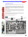
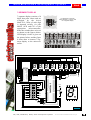
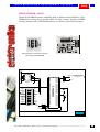
CONNECTING THE SYSTEM
The development system box contains the development system, CD and a serial
cable.
NOTE: Jumper JPP has to be in the upper position when you work with the
development system. It should be set to the lower position only when the
development system is used in certain applications when the programmer is
no longer needed.
Step no.1 The first thing to do is to take the system out of a box and to connect
the PSoC programmer to the development system, using the flat cable. Connect
one end of the parallel cable to the parallel port of the computer, and its other end
to the PSoC programmer.
Step no.2 Second step is to connect the power supply. It can be AC or DC, as
desired, and the voltage should be between 9V and 12 V. The figure below illustrates the first contact with the development system.
Step no.3 Install the PSoC prog software.
0V
ON
+
+
+
16MHz
AEC00G
ON
+
RT
VA A
CR2032
3V/230mA
32.768KHz
MCP2510
P1[1]
P1[0]
1 2 3 4 5 6 7 8
CY8C26233
CY8C26443
CY8C26643
Pot-P2
MAX232
32.768
1 2 3 4 5 6 7 8
S
ER P
LM7805
0099
B80
C1000
When JPP jumper is in
upper position microcontroler
is in PROGRAM mode
N
AI
PIH
2.5V
Connector for RS232
communication of
Konektor za RS232
microcontroller
and
komunikaciju
the computer. i racunara.
mikrokontrolera
+
+5V
Power supply
Napajanje
AC/DC 9-12V
9-12V
AC/DC
Connector for
external proKonektor za eksterni
grammer
of PSoC
programator
PSoC
microconmikrokontrolera
troller
+
When programming jumper goes
Prilikom programiranja džamper
to the
poisition
when in
je u upper
gornjem
položaju,and
a u radnom
running
it goes
to the !lower
režimumode
je u donjem
položaju
position !
Pin 1
VCC
GND
RST
GND
GND
GND
VOUTP
Figure 1.
AT24C04
PCF8583
MAX7219
LTC485
+
LCD on PORT1
PIH
LCD contrast
P[0]
P[1]
P[2]
P[3]
ATTENTION:
SW2 - enables LEDs on P3, DS1820, I2C communication
selects RS485 or RS232 communication, and
connects potentiometer to analog input P0[0]
SW3 - enables SPI communication and beeper
JP1 - connects buttons to +5V or GND when pressed
S
ER P
PIC, AVR, MC68HC11, i8051, PSoC development systems
JP1
N
AI
GND
VCC
Vee
P[5]
P[6]
P[4]
LCD on PORT3
GND
+5V
To PORT4
pins
www.mikroelektronika.co.yu
3
mikroElektronika
development
systems
PSoC
development system
DESCRIPTION OF THE DEVELOPMENT SYSTEM
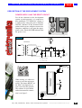
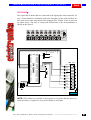
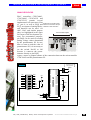
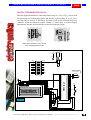
POWER SUPPLY AND THE RESET CIRCUIT
For all the elements in the development
system to work properly, it is required to
have stabilized +5V. With PSoC system, it
is achieved by using the power stabilizer
LM7805. Because of the increased dissipation which occurs at higher current consumption, stabilizer is set upon the appropriate cooler. Diode POWER indicates that
the power is on.
LM7805
0099
B80
C1000
+
+
2
TO-220
Figure 2.
LM
7805
Transformer
Transformator
1 2 3
D1
B80C1000
~
+5 V
220V
9V
~
~
-
1
+
LM7805
3
2
+
R2
+
C2
C5
C3
Power ZEL
~
C8
C2 = 470 µ F, C3 = 100nF,
C5 = 100nF, C8 = 10µ F
SP
VPOUT
Programmingpreko
with
Programiranje
ISP programatora
programmer
+5V
+5V
Reset
VCC
P0[6]
P0[4]
P0[2]
P0[0]
P2[6]
P2[4]
P2[2]
P2[0]
P3[6]
P3[4]
P3[2]
P3[0]
Xres
P4[6]
P4[4]
P4[2]
P4[0]
P5[2]
P5[0]
P1[6]
P1[4]
P1[2]
P1[0]
10ΚΩ
P0[7]
P0[5]
P0[3]
P0[1]
P2[7]
P2[5]
P2[3]
P2[1]
P3[7]
P3[5]
P3[3]
P3[1]
SMP
P4[7]
P4[5]
P4[3]
P4[1]
P5[3]
P5[1]
P1[7]
P1[5]
P1[3]
P1[1]
VSS
CY8C26643
When testing, it is often necessary to reset the microcontroller. The button RESET on
the PSoC development system is used for this purpose.
The scheme of reset button
and microcontroller connection is on figure 3.
Figure 3.
32.768 KHz
N
PI H
ER
AI
LCD contras
R2 = 330 Ω , RR1=10K Ω
+5V
PIC, AVR, MC68HC11, i8051, PSoC development systems
www.mikroelektronika.co.yu
4
mikroElektronika
development
systems
PSoC
development system
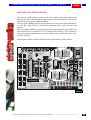
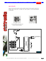
SWITCHES AND THEIR PURPOSE
The purpose of DIP switches on the system is to establish or break the connections
between the microcontroller and the development system peripherals. DIP switches divide into two groups: SW2 and SW3.
The first group, SW2, connects microcontroller I/O lines to the digital thermometer, I2C bus, serial RS-232 and RS-485 communication circuits and the mini
speaker.
The second group, SW3, conects the appropriate microcontroller pins to SPI communication bus, driver MAX7219 for 7-segment LED display, CAN communication lines and the potentiometer P2, whose voltage can be read thanks to the internal A/D converter.
The following tables symbolically display the organization of DIP switches.
PI H
ON
1 2 3 4 5 6 7 8
N
AI
+
SW 2
+
+
16MHz
AEC00G
ON
LCD on PORT1
LTC485
+
SW 3
PIH
LCD contrast
P[0]
P[1]
P[2]
P[3]
MOSI
MAX7219
MISO
CLK
SPI_SS1-MAX7219
SPI_SS3-CAN
INT-CAN
RESET-CAN
POT P2
AT24C04
PCF8583
S
ER P
JP1
N
AI
GND
VCC
Vee
P[5]
P[6]
P[4]
RT
VA A
CR2032
3V/230mA
32.768KHz
CY8C26233
P1[6]
P1[5]
P1[4]
P1[2]
P5[0]
P5[1]
P5[2]
P0[0]
LCD on PORT3
ATTENTION:
SW2 - enables LEDs on P3, DS1820, I2C communication
selects RS485 or RS232 communication, and
connects potentiometer to analog input P0[0]
SW3 - enables SPI communication and beeper
JP1 - connects buttons to +5V or GND when pressed
+
MCP2510
1 2 3 4 5 6 7 8
CY8C26443
CY8C26643
Pot-P2
MAX232
32.768
LM7805
0099
+
0V
S
ER P
When JPP jumper is in
upper position microcontroler
is in PROGRAM mode
+
+5V
2.5V
DS1820
I2C-SDA
I2C-SCL
B80
485-R/T
C1000
RS232 & 485 -TX
RS232 & 485 -RX
INT-RTC
ZVUCNIK
P2[7]
P2[1]
P2[0]
P0[1]
P0[7]
P0[6]
P2[2]
P1[7]
GND
+5V
To PORT4
pins
Figure 4.
PIC, AVR, MC68HC11, i8051, PSoC development systems
www.mikroelektronika.co.yu
5
mikroElektronika
development
systems
PSoC
development system
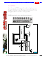
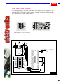
LED DIODES
The system has 8 diodes that are connected to the appropriate microcontroller via
port 3. These diodes are ordinarily used in the first phase of the work, but they are
also used for the later indications of the program flow. Diodes’ looks is given on
the figure below. The way to connect the LED diodes to the microcontroller is
shown on the figure 5.
JP1
GND
+5V
To PORT4
pins
Programming with
ISP
Programiranje
preko
ISPprogrammer
programatora
VPOUT
32.768 KHz
+5V
RN2 330Ω
+5V
P3[7]
Reset
VCC
P0[6]
P0[4]
P0[2]
P0[0]
P2[6]
P2[4]
P2[2]
P2[0]
P3[6]
P3[4]
P3[2]
P3[0]
Xres
P4[6]
P4[4]
P4[2]
P4[0]
P5[2]
P5[0]
P1[6]
P1[4]
P1[2]
P1[0]
10ΚΩ
CY8C26643
P0[7]
P0[5]
P0[3]
P0[1]
P2[7]
P2[5]
P2[3]
P2[1]
P3[7]
P3[5]
P3[3]
P3[1]
SMP
P4[7]
P4[5]
P4[3]
P4[1]
P5[3]
P5[1]
P1[7]
P1[5]
P1[3]
P1[1]
VSS
P3[6]
P3[5]
P3[4]
P3[3]
P3[2]
P3[1]
P3[0]
+5V
Figure 5.
NOTE: LED diodes are switched on by logical one. It means that the microcontroller must have a logical one on a pin for diode to emit light.
PIC, AVR, MC68HC11, i8051, PSoC development systems
www.mikroelektronika.co.yu
6
mikroElektronika
development
systems
PSoC
development system
PUSH BUTTONS
System features one RESET button and 8 buttons for simulating the system command inputs. Graphic scheme of the buttons-controller connection via port 4 is on
the figure 6. Depending on jumper JP1 setting, pressing the button will set either
logical zero or logical one on the appropriate pin. In the example shown on the following figure, buttons are connected to +5V via jumper JP1.
NOTE: Keyboard and the buttons cannot be used simultaneously !
JP1
GND
+5V
To PORT4
pins
Programming
ISP
Programiranjewith
preko
ISPprogrammer
programatora
VPOUT
+5V
+5V
Reset
32.768 KHz
VCC
P0[6]
P0[4]
P0[2]
P0[0]
P2[6]
P2[4]
P2[2]
P2[0]
P3[6]
P3[4]
P3[2]
P3[0]
Xres
P4[6]
P4[4]
P4[2]
P4[0]
P5[2]
P5[0]
P1[6]
P1[4]
P1[2]
P1[0]
10ΚΩ
CY8C26643
P0[7]
P0[5]
P0[3]
P0[1]
P2[7]
P2[5]
P2[3]
P2[1]
P3[7]
P3[5]
P3[3]
P3[1]
SMP
P4[7]
P4[5]
P4[3]
P4[1]
P5[3]
P5[1]
P1[7]
P1[5]
P1[3]
P1[1]
VSS
P4[0]
P4[1]
P4[2]
P4[3]
P4[4]
P4[5]
P4[6]
P4[7]
+5V
JP1
Figure 6.
+5V
PIC, AVR, MC68HC11, i8051, PSoC development systems
www.mikroelektronika.co.yu
7
mikroElektronika
development
systems
PSoC
development system
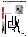
4X3 MATRIX KEYBOARD
4x3 matrix keyboard is very suitable in
occasions when 8 buttons are insufficient.
The keyboard connects to the pins of port
4 in same way as the buttons.
+
16MHz
AEC00G
ON
3
4
5
6
7
8
9
RT
VA A
CR2032
3V/230mA
32.768KHz
CY8C26233
2
MCP2510
MAX72
*
PIH
S
ER P
N
AI
0, I2C communication
mmunication, and
nalog input P0[0]
and beeper
GND when pressed
#
0
LCD contrast
1 2 3 4 5 6 7 8
NOTE: Keyboard and the buttons cannot be used simultaneously !
+
1
Programming with
ISP
Programiranje
preko
ISPprogrammer
programatora
VPOUT
+5V
+5V
Reset
32.768 KHz
VCC
P0[6]
P0[4]
P0[2]
P0[0]
P2[6]
P2[4]
P2[2]
P2[0]
P3[6]
P3[4]
P3[2]
P3[0]
Xres
P4[6]
P4[4]
P4[2]
P4[0]
P5[2]
P5[0]
P1[6]
P1[4]
P1[2]
P1[0]
10ΚΩ
CY8C26643
P0[7]
P0[5]
P0[3]
P0[1]
P2[7]
P2[5]
P2[3]
P2[1]
P3[7]
P3[5]
P3[3]
P3[1]
SMP
P4[7]
P4[5]
P4[3]
P4[1]
P5[3]
P5[1]
P1[7]
P1[5]
P1[3]
P1[1]
VSS
P4[0]
P4[1]
P4[2]
P4[3]
P4[4]
P4[5]
P4[6]
P4[7]
+5V
JP1
+5V
PIC, AVR, MC68HC11, i8051, PSoC development systems
Figure 6.
www.mikroelektronika.co.yu
8
mikroElektronika
development
systems
PSoC
development system
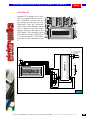
LCD DISPLAY
7 8
8C26643
Pot-P2
CY8C26233
CY8C26443
Standard LCD display (2x16 characters) is supplied. However, this is
not a limitation, because any display, having the same type of communication with the microcontroller, can be used. Display contrast
can be adjusted using the potentiometer placed to the right of the
LCD display. The following figure
shows how to connect LCD to port
1 of microcontroller CY8C26643.
LCD may be also connected to port
3.
LCD on PORT1
PI H
LCD contrast
P[0]
P[1]
P[2]
P[3]
ATTENTION:
SW2 - enables LEDs on P3, DS1820, I2C communication
selects RS485 or RS232 communication, and
connects potentiometer to analog input P0[0]
SW3 - enables SPI communication and beeper
JP1 - connects buttons to +5V or GND when pressed
S
ER P
N
AI
GND
VCC
Vee
P[5]
P[6]
P[4]
LCD on PORT3
Programmingpreko
with
Programiranje
ISPprogramatora
programmer
ISP
+5V
1
D0 D1 D2 D3 D4 D5 D6 D7
+5V
+5V
Reset
L cD
d i sp l ej
R/W
RS
E
D4
D5
D6
D7
+5V
32.768 KHz
Vss Vdd Vee RS R/W E
VCC
P0[6]
P0[4]
P0[2]
P0[0]
P2[6]
P2[4]
P2[2]
P2[0]
P3[6]
P3[4]
P3[2]
P3[0]
Xres
P4[6]
P4[4]
P4[2]
P4[0]
P5[2]
P5[0]
P1[6]
P1[4]
P1[2]
P1[0]
10ΚΩ
P0[7]
P0[5]
P0[3]
P0[1]
P2[7]
P2[5]
P2[3]
P2[1]
P3[7]
P3[5]
P3[3]
P3[1]
SMP
P4[7]
P4[5]
P4[3]
P4[1]
P5[3]
P5[1]
P1[7]
P1[5]
P1[3]
P1[1]
VSS
CY8C26643
Kontrast LCD-a
VPOUT
Figure 7.
PIC, AVR, MC68HC11, i8051, PSoC development systems
www.mikroelektronika.co.yu
9
mikroElektronika
development
systems
PSoC
development system
7-SEGMENT DISPLAY
PI H
Pot-P2
S
ER P
JP1
N
AI
LCD contrast
It is necessary
to prekidaca
have all
Neophodno
je da tri
three
and 4) ON
(1,
3 i switches
4) budu u(1,
ON3polozaju
za
for 7-segment display
sedmosegmentni
displej
ON
1 2 3 4 5 6 7 8
7-segment display consists of 8
digits that print values and are
refreshed by the driver
MAX7219. Value of each digit
is inputted serially via pins
MOSI, SCK and CS3 of the
appropriate
microcontroller,
hence the switches have to be set
as shown on the figures below.
LED display’s looks is given on
the picture below, and the figure
8 shows how to connect 7-segment display to the microcontroller.
GND
+5V
To PORT4
pins
8. 8. 8. 8. 8. 8. 8. 8.
MAX7219
DIN
DIG0
DOUT
SEGD
DIG4
GND
DIG6
DIG2
DIG3
SEGDP
SEGE
SEGC
V+
ISET
DIG7
GND
DIG5
DIG1
LOAD
SEGG
SEGB
SEGF
SEGA
CLK
P5[1]
P5[2]
P0[0]
SCK
CS3
CS4
INT-CAN
RST-CAN
POT-P2
SW3
+5V
VPOUT Programiranje
Programming preko
with
ISPprogramatora
programmer
ISP
+5V
+5V
8.
g
Reset
P5[0]
MISO
VCC
P0[6]
P0[4]
P0[2]
P0[0]
P2[6]
P2[4]
P2[2]
P2[0]
P3[6]
P3[4]
P3[2]
P3[0]
Xres
P4[6]
P4[4]
P4[2]
P4[0]
P5[2]
P5[0]
P1[6]
P1[4]
P1[2]
P1[0]
10ΚΩ
P1[2]
MOSI
P0[7]
P0[5]
P0[3]
P0[1]
P2[7]
P2[5]
P2[3]
P2[1]
P3[7]
P3[5]
P3[3]
P3[1]
SMP
P4[7]
P4[5]
P4[3]
P4[1]
P5[3]
P5[1]
P1[7]
P1[5]
P1[3]
P1[1]
VSS
CY8C26643
P1[4]
ON
P1[5]
SCK
1 2 3 4 5 6 7 8
P1[6]
+5V
10ΚΩ
f
K
a
b
a
f
b
g
e
c
d
e
d
dp
K
c
dp
32.768 KHz
Figure 8.
PIC, AVR, MC68HC11, i8051, PSoC development systems
www.mikroelektronika.co.yu
10
mikroElektronika
development
systems
PSoC
development system
ANALOG BLOCKS
Pot-P2
When JPP jumper is
upper position micr
is in PROGRAM mod
2.5V
0V
S
ER P
N
AI
PIH
+5V
ON
1 2 3 4 5 6 7 8
PSoC controllers CY8C26643,
CY8C26443, CY8C26233 and
CY8C25122 contain several
implemented A/D converters. Pins
POT-P2 is ON if potenof port 0, as well as P2[6] and Switch
Prekidaè
položaju
tiometer
P2POT-P2
is used je
foruthe
preON
ako seofpotenciometar
P2 koristi
sentation
A/D
conversion
P2[7] are outputs of analog blocks, za prezentaciju A/D konverzije
and therefore can be used for
ADC, DAC and similar purpose
A/D converter
inputs
Ulazi
A/D konvertora
(they are highlighted in the upper
left corner of the development system). For presentation purposes,
pin P0[0] can be used for reading
analog voltage values determined
by the potentiometer P2. In case
that we want to read the value of
potentiometer P2, it is necessary to
set the switch Pot-P2 to ON
because it connects the potentiometer directly to pin P0[0].
Figure 9 shows a graphic scheme of the connection between the microcontroller
CY8C26643 and the potentiometer P2.
Figure 9.
Programming preko
with
Programiranje
ISPprogramatora
programmer
ISP
VPOUT
P1[2]
P5[0]
P5[1]
P0[0]
+5V
MISO
SCK
CS3
P2
CS4
INT-CAN
RST-CAN
POT-P2
SW3
+5V
VCC
P0[6]
P0[4]
P0[2]
P0[0]
P2[6]
P2[4]
P2[2]
P2[0]
P3[6]
P3[4]
P3[2]
P3[0]
Xres
P4[6]
P4[4]
P4[2]
P4[0]
P5[2]
P5[0]
P1[6]
P1[4]
P1[2]
P1[0]
+5V
+5V
10ΚΩ
Reset
P5[2]
MOSI
CY8C26643
P1[4]
ON
P1[5]
1 2 3 4 5 6 7 8
P1[6]
P0[7]
P0[5]
P0[3]
P0[1]
P2[7]
P2[5]
P2[3]
P2[1]
P3[7]
P3[5]
P3[3]
P3[1]
SMP
P4[7]
P4[5]
P4[3]
P4[1]
P5[3]
P5[1]
P1[7]
P1[5]
P1[3]
P1[1]
VSS
32.768 KHz
PIC, AVR, MC68HC11, i8051, PSoC development systems
www.mikroelektronika.co.yu
11
mikroElektronika
development
systems
PSoC
development system
MINI SPEAKER
Figure 10 shows the switch’s position and the location for the speaker, and the following figure shos how to connect the mini speaker to the microcontroller
CY8C26643.
ON
1 2 3 4 5 6 7 8
LTC485
+
Neophodno je da prekidac
The switch Beeper (8) SW2 has to be
Beeper
(8) SW2 bude u ON polozaju
ON when using mini speakers
pri koriscenju mini zvucnika
+
100Ω
10ΚΩ
P0[1]
P0[7]
P2[2]
P1[7]
SCL
R/T
TX
RX
INT-RTC
BEEPER
SW2
+5V
32.768 KHz
PIC, AVR, MC68HC11, i8051, PSoC development systems
VPOUT Programiranje
Programming preko
with
ISPprogramatora
programmer
ISP
+5V
+5V
Reset
P0[6]
DQ
SDA
VCC
P0[6]
P0[4]
P0[2]
P0[0]
P2[6]
P2[4]
P2[2]
P2[0]
P3[6]
P3[4]
P3[2]
P3[0]
Xres
P4[6]
P4[4]
P4[2]
P4[0]
P5[2]
P5[0]
P1[6]
P1[4]
P1[2]
P1[0]
10ΚΩ
P2[0]
ON
P2[1]
1 2 3 4 5 6 7 8
P2[7]
CY8C26643
P0[7]
P0[5]
P0[3]
P0[1]
P2[7]
P2[5]
P2[3]
P2[1]
P3[7]
P3[5]
P3[3]
P3[1]
SMP
P4[7]
P4[5]
P4[3]
P4[1]
P5[3]
P5[1]
P1[7]
P1[5]
P1[3]
P1[1]
VSS
Figure 10.
www.mikroelektronika.co.yu
12
mikroElektronika
development
systems
PSoC
development system
REAL TIME CLOCK - PCF8583
The system features a real time clock (RTC) with battery power supply. The serial model RTC PCF8583 by Philips is used. Graphic scheme of microcontrollerRTC connection is shown on the figure 11.
X232
+
ON
RT
VA A
MCP2510
CR2032
3V/230mA
32.768KHz
1 2 3 4 5 6 7 8
16MHz
AEC00G
+
AT24C04
PCF8583
Potrebno je da prekidaci
2,3
i 7 switches
svica SW2
polozaju
SW2
2, budu
3 andu7ON
have
to be
pri koriscenju
ON whenRTC
usingcasovnika
RTC
+5V
32,768KHz
OSCI
OSCO
A0
GND
10ΚΩ
5-25pF
BAT43
Vdd
INT
SCL
SDA
PCF8583
100nF
BAT43
56
VPOUT
3V/230mA
P0[7]
P0[6]
P2[2]
P1[7]
SDA
SCL
R/T
TX
RX
INT-RTC
BEEPER
SW2
+5V
Programming preko
with
Programiranje
ISPprogramatora
programmer
ISP
+5V
+5V
Reset
P0[1]
DQ
VCC
P0[6]
P0[4]
P0[2]
P0[0]
P2[6]
P2[4]
P2[2]
P2[0]
P3[6]
P3[4]
P3[2]
P3[0]
Xres
P4[6]
P4[4]
P4[2]
P4[0]
P5[2]
P5[0]
P1[6]
P1[4]
P1[2]
P1[0]
10ΚΩ
P2[0]
ON
P2[1]
1 2 3 4 5 6 7 8
P2[7]
CY8C26643
P0[7]
P0[5]
P0[3]
P0[1]
P2[7]
P2[5]
P2[3]
P2[1]
P3[7]
P3[5]
P3[3]
P3[1]
SMP
P4[7]
P4[5]
P4[3]
P4[1]
P5[3]
P5[1]
P1[7]
P1[5]
P1[3]
P1[1]
VSS
32.768 KHz
Figure 11.
PIC, AVR, MC68HC11, i8051, PSoC development systems
www.mikroelektronika.co.yu
13
mikroElektronika
development
systems
PSoC
development system
SERIAL EEPROM - 24CXX
Beside the EEPROM memory standardly built in modern microcontrollers, serial
EEPROM for storing data is usually added for safety reasons. Positions of SW2
switches and the looks of EEPROM memory are shown on the following figure.
ON
1 2 3 4 5 6 7 8
32.768KHz
AT24C04
PCF8583
Neophodno je da prekidaci
SW2
2 and
be ON
2 i 3switches
svica SW2
budu3 uhave
ON to
polozaju
pri when
koriscenju
EEPROM-a
usingserijsko
serial EEPROM
+5V
1
2
3
4
A0
A1
NC
GND
Vcc
WP
SCL
SDA
8
VPOUT
7
6
5
24C04
P0[7]
P0[6]
P2[2]
P1[7]
SDA
SCL
R/T
TX
RX
INT-RTC
BEEPER
SW2
+5V
Programming preko
with
Programiranje
ISPprogramatora
programmer
ISP
+5V
+5V
Reset
P0[1]
DQ
VCC
P0[6]
P0[4]
P0[2]
P0[0]
P2[6]
P2[4]
P2[2]
P2[0]
P3[6]
P3[4]
P3[2]
P3[0]
Xres
P4[6]
P4[4]
P4[2]
P4[0]
P5[2]
P5[0]
P1[6]
P1[4]
P1[2]
P1[0]
10ΚΩ
P2[0]
ON
P2[1]
1 2 3 4 5 6 7 8
P2[7]
CY8C26643
P0[7]
P0[5]
P0[3]
P0[1]
P2[7]
P2[5]
P2[3]
P2[1]
P3[7]
P3[5]
P3[3]
P3[1]
SMP
P4[7]
P4[5]
P4[3]
P4[1]
P5[3]
P5[1]
P1[7]
P1[5]
P1[3]
P1[1]
VSS
32.768 KHz
Figure 12.
PIC, AVR, MC68HC11, i8051, PSoC development systems
www.mikroelektronika.co.yu
14
mikroElektronika
development
systems
PSoC
development system
DIGITAL THERMOMETER DS1820
DS1820 digital thermometer, with temperature range of -55 to 125 C, can be used
for measuring enviroment temperature and also for experimenting. It is very accurate and easy to connect. It should be set in the 3-pin socket, beneath the power
connector of the development system. Picture 13. shows how to connect digital
thermometer and the microcontroller on the development system.
ON
1 2 3 4 5 6 7 8
+
MAX232
+
+
+
Potrebno je da prekidac DS1820
SW2
switch
DS1820
has polozaju
to be ON
svica
SW2
(1)
budu(1)
u ON
when
using
digital
thermometer
pri koriscenju digitalnog termometra
+125
O
C
P2[0]
P0[1]
P0[7]
P0[6]
P2[2]
P1[7]
DS1820
SDA
4,7ΚΩ
ON
1 2 3 4 5 6 7 8
P2[1]
+5V
Vdd
DQ
GND
-55
P2[7]
DS1820
SCL
R/T
TX
RX
INT-RTC
Programming preko
with
Programiranje
programmer
ISP programatora
BEEPER
VPOUT
+5V
1
Vss Vdd Vee RS R/W E
D0 D1 D2 D3 D4 D5 D6 D7
c
+5V
PIC, AVR, MC68HC11, i8051, PSoC development systems
+5V
32.768 KHz
Figure 13.
+5V
Reset
T empe rat ura
23 . 5 stepen i
R/W
RS
E
D4
D5
D6
D7
VCC
P0[6]
P0[4]
P0[2]
P0[0]
P2[6]
P2[4]
P2[2]
P2[0]
P3[6]
P3[4]
P3[2]
P3[0]
Xres
P4[6]
P4[4]
P4[2]
P4[0]
P5[2]
P5[0]
P1[6]
P1[4]
P1[2]
P1[0]
10ΚΩ
P0[7]
P0[5]
P0[3]
P0[1]
P2[7]
P2[5]
P2[3]
P2[1]
P3[7]
P3[5]
P3[3]
P3[1]
SMP
P4[7]
P4[5]
P4[3]
P4[1]
P5[3]
P5[1]
P1[7]
P1[5]
P1[3]
P1[1]
VSS
CY8C26643
Kontrast LCD-a
SW2
www.mikroelektronika.co.yu
15
mikroElektronika
development
systems
PSoC
development system
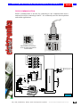
RS232 COMMUNICATION
RS232 communication is devised for connecting to one communication device,
and can be used for connecting to the PC. It is commonly used for data acquisition
and similar applications.
ON
1 2 3 4 5 6 7 8
+
P2[0]
P0[1]
P0[7]
P0[6]
P2[2]
P1[7]
+
ON
P2[1]
1 2 3 4 5 6 7 8
P2[7]
+
MAX232
+
Potrebno
je da 5
prekidaci
5i6
SW2
switches
and 6 have
SW2when
budu u
ON polozaju
tosvica
be ON
using
RS232
pri RS232 komunikaciji
communication
DQ
SDA
SCL
R/T
TX
RX
INT-RTC
BEEPER
VPOUT
SW2
4.7µ F
4.7µF
+
C1+
Vcc
V+
GND
C1- T1out
R1in
C2+
C2- R1out
T1in
VT2out T2in
R2in R2out
MAX232
+
1
6
2
7
3
8
4
9
5
prima
podatke
(Rx)
receives
data (Rx)
šalje
podatke
(Tx)
sends
data (Tx)
+5V
Programmingpreko
with
Programiranje
ISP programatora
programmer
ISP
+5V
+5V
Reset
serijski
kabl
serial cable
(1(1na
on1)1)
VCC
P0[6]
P0[4]
P0[2]
P0[0]
P2[6]
P2[4]
P2[2]
P2[0]
P3[6]
P3[4]
P3[2]
P3[0]
Xres
P4[6]
P4[4]
P4[2]
P4[0]
P5[2]
P5[0]
P1[6]
P1[4]
P1[2]
P1[0]
10ΚΩ
1
6
2
7
3
8
4
9
5
+
+5V
CY8C26643
SUB-D
connector
9-pin
SUB-D
konektor
9 pinski
4.7µ F
+
4.7µ F
P0[7]
P0[5]
P0[3]
P0[1]
P2[7]
P2[5]
P2[3]
P2[1]
P3[7]
P3[5]
P3[3]
P3[1]
SMP
P4[7]
P4[5]
P4[3]
P4[1]
P5[3]
P5[1]
P1[7]
P1[5]
P1[3]
P1[1]
VSS
32.768 KHz
Figure 14.
PIC, AVR, MC68HC11, i8051, PSoC development systems
www.mikroelektronika.co.yu
16
mikroElektronika
development
systems
PSoC
development system
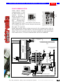
RS485 COMMUNICATION
ON
1 2 3 4 5 6 7 8
Unlike RS232, RS485
communication is used
for data transfer between
multiple devices. It
allows one participant in
communication to send
and the other to receive
data
simultaneously.
+
Potrebno je da prekidaci 5 i 6
When their transfer is fin- SW2
svica SW2
budu 5u and
ON polozaju
switches
6 have to be
RS485
ished, another two users pri
ONkoriscenju
when using
485komunikacije
communication
can exchange their data.
The figure 47 represents
RS485 input and the jumper settings necessary for the communication, while the
figure 48 shows how to connect the PC to the microcontroller on the development
system. Take care to properly connect the inputs A and B to the appropriate inputs
of the master device, or else the communication will not be established.
AT24C04
A
B
RS
485
LTC485
VPOUT
Figure 15.
Programiranjewith
preko
Programming
ISP
ISPprogrammer
programatora
+5V
Connecting the PC and the PIC microcontroller via RS485 communication
Povezivanje PCline
raèunara i PIC
mikrokontrolera preko RS485
komunikacione linije
+5V
RS485
canliniju
support
Na line
RS485
možeup
se
to 32 devices
prikljuèiti
maksimalno 32
ureðaja
+5V
P0[1]
P0[6]
P2[2]
R/T
RX
BEEPER
4.7µF
4.7µF
4.7µF
C1+
V+
Vcc
GND
+
C1C2+
C2-
T1out
R1in
R1out
T1in
T2in
R2out
VT2out
R2in
Vcc
B
A
GND
LTC485
INT-RTC
+
4.7µF
RX
TX
RTS
GND
RE
DE
DI
TX
+
P1[7]
SCL
R0
Shield, less
than
Oklopljena
parica
300m
long
dužine
manje
od 300m
P0[7]
DQ
SDA
R0
RE
DE
DI
+5V
Vcc
B
A
GND
LTC485
620Ω
P2[0]
+5V
620Ω
P2[1]
ON
P2[7]
10ΚΩ
SW2
1 2 3 4 5 6 7 8
Reset
32.768 KHz
VCC
P0[6]
P0[4]
P0[2]
P0[0]
P2[6]
P2[4]
P2[2]
P2[0]
P3[6]
P3[4]
P3[2]
P3[0]
Xres
P4[6]
P4[4]
P4[2]
P4[0]
P5[2]
P5[0]
P1[6]
P1[4]
P1[2]
P1[0]
10ΚΩ
+5V
CY8C26643
P0[7]
P0[5]
P0[3]
P0[1]
P2[7]
P2[5]
P2[3]
P2[1]
P3[7]
P3[5]
P3[3]
P3[1]
SMP
P4[7]
P4[5]
P4[3]
P4[1]
P5[3]
P5[1]
P1[7]
P1[5]
P1[3]
P1[1]
VSS
MAX232
+
RS232 toRS232
RS485
Konvertor
na converter
RS485
PIC, AVR, MC68HC11, i8051, PSoC development systems
www.mikroelektronika.co.yu
17
mikroElektronika
development
systems
PSoC
development system
CAN CONTROLLER - MCP2510
This type of communication was initially intended for the auto industry, but it has
proven so well that it soon found other industrial applications. It involves multiple
participants like RS485 communication. Components for CAN communication are
manufactured by many companies. Here we used models PCA80C250 by Philips
and MCP2510 by Microchip. When using the CAN controller, SW3 switches
have to be set as shown on the following pictures.
ON
1 2 3 4 5 6 7 8
SW3 switches 5, 6 and 7
Neophodno je da tri prekidaèa
to be
ON
when
using
(5,have
6 i 7) svièa
SW3
budu
u ON položaju
pri korišæenu CAN komunikcije
the CAN communication
Pot-P2
+
+
+
16MHz
AEC00G
H
+
L
CAN
AT24C04
32.768KHz
MCP2510
RT
VA A
CR2032
3V/230mA
PCF8583
100ΚΩ
+5V
TX-CAN Vdd
RX-CAN RST
CS
CLKOUT
TX0RTS
P1[6]
P1[5]
P1[4]
MCP2510
P1[2]
P5[1]
10Ω
+5V
TX-CAN
RS
GND
CANH
VCC
CANL
RXD
Vref
P0[0]
MISO
SCK
CS3
CS4
INT-CAN
RST-CAN
POT-P2
SW3
PCA82C250
+5V
+5V
+5V
Reset
P5[2]
MOSI
VCC
P0[6]
P0[4]
P0[2]
P0[0]
P2[6]
P2[4]
P2[2]
P2[0]
P3[6]
P3[4]
P3[2]
P3[0]
Xres
P4[6]
P4[4]
P4[2]
P4[0]
P5[2]
P5[0]
P1[6]
P1[4]
P1[2]
P1[0]
10ΚΩ
P5[0]
P0[7]
P0[5]
P0[3]
P0[1]
P2[7]
P2[5]
P2[3]
P2[1]
P3[7]
P3[5]
P3[3]
P3[1]
SMP
P4[7]
P4[5]
P4[3]
P4[1]
P5[3]
P5[1]
P1[7]
P1[5]
P1[3]
P1[1]
VSS
CY8C26643
RX1BF
ON
Vss
VPOUT
1 2 3 4 5 6 7 8
SO
SI
SCK
TX1RTS
TX2RTS
OSC2
INT
OSC1 RX0BF
16MHz
Programmingpreko
with
Programiranje
ISPprogramatora
programmer
ISP
10ΚΩ
100ΚΩ
100ΚΩ
+5V
32.768 KHz
Oklopljena
parica
Shield,
less than
300m
long od 300m
dužine manje
PIC, AVR, MC68HC11, i8051, PSoC development systems
Figure 16.
www.mikroelektronika.co.yu
18
mikroElektronika
development
systems
PSoC
development system
DIRECT PORT ACCESS
All microcontroller pins can be used as either input or
ouput.
Port pins can be accessed directly from the left side of
the development system using the flat cable. In this
way, values from external elements can be transferred
via pins of appropriate ports.
PIC, AVR, MC68HC11, i8051, PSoC development systems
www.mikroelektronika.co.yu
19