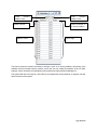
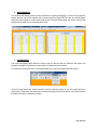
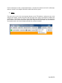
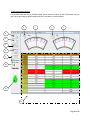
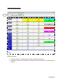
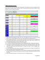
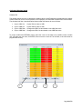
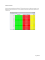
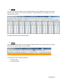
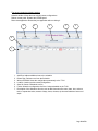
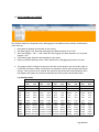
1
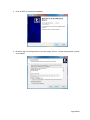
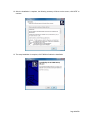
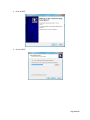
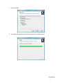
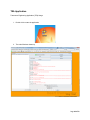
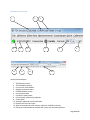
A message from the team at Heart Transverter S.A. Thanks for your recent purchase of the HT2000 Power inverter in combination with the HTREM Remote Panel. Heart Transverter S.A. takes great pride in manufacturing high quality products specially design to meet the demand of today’s busy world. You have taken the first step for achieving a better world, and saving energy; the HT2000 and the HTREM will allow you to manage the energy demand in your house or small appliances, by providing safe connection, UPS support, power factor correction and grid energy injection. If you have any questions about the HT2000 Power Module or HTREM Panel, please contact Heart Transverter at 011-506-2293-3468 (direct). For technical support and additional information about Heart Transverter S.A. products, visit our Web site at www.transverter.com or e-mail us at [email protected] Page 1 of 52 Contents IMPORTANT SAFETY INSTRUCTIONS ............................................................................................... 3 General Overview ..................................................................................................................................... 4 Software description ................................................................................................................................ 5 HT 2000 Engineering tool (TEA) ........................................................................................................ 5 Transverter Applications...................................................................................................................... 5 Software downloading instructions ........................................................................................................ 6 HT-2000 Main Engineering application ................................................................................................. 7 Installation Instructions ........................................................................................................................ 7 Heart Transverter Applications ............................................................................................................. 13 Installation Instructions ...................................................................................................................... 13 TEA Application ...................................................................................................................................... 18 Description of the tool bar ................................................................................................................. 19 Menu details explanation .................................................................................................................. 22 1. FILE MENU ............................................................................................................................. 22 2. WINDOWS .............................................................................................................................. 30 3. XILINX RAM ........................................................................................................................... 31 4. MEASUREMENTS................................................................................................................. 34 5. SCOPE/GRAPH ..................................................................................................................... 34 6. QUICK ..................................................................................................................................... 36 7. CALIBRATION ....................................................................................................................... 43 8. 9 XILINX .................................................................................................................................. 47 9. CHARTS .................................................................................................................................. 47 10. UTILITIES ............................................................................................................................ 50 11. DATA LOGGING and LOG RATE .................................................................................. 52 Annex........................................................................................................... Error! Bookmark not defined. Page 2 of 52 IMPORTANT SAFETY INSTRUCTIONS Save these instructions – This manual contains important instructions for Models HT-2000 and HT-2000T that shall be followed during operation and maintenance of the HT2000 and HT-2000T models. The manual includes instructions to modify the configuration of a HT-2000 using the engineering tool. Changing the configuration to improper values can render the unit unserviceable. DO NOT attempt to make changes without consulting the engineering department of Heart Transverter S.A. Read all of the instructions and cautions in the manual before operating the HT2000. • • • • • • • • This guide includes safety operational instructions for the HT2000 Transverter. The following safety symbol conventions are used throughout this guide to indicate potentially dangerous conditions and/or important safety instructions. Please be advised that for all Transverter installations, qualified personnel are required. Do not attempt to perform this installation on your own. TheHT2000 produces voltages and currents capable of causing severe injury or even death. Caution must be taken when installing and operating the HT2000. Ensure that all power (both AC and DC) have been disconnected BEFORE installing, servicing, or removing theHT2000Transverter. Do not install the HT-2000 on, near or over combustible surfaces. Do not install the HT-2000 on a confined space where there is presence of combustible fumes! Always follow the proper electrical code regulations during installation for proper wiring (i.e. ANSI/NFPA 70 for United States or CEC for Canada) Symbols Precaution! Watch! Take notice! High voltage risk High temperature Page 3 of 52 General Overview The HT2000 power module is a Universal Power Interface that, by using intense amounts of logic, can bi-directionally transfer power between any combinations of its four connections. Each power module has two DC connections and two AC connections. Each DC terminal can connect to anything from 10-50 volts to things like batteries of any chemistry, solar panels, fuel cells, DC wind generators, alternators, etc. The AC connections are for AC loads, the Grid and generators. The HT-2000 power module requires the HTREM to be operated, with the control panel in place, it’s very easy to operate the unit, and the user can read the power consumption, battery status and also, send information to a personal computer for further analysis. Additionally, in order to proper configure the unit, its required the use of a software engineering tool, this software allows the user to change and create custom software configurations for the unit. This user manual includes the descriptions that can be found on the TEA Software when the mouse is pointed directly over each option on the menu, the software itself has self help, when the user is in doubt, the mouse can be place over that option an a brief description will appear. Page 4 of 52 Software description The Transverter program package, is a set of programs that enable the user to control de HT-2000 unit in unique ways, these programs allow the user to change settings and create custom configuration files according to their needs. The software package includes 2 main compressed files, the first one is HT 2000 Engineering tool (TEA) This software enables the user to change and modified several features within the HT2000 power module, here the user have the following options: 1. 2. 3. 4. Check the Xilinx Ram cells Oscilloscope function for each power module Data log Registry modification Transverter Applications The Transverter applications are a series of software programs coded in C, that allow the user to read data from the power module, the user, can modify some features of the HT2000 power module in a more faster way. Also, within this package the user can: 1. Safe configuration files 2. Restore configuration files from the HT2000 Power module 3. Verify and read voltaje, current values from the Power Module The programs currently runs under Java Code on computers with the following operative systems: Windows Vista Windows 7 Windows 8.1 Windows Server 2008 General System Requirements Intel Microprocessor (high speed is recommended, above 1.5 GHz) 1 Gb Ram memory or more. 1 Gb free space on hard drive 1 USB 2.0 Port In order to run the software, the latest version of Java is required on the host computer, to download Java, browse into the Java website and download the latest version: www.java.com/en Page 5 of 52 Software downloading instructions To get the software, it is necessary to log into the Heart Transverter web site and click on When SUPPORT is accesed, the next screens shows. Browse through the page and download the following programs: 1. Setup_HT2000_12-10-14-01.Eexe 2. Setup_transverter_apps_0.7.exe Important!!!! Prior to install the Transverter software, first connect the HTREM Module with a USB cable to the computer. Page 6 of 52 HT-2000 Main Engineering application Installation Instructions 1. Double click on: SETUP_HT2000_12-10-14-01.exe 2. Click on RUN Page 7 of 52 3. Click on NEXT to continue the installation 4. Read the user License Agreement, if the user agress, click on “I accept the agreement” and the click on NEXT. Page 8 of 52 5. Input all the necesary information on this window, the serial number is just for informacional purposes, the user can input here the HT Serial number (located on a sticker, on the outside of the unit) 6. Input the installation directory, to avoid conflicts, set it to C:\AVR, then click on NEXT Page 9 of 52 7. Select what ever if the user want a Star Menu Folder, in this instruction, the folders name are created, click on NEXT to continue. 8. Select if the users want to create Desktop Icons and/or quick launch icons Page 10 of 52 9. This window is the summary of the installation, here the user can verify all the setup information prior to install the software, click NEXT to continue. 10. Click INSTALL to begin installation of all the files into the computer. 11. The software will began the installation Page 11 of 52 12. After the installation is complete, the following summary will show on the screen, click NEXT to continue. 13. The setup installation is complete, click FINISH to finalize the installation Page 12 of 52 Heart Transverter Applications Installation Instructions 1. Double click on: Setup_transverter_apps_0.7.exe 2. Click on RUN: Page 13 of 52 3. Click on NEXT 4. Click on NEXT: Page 14 of 52 5. Click on NEXT: 6. Click on NEXT: Page 15 of 52 7. Click on INSTALL: 8. The software will install and a progress bar will show the installation status: Page 16 of 52 9. Click on FINISH to complete the installation and exit the setup program: Page 17 of 52 TEA Application Transverter Engineering Application (TEA) Usage 1. Double chick to start the application 2. The main Windows shows up Page 18 of 52 Description of the tool bar 1 2 4 10 5 6 11 3 7 12 8 9 13 General item description 1. 2. 3. 4. 5. 6. 7. 8. 9. 10. 11. 12. 13. TEA Software Version TEA Installation directory Current user of the software Software connection status HTREM Software versión Current system date Connection quality status Current power module beign analyzed Control panel Automatic update for the Xilinx Windows Refresh rate for the XU option When checked the xilinx ram memory cannot be modified by the user Quietly and automatically the software will correct any connection problems Page 19 of 52 The software includes a tool bar with several options and selections The tool bar selections are the following: 1. File This menu includes general features like FLASH transfer to and from the unit, calibration restoration, USB test, and HTREM flash update. 2. Windows Displays the active windows on the program, control window, and stats window can be accesed here. 3. Xilinx Ram This feature access the Xilinx Ram Block 2, in here the user can input an address of memory and directly program a feature on the HT-2000, for the address and codes, it’s necessary to read the support documentation TRDATA.DOC 4. Measurements This menu shows, the control words or measurement words for both cards withing the power module (THIGH and TLOW) 5. Scope/Graph This menu can access the oscilloscope feature of the power module, it allows the program to display up to 4 AC Oscilloscopes, and also, can display 1 DC oscilloscope for the unit. 6. Quick This menu can access the numerical data for both TLOW and THIGH cards, it will display general information with regard to power, current and voltage, in this menu, the power can be regulated, also, the charching capabilities can be modified here. 7. Calibration This menu allows the calibration of the power module and the T13X current lines. 8. 9 Xilinx This menu allows the user to access the different RAM registers from the Xilinx chip, the changes that can be plased here can affect the unit severely, for reference, check documentation TRDATA.DOC 9. Charts This menu will display power graphs and efficiency charts for data analysis. Page 20 of 52 10. Utilities Allows the user to edit a scheduled on the EPROM of the power module, also, it enables the user to reset the TEA software application to clean remnant errors from the application itself. 11. Data Log Enables the user to start a data log of the unit, when enable, the unit will start getting telemetry data, this data can be later analyzed on a special Excel spreadsheet. 12. Logging Rate Allows the user to select different times and rates for getting the data out of the power module, all the data collected from the data logging, will be store on a flash memory inside the HT2000, it’s important to clarify, that this memory has a total capacity of 2 MB, when the memory gets full, the system will rewrite the information from the beginning, erasing old data that is not retrieved. Page 21 of 52 Menu details explanation 1. FILE MENU 1.1 Flash • Save Xilinx Code to file: Allows the user to save a copy of the Xilinx code to a file in the *.MCS format, this file can be used to restore the Xilinx rem Code • Restore Xilinx Code from file: Transfers the *.MCS file to the REM flash memory, the next time you cycle power on the REM, it will load and run the new xilinx code. • Erase FLASH sector: The user is prompted to erase a sector in the REM FLASH. Each sector is 0x10000 bytes long, this is where the data log data is stored. • Read REM FLASH: The user can select an address from 0 to 0x1FFFFFF and specify the number of bytes to read, a máximum of 0xF0 bytes can be displayed. Page 22 of 52 1.2 Xilinx Config • Save HT2000 configuration to file: Saves the control setting to a file, such as min/max voltajes and currents. If the users specifies a *.CSV file extensión, then the calibration constants are also saved. • Restore HT2000 configuration from a file: Restores the control settings from a file saved using he “save HT2000 configuration to file”, the calibration constants are not restored. • Compare HT2000 configuration files: Compares 2 files saved using the “Save HT2000 configuration to file”, use this to see what control values are different between configurations. • Save HT2000 configuration permanently: Allows the user to ensure that the configuration is restored after a REM power cycle, this option can be used adter “Restore Xilinx code from file” command. Page 23 of 52 1.3 Restore PM Calibration Constants The user can select a Xilinx configuration file and write the calibration constanst to the remote panel, the Xilinx configuration files are in the CFG directory and use the *.CSV extensión. 1.4 Read range external EEPROM Enables the user to display REM EEPRON contents, the user can specify an address from 0 to ox7FFF, and specify up to 0xFF bytes to display. Page 24 of 52 1.5 USB Test Enables the user to test the USB Communications, this can be used when the user is experimenting issues with the USB port. 1.6 Listen for client sockets This menu is experimental, and up to date it has not been debugged. Page 25 of 52 1.7 Connect to server in passive mode This option enables the user to get data from a REM running on a different computer, this option is experimental and it not fully debugged (normal user should not use this option) 1.8 Save Desktop Allows the user to save the open windows locations and settings to the PREFS.XML file Page 26 of 52 1.9 USB View Shows USB information concerning remote panels connected to the PC, allows the user to select which remote panel to communicate with 1.10 Update REM CODE Enables the user to burn new code into the remote panel, the user is prompted to download a hex file or to select one from the bootloader/bin directory, the file must be in the bootloader/bin directory. Page 27 of 52 1.11 Update this application Install a new versión of the Transverter enginnering application, the user is prompted to download a TEA SETUP file or select one from the local hard drive. 1.12 Clear runtime and error count Resets the display info located on the upper right hand corner of the window, this is mostrly USB related information for debuggind purposes. Page 28 of 52 1.13 Log Off Will display the Log On Display, this enables to user to log into the application as a new user, the default log is GUEST, and has no password. 1.14 EXIT This closes the application, the short cut method can be CTRL+X or CTRL+F4 Page 29 of 52 2. WINDOWS Allows the user to activate the Control Window (Ctrl+K), Stats windows, or settings window, the active windows will appear on grey color below. 2.1 Control This window display status information and allows various control functions. 2 1 3 4 5 6 7 13 12 8 9 10 11 1. USB data sent to the HTREM panel (done using ítem 10 and 11). Page 30 of 52 2. 3. 4. 5. 6. 7. 8. 9. Connection status (Green = connected, Gray = No connection), HTREM Version, Date Stats: Opens software statistics (for debugging purposes). Save Logs: The user can safe a log in a form of a *.TXT file. Disconnect: Disconnects the HTREM panel from the PC. Settings: Opens the software settings, this is for debugging purposes and its experimental. Clear Log: Cleans all the messages that are show non screen 13. No USB: Disables the USB connection to the HTREM. Custom: Has a series of predefined commands to send to the HTREM for response, the status will appear on Item 1. 10. Blank space (total 8): These are used to send USB instructions to the HTREM. 11. Send: Sends the command to the HTREM. 12. General Systems information: This sections displays in the following order, general information about the system, like, HTREM System time, HTREM Version, TLOW Xilinx versión and THIGH Xilinx version. 3. XILINX RAM This menu its used to display and modify the memory locations on the REM panel, use with caution, because a bad input in the memory fields can alter the functionability of the device. To access the memory menu, click on NEW. Page 31 of 52 Initial memory address value Address column Address values Final memory address value Value contained on a memory address Value range The picture shows the interface necessary to change a value on a memory address, this section of the software must be used with extreme caution, in here, the user can modify the operation of the HT-2000, improper values can alter the functionability of the system and create permanent damage to it. The system itself has a security key, when this key is programmed, the programmer or engineer can alter all the functions of the system. Page 32 of 52 To unlock the system follow the sequence: 1. Highlight the initial memory value and input “400” 2. Highligth the final memory address value and input “40F” This value can be B42C to unlock the system The system will update the memory address and the values, on the address 040F click on the value and input the following unlocking key: B42C, then hit ENTER. The panel is now unlock, this state can be seen on the HTREM panel as a blinking of all 4 leds, this indicates that all the memory positions can be changed and modified, when the system is rebooted, the system will lock automatically. This feature should be used only for advance troubleshooting and engineering research, consult the appendix for additional memory changes and features. Page 33 of 52 4. MEASUREMENTS This windows will display general memory information for system debugging, it’s used as a programmer feature, the user can see the contents of the memory blocks for Thigh and Tlow, also, the window display information with regards to control words used for the TLow and Thigh boards, the screen looks like this and has a drop down menu for selecting both cards. 5. SCOPE/GRAPH The scope and graph feature allows the users to get AC data and also DC data from the system, the program can graph 4 simultaneous oscilloscopes for 4 different power modules. To access the oscilloscope click on the Scope/Graph menu and click the desired power module. All the AC scope menus are exactly the same, however, when the system is new, the scope need to be configured for each wave, this values can be change according to the user selection, the screen looks like this when the system is operating normally: Page 34 of 52 1 2 3 10 11 4 12 13 5 6 7 8 9 Windows description 1. 2. 3. 4. 5. 6. 7. 8. 9. 10. 11. 12. 13. Open a previous saved oscilloscope image Save an oscilloscope screen shot Pause the wave output Wave output selection screen Channel description Location of the wave output on the vertical plane Wavescale Color selection for each wave Shows Hex or RMS values on the waveshapes Change the phase angles of the wave Set the scale for the period Increases or decreases the amount of wave links on the graph On this window the waveshapes are displayed. The values that need to be programmed in each item are: Channel 0 1 2 3 Offset 110 -49 66 -103 Scale 0.04 0.15 0.15 0.04 Name V out I in I out Vin Page 35 of 52 The DC oscilloscope it’s still an experimental feature, it includes all the features of the AC oscilloscope, however, is better to use a digital multimeter to obtain data from the system 6. QUICK The quick menu its one of the most important features on the TEA software, it allows the user to fully configure the voltages, currents and power output and input of the system, the software is limited to the modifications, in this manner, the system cannot get damage from changing the values. The quick menu has 3 windows, one for each board on the system,Tlow, Thigh and the T13X module, the last windows is for presenting values, the numerical data presented here cannot be modified. Page 36 of 52 TLOW Configuration Window The windows allows the user to modified voltage, power and current values on the TLOW board, also, the user can set the charging and discharging values for the battery, and solar panels. 1 2 3 4 5 6 7 8 9 10 11 12 Page 37 of 52 Windows description 1. 2. 3. 4. 5. 6. 7. 8. 9. 10. 11. 12. Changes the values of the graphic, both spaces are to define the voltaje range of the graphic. The voltage in a graphical meter display. Changes the value of the graphic, both spaces is to define the current range of the graphic. The current in a graphical meter display. Selection of the power module to be analyzed Selection of the parameter to be change on that selected power modules. Options are: a. VBA b. VBB c. V50 Selection of mode to display the data. Options are: a. Compress b. Normal c. Extended Selection of mode to change parameters. Options are: a. Dynamic b. Charge c. Discharge Several options are presented here: a. 2 Digits: Numbers are shown with two digits after the decimal point. b. Color: Ads color to the characters instead of the dialog box. c. Refresh rate: How fast the data is acquired from the HTREM panel Temperature offset: changes the temperature offset for the graphic display Temperature display: shows the temperature for the current active board. Data display: shows all the information for voltages, currents and power for the different screens. The values are displayed in HEXADECIMAL VALUES (TOP), and decimal values (LOWER) Page 38 of 52 THIGH Configuration window 1 2 Windows description 1. Allows the selection of a different power module, changing the sample rate. 2. Data display: shows all the information for voltages, currents and power for the different power modules. Page 39 of 52 TLOW configuration and setup The configuration of TLOW its very important for the system itself, the configuration will vary accoding to the user needs and power sources available. In this part of the software, the solar panels, batteries, charge and discharge modes can be configured. Discharge Mode This section of the software controls the unit as a “giver” of energy to the grid or to the loads connected to the system, on this section the DC sources are discharge. The window has a series of columns (MIN, MAX and ACT), this means minimum value, maximum value and actual value, the only setting that cannot be change is “actual” value, this is a reading from the system and shows the real value at that time. The MIN and MAX play a key role on the behavior of the system. For the VBA configuration the value of VBA Min means that the system will discharge the batteries until “VBA Act” reaches this value, if the voltage drops below this value (VBA Min), the system will cease to work using batteries and shuts down, this is to prevent complete drainage of the batteries. Equally, the IBA min means the maximum amount of current that can be drained from the batteries, when the HTREM panels reads a negative value for current, it means that the system is getting current from the grid and placing this current INTO the batteries. Page 40 of 52 Side VBB works the same but for solar systems, in general terms, this values can be acquiered from the manufactures of the solar panels, however, it is recommend, that, if the nominal voltage of a solar panels is for example 40 volts, then the VBB Min = 35 and the VBB Max = 45. Also IBB will control the amount of current drained from the solar panels, or the renewable energy source connected to the VBB terminals. To change the values, make a double click on the numerical value, input the number and then hit ENTER, the system will tell you the maximum and minimum number allowed. The values for V50A and V50B are important, because the power module (PM) generates a voltage using a series of capacitor and a special transformer (V190), when the system is cut from the grid, the PM will generate an AC voltage using this V50 voltage, and, for generating this V50 the systems needs the renewable power sources, for this reason, this voltage is also needed when the PM is executing the following functions: 1. Giving energy back into the grid by using solar power (this is a transformation of Solar DC power into AC Power) 2. Giving energy to the AC loads connected to the system (this is a transformation of Solar or battery DC power into AC power) 3. Charging batteries with solar power (this is a Solar DC transformation into a DC transformation) The system will start charging from solar or using the batteries if the V50A and V50B are in the range specified on the V50A (Min & Max) and V50B (Min & Max), if the value for V50A or V50B drops below the minimum value, then the system is unable to supply the amount of current that the loads requires to function. This can be eard as a whining or buzz on the unit that increases and after a while it decreases, this means that the unit is trying to give energy to the grid or batteries, but, after a while the V50 voltage decreases and the system collapses. Charge Mode This part of the setup enables the power module to charge the batteries from different sources; these sources can be a renewable energy source or AC power from the grid. For a 12 V battery, the nominal voltage could be close to 14 volts, it’s for this reason that the minimum voltage should be 2 or 3 volts above the nominal rated voltage, in this case should be 12+3=15 volts, increasing the minimum voltage can damage the battery, because an excessive amount of power is going into the system, this can generate heat that in the short time can damage the cells, this effect can be seen as vapor going out of the battery. For the values of the solar panel, for charging mode, it’s important to leave MIN and MAX for VBB in zero, this means that the system will NOT return current into the solar panels. On the other hand, for charging the batteries, the amount of current that goes into the batteries it’s very important, is also important to notice that batteries should be charge with 1/10th of their capacity, this means, that, if a battery can give 40 Ah, then the charging current should be 4 A), if the user wants a fast charge, then the charging current should be 1/3 of the capacity, if the battery can give 40 Ah, then the charging current should be 13 A, this values should be used carefully, a faster charging mode can render the battery useless, for the purposes of this manual, we recommend to use 1/10 of the capacity of the battery. Page 41 of 52 THIGH Configuration and setup This window allows the configuration of the Thigh board, in this window the user can configure the AC trigger points, the power output, and other values are preconfigured at the factory, however we put exemplary values for primary configuration. Vout: Configures the output AC voltage of the unit, if the voltage is 120 AC, the min and max should be 119 & 121 V Ac, this voltage can be set up to 2 decimal points for increased precision. Pout: Configures the amount of power that the unit will give to the grid (Pmin and in negative), and the amount of power that the unit will give to the loads (Pmax and in positive value), important, if the user wants to prevent grid feed, the Pout Min must be 0 (zero). Pin: amount of power that can go In and out from the system. Iin: amount of current that will go through the system (Default values Min: 15 Amps, Max: 28 Amps) Iout: amount of current that the system will give to the loads (recommend values Min:0 Amps, Max: 17.5 Amps), in here the ohms law applies, the vlaue that is set in Vout, affect the power of the unit. IF Vout= 120 V, then current should be Iout Max= 17.5 Amps, Unit Power = Vout * Iout Max = 120 * 17.5= 2100 Watts. Vin: The range that the Vin AC can be, if the value of voltage goes from the range of Vin Min and Vin Max, the unit will disconnect the input (auto protect). V190: specifies the range of operation of the V190, when the unit reaches this value (Min and Max), the power module will commence to operate and make the power transformation from DC to AC and vice versa. V200 (Discharge and Charge): Not currently used, only for debugging purposes. Page 42 of 52 7. CALIBRATION This section allows the calibration of the unit, the calibration is needed in order to read REAL ACTUAL VALUES of voltage, current and power, this procedure is done by using a high presition multimeter, to measure the current and voltage on the different power lines, then, the values for calibration are programmed into the software, this will allow the unit to get more accurate data and values closer to the REAL ones. To access the menu, click on CALIBRATION, from this window, tree submenues can be accesed This menu will grant access to the following options: Calibrate PM: Allows the user to calibrate the power module readings (power, voltage and current) Calibrate T13 Lines: Allows the user to calibrate the T13 line readings Calibrate T13 Relays: allows the user to calibrate the relay current readings Page 43 of 52 Calibration Windows details Calibrate PM This window allows the user to calibrate the reading values of the Transverter unit and make the display of these values as close to real as possible, for this purpose, the EEPROM CALIBRATION values should The windows itself has 4 synchronization bottoms what this bottoms do are as follows: 1. 2. 3. 4. Sync to VBA Cal: Sync to VBB Cal: Sync to VBA Real: Sync to VBB Real: Copies VBA cal value to VBB Copies VBB cal value to VBA Changes the VBB Cal value based on the VBA Real value Changes the VBA Cal value based on the VBB Real value To proper modified the EEPROM Values, place the cursor on the field to be modified, make a double click, and place the new value, hit ENTER, never move the cursor OUT of the field, or the value wont be programmed correctly. 1 2 3 4 Page 44 of 52 Calibrate T13X Lines Same as the previous windows the Calibrate T13X lines allows the user to calibrate the voltage, current and power for each of the lines of the T13X, to modified the fields, follow the procedure describe on the “Calibrate PM”. Page 45 of 52 Calibrate T13X Relays Same as the previous windows the Calibrate T13X relays allows the user to calibrate the voltage, current and power for each of the relays of the T13X, to modified the fields, follow the procedure described on the “Calibrate PM”. 1 2 3 4 1. 2. 3. 4. Substract offset: the RAW data Reading will be substracted with this value. Allows configuration of the DC offset values or the AC values Copies the data from R1 relays to the other relays (shortcut) Closes all relays and makes a calibration set. Page 46 of 52 8. 9 XILINX This option will open the 9 register of the Xilinx Ram memory, in these windows the values for the Xilinx memory can be change, prior to make a permanent or temporal change, the unlocking key must be entered into the memory. This window works the same as the Xilinx RAM. 9. CHARTS This part of the software allows the user to graph the different features of the power module, this menes allows the user to graph voltage, current and power. The Charts menus has 2 submenus which are: 1. Efficiency chart 2. Power profile chart Page 47 of 52 Efficiency Chart This option displays efficiency curves for the power module, these graphics need the option of quick Tlow and quick Thigh opened in order to function. 1 8 2 3 4 5 6 7 Screen option details 1. 2. 3. 4. 5. 6. 7. 8. Set JPG: Sets the width and the height on the *.JPG file. Width & Height: Set the width and the height for the *.JPG file to be saved. Save JPG: Save the screen information on a *.JPG file. Interval ms & # display points: sets the information to be display on the screen and the refreshing rate of the graphics. Start: Starts the data capture to construct the graphic. Clear: Cleans all graphics on the screen. Wrap & Display shapes: Displays dots on the charts. Graphical Area: This is where the graphics displays. Page 48 of 52 Power profile Chart This section allows the user to see the power charts for the power module, in includes several features that allows a total configuration of the charts prior to be displayed. 1 2 3 11 4 5 6 7 8 9 10 Item description: 1. Power module selection: Allows the user to select from the diffent power modules avaliable. 2. Set display: Set the pre configure height and width on the *.JPG file prior to saving. 3. Width and height: Set the values for height and width for the *.JPG file. 4. JPG sabe: saves the information on the screen to a *.JPG file. 5. This section includes several features: a. Axis: allows selection of amps, volts or power to be charted. b. Ticks: amount of cycles to be graphed c. Axis min and max: mínimum and máximum chart values to be charted d. Color: allows selection of color for the axis. Page 49 of 52 6. Set axis: once the axis has been configured and set, this bottom allows the application of those settings. 7. This section includes several features: a. VBA or VBB: allows selection of the different DC sources. b. Star Volts: Lower volt value to start graphing c. End volts: upper volt value to graph d. Increment: divition values for each graphed point on the chart. e. Sample rate interval: amount of time that the software will use to graph each point 8. Star: star the data capturing. 9. Average & Display shapes: average will make a mathematical average of the points and shapes will display dots for each captured data point on the chart. 10. Help: Displays a detail help on how to use this window. 11. Chart area. 10. UTILITIES The utilities allow the user to do several proceses with the software, like creating itinerary for using the T13X and allow connection or disconnection of the relays at certain time of the day during the week, these configurations can be saved on the EEPROM of the device or, saved into a file for later recovery. Page 50 of 52 The menu includes the following options: Schedule builder: Allows the user to build custom configurations. Reboot remote panel: Restarts the HTREM panel Reset Java application: Resets the java application without closing it. 1 2 3 4 5 6 7 1. 2. 3. 4. 5. 6. 7. Add Row: Adds an additional row to the schedule Delete Row: Deletes a row from the Schedule Write to EPROM: Saves the configuration permanently to the T13X Load file: Loads a previous saved configuration Save file: Saves a Schedule to a file. Folder: Allows the configuration of all the 6 relays avlaiable on the T13X. Description of the Schedule: Allos the user to add information like name, date, time, action to take, to repeat that action, amount of days, hours, minutes, trip time and máximum amount of amps. Page 51 of 52 11. DATA LOGGING and LOG RATE This windows allows the configuration of the data logging for the different power modules, the description of the items are: 1. Erase data log: Deletes all information on the memory 2. Star Data logging TX23: Starts the data logging and data acquisition for the T13X. 3. Start data logging 1 PM – 4 PM: Starts the data logging and data acquisition for the power modules 1 to 4. 4. STOP data logging: Stops the data acquisition of the system 5. Data log config and data log Access: These features are for debugging only and are not used. 6. The system is able to configure the log rate of the data, for this purpose, the user need to input on LOG RATE the amount of data to be acquired. Its important to notice, that the system has limited memory, if the log rate is set to seconds, the system will log dta until the memory depletes, when this happens, the system will overwrite old data and write new log data into that same space. Log Capacity charts Memory capacities for 16M Flash 1 power module 2 power modules 4 power modules min. max. min. max. min. max. Samples 27,648 28,672 13,824 14,336 6,912 7,168 Period Sample Time 1 sec. 8 hrs 8 hrs 4 hrs 4 hrs 2 hrs 2 hrs 2 sec. 15 hrs 16 hrs 8 hrs 8 hrs 4 hrs 4 hrs 4 sec. 31 hrs 32 hrs 15 hrs 16 hrs 8 hrs 8 hrs 8 sec. 61 hrs 64 hrs 31 hrs 32 hrs 15 hrs 16 hrs 16 sec. 5 days 5 days 3 days 3 days 30 hrs 31 hrs 32 sec. 10 days 11 days 5 days 5 days 3 days 3 days 1 min. 19 days 20 days 10 days 10 days 5 days 5 days 2 min. 38 days 40 days 19 days 20 days 10 days 10 days 4 min. 3 months 3 months 1 months 1 months 19 days 20 days 8 min. 5 months 5 months 3 months 3 months 1 months 1 months 16 min. 10 months 11 months 5 months 5 months 3 months 3 months 8 power modules 16 power modules min. max. min. max. 3,456 3,584 1,728 1,792 57 min 115 min 4 hrs 8 hrs 15 hrs 30 hrs 2 days 5 days 10 days 19 days 38 days 59 min 2 hrs 4 hrs 8 hrs 15 hrs 31 hrs 2 days 5 days 10 days 19 days 39 days 28 min 57 min 2 hrs 4 hrs 7 hrs 15 hrs 1 days 2 days 5 days 9 days 19 days Page 52 of 52 29 min 59 min 2 hrs 4 hrs 7 hrs 15 hrs 1 days 2 days 5 days 9 days 19 days