1
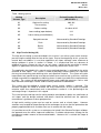
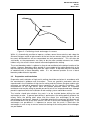
NR/CIV/SD/TUM/301 Rev P1 March 2011 TECHNICAL USER MANUAL For the Application of HIGH TENSILE NETTING and PASSIVE NON-STRESSED NETTING STANDARD DESIGNS AND DETAILS on ROCK SLOPES Page 1 of 33 NR/CIV/SD/TUM/301 Rev P1 March 2011 Summary This technical user manual provides guidance on the selection and application of Network Rail’s High Tensile and Passive Non-Stressed Netting standard detail drawings for the stabilisation and/or containment of rock slopes and containment of hybrid soil/rock slopes. Issue record This technical user manual will be updated when necessary by distribution of a complete replacement. Revision A P1 Date March 2008 March 2011 Comments First issue Second issue Page 2 of 33 NR/CIV/SD/TUM/301 Rev P1 March 2011 CONTENTS Section Description Page 1 INTRODUCTION ........................................................................................................................................ 4 2 SELECTION OF SYSTEM........................................................................................................................ 5 2.1 GENERAL ............................................................................................................................................. 5 2.2 HIGH TENSILE NETTING (N1).............................................................................................................. 6 2.3 PASSIVE NON-STRESSED NETTING .................................................................................................... 7 2.3.1 General .......................................................................................................................................... 7 2.3.2 Close Netted Face (N2) .............................................................................................................. 7 2.3.3 Open Base Loose Netting (N4) .................................................................................................. 8 2.3.4 Closed Base Loose Netting (N5) ............................................................................................... 8 2.4 NETTING SELECTION ........................................................................................................................... 8 3 HIGH TENSILE NETTING (ACTIVE SYSTEMS)................................................................................ 10 3.1 3.2 3.3 3.4 3.5 4 DESIGN PRINCIPLES AND GUIDANCE ................................................................................................ 10 PREPARATION AND INSTALLATION .................................................................................................... 11 LIMITATIONS....................................................................................................................................... 12 MAINTENANCE ................................................................................................................................... 13 EXAMPLE APPLICATIONS ................................................................................................................... 13 PASSIVE NON-STRESSED NETTING ................................................................................................ 14 4.1 DESIGN PRINCIPLES AND GUIDANCE ................................................................................................ 14 4.2 DESIGN METHODOLOGY.................................................................................................................... 14 4.2.1 General ........................................................................................................................................ 14 4.2.2 Close Netted Face (N2) ............................................................................................................ 15 4.2.3 Open Base Loose Netting (N4) ................................................................................................ 15 4.2.4 Closed Base Loose Netting (N5) ............................................................................................. 15 4.3 PREPARATION AND INSTALLATION .................................................................................................... 17 4.4 LIMITATIONS....................................................................................................................................... 18 4.5 MAINTENANCE ................................................................................................................................... 18 4.6 EXAMPLE APPLICATIONS ................................................................................................................... 20 ANNEX 1 TYPICAL EXAMPLES .............................................................................................................. 21 ANNEX 2 SCHEDULE OF STANDARD DETAIL DRAWINGS............................................................ 31 ANNEX 3 CALCULATION METHOD FOR CLOSED BASE LOOSE NETTING .............................. 32 Page 3 of 33 NR/CIV/SD/TUM/301 Rev P1 March 2011 INTRODUCTION 1 This Technical User Manual is aimed at providing advice on the application of netting systems to cuttings using the standard details shown on the Network Rail suite of standard details for earthworks. The netting systems are split into two distinct systems, the high tensile, active netting systems and the passive non-stressed netting systems. The differences between these systems will be made clear within this document. The standard details and issues addressed in this Technical User Manual relate to “rock” slopes. The term “rock” is used to differentiate between rock and soil slopes to the extent that no advice is given on methods of dealing with soil slope stability although the systems described can be used to deal with slopes containing soil usually in combination with weathered rock. For example, any containment system can be designed to contain soil in the same way as rock and there are many examples where the debris from a rockfall becomes a soil or slurry material when combined with water. Active systems are those which are designed to stabilise slopes so that the rock or soil does not have to move in order for the stabilisation system to generate restraint. Therefore it is expected that, in the case of netting systems, the netting exerts some form of stabilising force onto the slope material. Active systems require detailed investigation and design to ensure that they operate effectively and provide the desired level of reliability. Therefore only limited advice on system selection and details is given in the manual. In addition the active systems are generally constructed using proprietary systems and the advice from the specialist manufacturers or their technical literature should be sought during the design and specification stage. Passive systems are those that allow movement of the rock or soil before the reactive forces are generated by the system. This may involve a system that retains the material (a retention system) or one that allows the soil or rock to fall or slide in a manner that does not endanger the railway or associated infrastructure or personnel. This is referred to as a containment system. Examples of retention systems would be unstressed anchorages or netting placed locally around an isolated block of rock. Examples of containment systems are draped netting over a slope or rock catch fencing or debris barrier at the toe of a slope. This Technical User Manual and associated Standard Details deal with netting used in two particular applications which are: • Active high tensile netting retention systems • Passive non-stressed netting containment systems The active high tensile system described and detailed makes reference to a single proprietary system. This is necessary as it is not possible create generic configurations without reference to some particular system. Alternative systems may be available and, within the limitations described in the following sections, these alternative systems may be adopted with appropriate modifications to the specifications. The passive non-stressed netting systems are more generic and three alternative arrangements are described in this manual. However it has been necessary to refer to a particular netting system in order to develop the details. Consequently reference to particular manufacturer’s products or specifications should not be construed as advice to preclude the use of alternative systems, which can be relatively easily substituted providing the Scheme Designer accommodates the particular characteristics of the materials into the design and adjusts the specification accordingly. Page 4 of 33 NR/CIV/SD/TUM/301 Rev P1 March 2011 2 SELECTION OF SYSTEM 2.1 General The selection of a suitable system to protect the railway and associated infrastructure from failure of a cutting slope is a complex process involving geotechnical and risk assessment. The adoption of any of the standard configurations and details described in the manual and associated drawings should be considered within the option selection stage along with other alternative retention or containment systems which could include inter alia: • • • • • • • • Regrading and/or scaling Dentition and/or buttressing Drainage Shear trenches Soil nailing/rock bolting Electrokinetic systems Fences or debris barrier with or without rock traps Toe walls It should also be noted that the systems described are only intended to be applied to rock or mixed slopes and are not intended to be used where soil stabilisation is deemed to be necessary. The option selection process should examine the particular requirements of the site. If it is considered that it not acceptable for any failure of the slope to take place (for example properties or other conditions at the crest) then a stabilisation system will be required. Network Rail Standard NR/L3/CIV/071 requires that stability is ensured by applying partial factors to the actions and material properties (strengths) using the principles of BS EN 19971. A risk based approach may also be used for rock slopes. In considering the approach to be adopted consideration should be given to the potential cost of stabilisation of the slope at various risk levels compared to the cost of containment systems on a whole life costing basis. These costs should be combined with the additional planned maintenance and potential higher risk to the railway if the containment system becomes overloaded or fails in some other way. A quantitative risk analysis can be carried out in accordance with Network Rail’s Safety Case to evaluate the Net Safety Benefit of the various options to establish the preferred option and to justify the lower levels of certainty that may result from adopting a lower cost containment system. Table 1 below identifies nine potential elements of a netting scheme. This document considers design guidance for items N1 (high tensile netting), N2 (close netting), N4 and N5 (loose netting). Item N3 (contour netting) is considered to be a special case of N2 where the slope profile is not uniform. For this situation an irregular spacing of rock dowels will be required to ensure that the netting is restrained close to the rock face. Item N6 (sprayed concrete) is not covered by the standard drawings or this TUM. Items N7, N8 and N9 (ditches, barriers or bunds) may be used in conjunction with any netting system to provide additional protection to the railway, but detailed design procedures for these systems are not part of this TUM. It is emphasised that the ease and reduction of maintenance requirements are a key considerations in the selection of an appropriate system. Page 5 of 33 NR/CIV/SD/TUM/301 Rev P1 March 2011 Table 1 Netting options Netting Scheme Type Description Related Standard Drawing (NR/CIV/SD/…) N1 High tensile netting 300, 301 N2 Close netting 311 N3 Contour netting A subset of N2 N4 Loose netting (open bottom) 312 N5 Loose netting (closed bottom) 313 N6 Sprayed concrete Not covered by Standard Drawings N7 Ditch Not covered by Standard Drawings N8 Barrier Not covered by Standard Drawings N9 Bund Not covered by Standard Drawings 2.2 High Tensile Netting (N1) The high tensile netting system described in this manual is an active system which involves prestressing the netting onto the face of the slope. Due to the complexity of this system this manual does not address its use when applied to soil slopes although some reference to design guidance is given in section 3.1 below. It is emphasised that any absence of guidance of these systems for the use on soil slopes, should not be construed as advice against its application, which has been shown to be very effective on certain sites. The application described in this manual and associated drawings is restricted to the active retention of rock slopes. The system is aimed at providing surface stability to a rock face that may be weathering and releasing talus and superficial material. The system will retain larger blocks but specific design must be carried out to ensure that the system has sufficient strength to provide the appropriate stabilising forces in order to establish the required factor of safety. The system can be combined with larger scale stabilising measures such as rock bolts and rock anchorages used to stabilise clearly identified unstable blocks. The system may be applied to mixed slopes where surface stability is required. The Scheme Designer will need to evaluate the likely effectiveness of the system to provide retention rather than containment and, as described in section 3.1, the positioning of the anchorage fixings is important in this regard. The use of prestressed high tensile netting could be considered an option for stabilisation of soil slopes and the design methods and details should be derived from the specialist manufacturer’s guidance or other good practice. A high tensile netting system can be used on uneven rock or mixed slopes. However attention must be paid to the positioning of the anchorages to ensure that the preload can be properly applied and that all unstable areas are in contact with the netting. It is possible to use this system as an active/passive hybrid if the Scheme Designer validates the approach over the entire slope and establishes a suitable maintenance strategy for the management and/or removal of accumulated debris. However this is outside the scope of this manual. Page 6 of 33 NR/CIV/SD/TUM/301 Rev P1 March 2011 2.3 2.3.1 Passive Non-Stressed Netting General Passive non-stressed netting has been commonly used for many applications on the road and rail infrastructure over the past 50 years. The primary purpose being to ensure that rocks or debris released from a slope are not able to reach the infrastructure below in a way that endangers the users of that infrastructure. The method by which this protection is applied has not been extensively researched and some systems attempt to contain the material close to where it is released while other systems aim to direct the material to a debris trench or zone at the toe of the slope. Netting will also reduce the energy of falling material although it is difficult to make any quantitative assessment of this characteristic. The decision as to which approach to take should lie with the Scheme Designer who will need to judge how any released material will behave and how the netting shall contain this material. Future ease of maintenance is a key concern and should be considered at the design option stage. Maintenance activities to be considered at the design option stage should include the release of slipped rock and soil and the management of vegetation including trees. The maintenance regime that is set out in Section 4.5 will need to be considered in relation to the available possessions (Rules of the Route) and the strategy for the route noting that in some circumstances there will be a requirement for a maintenance free period which may result in this system being inappropriate for the application. Each slope is unique and therefore this manual can only give general guidance as to which system is most appropriate. This system may be combined with other systems such as the individual anchoring of large blocks that may exceed the capacity of the system if they become detached. 2.3.2 Close Netted Face (N2) A close netted face is one where the netting is pinned against the face and as a consequence it is not expected that any significant rockfall will travel down the slope to the toe. The general arrangement of a typical system is shown on drawing NR/CIV/SD/311 and would usually be applied to reasonably uniform slopes. It is likely that debris will trickle down to deposit small quantities at the toe. A simple application of a close netted face is to stop superficial talus on a slope sliding down a slope and blocking the cess. Normally the quantities would be quite small such that the netting would not become highly stressed or bulge at the intermediate cable positions. An alternative application where a particular area of fractured rock exists would be to increase the intensity of rock dowels in the vicinity of the fractures to locally contain the material. In this circumstance, consideration should be given to using a pre-stressed high tensile netting solution instead which is likely to prove more effective than close netting. One advantage of this system is that it can be curtailed at a high level. A typical example would be where a steep slope runs from the top of a cutting to a small intact rock face or retaining wall at cess level. In this case it would be difficult, but not impossible, to provide some form of retention at the top of the wall or rock face and therefore this option can be considered. When this system is used consideration must be given to the maintenance requirements and the need to periodically release trapped material which is overloading the netting and rock dowels. Therefore, whilst installation is relatively straightforward, it can be used where a cess is restricted and can be curtailed at any level, it should only be adopted when the expectation of a rockfall or rockslide is low. Page 7 of 33 NR/CIV/SD/TUM/301 Rev P1 March 2011 2.3.3 Open Base Loose Netting (N4) Open base loose netting is the simplest form of netting and an example arrangement is shown on drawing No NR/CIV/SD/312. The arrangement can be used on slopes where there is sufficient space at the toe for any anticipated rockfall to accumulate without endangering the dynamic profile of the train or any lineside equipment such as location cabinets or OHLE masts. The netting should be configured to direct any rockfall to the toe of the slope, reduce the velocity of the rockfall and any tendency to kick away from the slope face during its descent. The slope topography will influence the decision as to whether intermediate anchorages are appropriate to fulfil the basic requirements. The length of the ties between the netting and the anchorages shall be a function of the expected volumes of rockfall, slope topography and available room at the toe. 2.3.4 Closed Base Loose Netting (N5) Closed base loose netting can be used where there is limited room at the toe of the slope to contain material. This system can be engineered to a greater extent than the other two options in that given a defined quantity of slipped material, the forces in the supporting netting and cables can be derived for a given slope geometry. A potential method for deriving forces and capacity is set out in section 4.2.4. The configuration of this system is shown on drawing NR/CIV/SD/313. This configuration can be adopted for rock and debris slopes of all angles and is also appropriate for soil slopes where the likely slip volumes can be predicted. Where the cess width is limited the arrangement is beneficial in giving greater reliability and relative ease of maintenance when compared with the close netted face. 2.4 Netting Selection The standard details provide good practice but they are not meant to be used without careful thought and analysis by the Scheme Designer to ensure that the systems achieve the desired outcomes and have sufficient strength to resist the anticipated forces. The guidance given in this Technical User Manual aims to facilitate appropriate levels of design consideration for netting solutions. Figure 1 provides a flow chart to guide the Scheme Designer through the selection of an appropriate netting solution. When selecting a netting solution the key decision is whether or not the slope requires stabilisation. Where the risk of overall slope failure is acceptably low or the consequence of a failure is not critical to the safe operation of the railway a full stabilisation scheme is unlikely to be required. The decision then revolves around whether there is potential for loose material to be dislodged from the face by rainfall, burrowing animals, tree jacking, ice wedging or any other mechanism. Based on the assessed volume of displaced material and the available width of the cess decisions may be made as to the type of passive netting required. Where the risk of overall slope failure is high or there is potential for significant volumes of rock to topple or slide out of the face more positive retention systems may be required. For these situations active netting may be employed where tensioning of the netting imparts forces into the face to restrain loose blocks. The design of an active netting system is outlined in Section 3 below, however for the system to work it must be possible to anchor the netting back into stable rock behind the rock face and the volumes of rock to be supported must be such that the strength of the netting is not exceeded. Consideration may also need to be given to restraining particularly large unstable rock masses with further rock bolts or anchors. For added protection ditches, bunds and/or rock barriers may also be employed at the base of the slope. These may be used as the sole protection measure where the slope is deemed to be essentially stable and there is sufficient width of cess to accommodate them. They Page 8 of 33 NR/CIV/SD/TUM/301 Rev P1 March 2011 may also be employed in conjunction with a netting solution where it is deemed that there is a risk of material not being adequately restrained by the netting and spilling on to the track. This is most likely to be the case for a loose netting open bottom solution. NO No special measures, monitoring regime to be continued. 1. Is the rock slope liable to degrade or susceptible to toppling failure? NO • • • YES 2. Does falling material require lateral restraint? DITCH (N7) BARRIER (N8) BUND (N9) YES • • • • ACTIVE HIGH TENSILE NETTING (N1) Provides surface stability by applying a stabilizing force to the slope face Uneven rock or mixed slopes Loose material locally retained Low maintenance requirements CLOSE NETTING (N2) • Loose material locally retained • Low maintenance frequency, but debris clearance more difficult • Small volumes of loose material expected on uniform slopes • Can be curtailed at any level PASSIVE YES LOOSE NETTING OPEN BOTTOM (N4) • Netting to steer material to base of slope • Higher frequency of maintenance but with easy access to debris YES 4. Slope with potentially Slope small volumes of loose uniform? unstable material? NO CONTOUR NETTING (N3) • Irregular rock face • Irregular rock dowel spacing • Potential for over-stressing netting and rock dowels LOOSE NETTING CLOSED BOTTOM (N5) • Netting to steer and retain material at base of slope, maintaining track clearances • Higher frequency of maintenance but with easier access to debris c.f. close netting • Higher forces in netting c.f. loose netting 3. Active or passive containment required? NO RESTRICTED 5. Available cess clearance? GOOD Figure 1 Selection of an appropriate netting solution Page 9 of 33 NR/CIV/SD/TUM/301 Rev P1 March 2011 3 HIGH TENSILE NETTING (ACTIVE SYSTEMS) 3.1 Design Principles and Guidance The design of high tensile active netting systems (N1) is quite complex and requires both an understanding of slope and rock stability analysis as well as a practical understanding of the installed behaviour of the system. This section of the manual is not intended as a complete design guide for the system but sets out the basic design principles that are used by the proprietary system and are applicable to other equivalent systems. This section also gives a certain amount of generic design guidance which will need to be verified and expanded on by the Scheme Designer. The proprietary system on which the standard details are based is manufactured by Geobrugg and uses TECCO mesh as the netting material. TECCO mesh has certain critical features which make it appropriate for use as an active netting system. These features are combined to produce a mesh which is flexible yet extremely strong and most importantly does not creep under load. Therefore once it is stressed it retains its preload without significant loss. The mesh is a diamond interlocking configuration using 3 mm diameter high tensile steel (yield strength >1770 MPa) resulting in a mesh tensile strength of 150 kN/m. Furthermore the diamond link enables the mesh to accommodate high punching loads either from the prestressed rock bolts or from contact over rock edges without local failure or stretching of the mesh. Geobrugg have introduced a stronger system (the SPIDER system) combining spiral rope and mesh netting which may be appropriate for certain applications. Reference should be made to the particular manufacturer’s design guides for detailed design guidance which may then need to be refined to deal with the particular application and railway environment. The configuration considered by this manual and the standard details is a relatively uniform slope containing loose and possibly unstable rock as depicted in drawing NR/CIV/SD/300. The netting is prestressed onto the face of the rock to generate a normal force on the face of the rock equal to the sum of the prestressing forces in the rock anchorages. This normal force can be used as a stabilising force in the stability analysis for the rock slope. Additional rock anchorages can be introduced to provide additional stability to certain unstable areas where the normal force from the netting alone is insufficient. Certain rock anchorages can be used both to prestress the netting and to provide stability to the rock where spare capacity exists in the anchorage over and above that required for the prestress force (incorporating appropriate partial factors). The positioning of the rock anchorages is critical to the success of the scheme. Firstly all anchorages must be positioned in a recess so that the entire preload is directed into the netting. A typical arrangement for a recess is shown on drawing NR/CIV/SD/301 and in this configuration Geobrugg suggest that the prestress load can be as high as 50 kN. However it is recommended that the prestress force is limited to 30 kN which is the maximum recommended by Geobrugg where the terrain is uneven as shown in Figure 2. Page 10 of 33 NR/CIV/SD/TUM/301 Rev P1 March 2011 Max 30kN Figure 2 – Positioning of rock anchorages in a recess Whilst it is theoretically possible to impose a uniform normal force onto the rock slope the Scheme Designer needs to take account of the fact that on uneven slopes the force will not be evenly distributed but will be concentrated on rock promontories. This will often be satisfactory as the promontories are likely to be the more unstable elements but sizable hollows may also result in loose material accumulating below the netting. The use of boundary cables is optional as they do not contribute to the design function of the netting. However, boundary cables provide a secure edge to the netting particularly at the top and stop the mesh peeling away from the slope surface. A top cable may be used alone or combined with a lateral boundary cable. It is not common practice to use a lateral boundary cable without a top cable. 3.2 Preparation and Installation Preparation and installation of high tensile netting should be carried out in accordance with the manufacturer’s guidance and instructions. There are specialist contractors who are experienced in the installation of high tensile netting and the Scheme Designer and/or main contractor are advised to approach these companies for this specialist installation. The manufacturers of the high tensile mesh will provide particular advice on installation techniques and may be willing to provide personnel to train an inexperienced team although previous experience with the installation of rock netting systems would be essential. The installer should plan whether the mesh is to be installed before drilling the rock anchorages or after. In general post-drilling is preferred as the netting partially protects the railway whilst the drilling takes place and also allows the anchorages to be most advantageously positioned. However, it should be noted that the maximum drill diameter will be restricted to the size of the mesh (which is 65 mm in the case of Geobrugg mesh). If the anchorages are pre-drilled it is important to ensure that the mesh is fitted over the anchorages in such a way to ensure correct tensioning of the netting when the anchorages are pre-loaded. Page 11 of 33 NR/CIV/SD/TUM/301 Rev P1 March 2011 The slope surface will need to be prepared so that it is suitable for the installation of the mesh. In general this means that all vegetation shall be removed from the slope and all tree stumps shall be cut back to 20 mm proud of the slope or flush with the slope if possible and treated to prevent re-growth. Loose boulders and any detritus should also be removed. More extensive scaling, removal and where necessary strengthening works may also be necessary as required by the scheme design. Where it is deemed preferable to leave large loose material in place an arrangement of mesh and anchorages should be devised in order to safely retain the material. However, consideration will need to be given to the risks of installing anchorages below potentially loose material. Groundwater management may need to be included as part of the design and installation strategy. Aggressive groundwater may need to be directed away from anchorage locations. Holes for trees can be accommodated into the design in exceptional circumstances and the manufacturer’s guidance should be sought in respect of suitable strengthening details around any opening in the mesh. However, it is not advisable to leave live trees on rock slopes as root wedging is likely to lead to further rock fracture which may be outside the capacity of the mesh and anchoring system. Connections between the mesh panels must be fully in accordance with the manufacturer’s instructions and it is emphasised that these connections are a fundamental aspect of the performance of the system and should not be compromised under any circumstances. It is recommended that horizontal connections are avoided wherever possible. Rock bolts and spike plates shall be positioned and oriented so that the spike plates engage the mesh as evenly as possible and that the anchorages are set at right angles to the spike plates when tensioned. Where there is a large gap between the mesh and the rock (as depicted in Figure 2), care is needed to ensure that these criteria are met. Positioning of the anchorages and installation of the spike plates on the perimeter of the mesh requires care and as noted above, consideration shall be given to the use of boundary cables to provide a more robust perimeter to the mesh. The cables can be threaded through the mesh or attached with press claws at regular intervals as well as being clamped by the spike plates. Additional short auxiliary (non-structural) anchorages may be installed to ensure the boundary follows the profile of the ground. It is preferable to continue the top (crest) edge of the mesh above the top line of anchorages and secure it behind the crest of the slope. Typically the mesh should be taken at least 2 m beyond the crest of the slope but shorter distances may be justified where there is restricted access and the ground at crest level is sufficiently competent. The system for securing the top edge of the mesh will require the use on non-structural anchorages, typically short drilled rock dowels in competent rock or driven nails in overburden materials. 3.3 Limitations The high tensile mesh has applications covering a wider range of slope conditions than is covered in this TUM which is restricted to rock slopes only. Any application of high tensile mesh in other circumstances is outside the scope of this TUM. The details set out in the standard designs for high tensile netting enable superficial material to be actively retained on the rock face. Where it is necessary to retain more substantial volumes of rock, rock bolts shall be designed specifically to stabilise the particular elements in accordance with good rock mechanics engineering practice and shall be in addition to anchorages required to retain the mesh system unless a fully integrated design is carried out. Page 12 of 33 NR/CIV/SD/TUM/301 Rev P1 March 2011 3.4 Maintenance One of the principal reasons for selecting the high tensile netting system is that it should not require maintenance under normal circumstances. Although loose material may build up in small hollows, providing the netting has been well designed and installed, the loose material should be safely retained and not need removing. It is possible that surface deterioration over the medium term may result in a loss of tension in the netting and a re-tensioning programme will improve the condition of the slope. Provided the rock anchorages have been installed in suitable hollows, re-tensioning should be a relatively straightforward process. However, reference should be made to the original design before defining re-tensioning loads. Additional rock anchorages can be installed should the slope deteriorate to such an extent that the original design requires enhancing. Generally it should be possible to carry this out without removing any of the existing mesh and anchorages. Table 2 summarises the inspection and maintenance programme should be adopted for high tensile mesh systems. Table 2 High tensile mesh inspection and maintenance programme. Period Inspection Possible maintenance or enhancement activity After first year and then at 2 year intervals Visual examination for loose areas, broken sections or failed rock anchorages None anticipated. Replace broken sections, install additional anchorages in appropriate areas 10 years Abseil inspection. Check as for 5 year inspection plus residual tension in netting Re-tensioning of netting if required. Remediation as for 5 year period (not anticipated) 20 years Abseil inspection as for 10 year inspection. Examine for corrosion of netting and anchorages As per 10 year period. Replace any corroded netting 3.5 Example Applications The following sites give examples of the application of high tensile netting to rock slopes on railway cuttings: (a) Kyle-Duncraig KYL 56m 08ch – 56m 78ch (b) Winterbourne Cutting SWB 109m 71ch – 110m 23ch Page 13 of 33 NR/CIV/SD/TUM/301 Rev P1 March 2011 4 PASSIVE NON-STRESSED NETTING 4.1 Design Principles and Guidance The design principles that can be adopted for the design of the passive non-stressed netting and its attachments are by their very nature approximate. The degree of accuracy that the Scheme Designer should attempt to achieve should reflect the accuracy of the primary design input, i.e. the quantity and configuration of the material to be retained. With all the configurations of passive non-stressed netting, the Scheme Designer will need to consider the potential failure modes of the material to be retained and the manner in which the material behaves while it is falling down the slope, how it is brought to rest and the final state when the material is at rest using engineering principles. In all these modes the primary design objective is to ensure the safety of the trains and critical infrastructure with the secondary objectives of avoiding damage to the less critical infrastructure, the capacity to resist a secondary rockfall and the maintenance requirements following the rockfall. In general the netting manufacturers provide a reasonable amount of data on the strength of the mesh materials and will also provide data obtained from a range of tests carried out on the various products. Intelligent use of such data will aid the Scheme Designer to create netting systems with compatible strengths between various components and the expected applied loads. 4.2 4.2.1 Design Methodology General The suggested design methodology to be used for the three passive netting arrangements described below is centred around ensuring vertical and horizontal equilibrium and minimizing eccentric (i.e. non-axial) loads on rock anchorages. The key design parameters are likely to be as follows: • • • • • • Size and type of failure to be managed System design life Mesh tensile strength Mesh punching strength Anchorage capacity Cable strength Partial factors for the various components used in the system should take into account the risk associated with the individual components and configurations in which they are used (for example eccentric or uneven loading). However, the Scheme Designer should be aware that the high factors used for defining “safe working loads” for cables and fittings such as turnbuckles or Dee shackles generally used for lifting equipment may not be appropriate for these applications. Reference shall be made to the relevant European standards when designing the netting system components with particular consideration given to potential elongation of wire cables if they are to be used under high design loadings. The Scheme Designer will need to develop sufficient knowledge of the rock characteristics in order to ensure that the anchorages that are specified have sufficient capacity. It is often the case that weak superficial material may penetrate to a significant depth and therefore the anchorage design may need to be adapted to accommodate these conditions. Design and testing of the anchorages will need to follow normal good practice relating to all rock anchorages with due consideration of the criticality of the particular anchorages in relation to the performance of the system as a whole. Page 14 of 33 NR/CIV/SD/TUM/301 Rev P1 March 2011 4.2.2 Close Netted Face (N2) The design considerations for a close netted face are likely to be the risk of local punching of the netting at an intermediate rock anchorage position. The Scheme Designer will need to estimate the reaction force required at each anchorage position normal to the face resulting from the displaced material and make suitable comparisons with the punching capacity and/or tensile capacity of the netting. It is likely that the material (and therefore the applied force) will be applied on the upper side of the anchorage only and this is likely to result in a reduction in the punching capacity compared with a symmetrical test. Punching failure of the netting should ideally be designed out by treating individual blocks that may cause this form of failure by removal, bolting or dowelling of the block. If large volumes are anticipated the use of a close netted system is not likely to be the appropriate option. The use of an intermediate horizontal (or diagonal) cable has the advantage of retaining material more effectively at the intermediate level whilst its omission will enable the material to fall or slip down the slope between the anchorages. The omission of intermediate cables may result in more material being deposited at the base of the netting (which may be easier to maintain) but an unpredictable amount will be retained in the vicinity of the anchorage points. Therefore the cable will enable a more designed approach to be used although the loading at each level may be greater. Maintenance issues will also influence the decision as to whether an intermediate cable is appropriate as different slope profiles will have different requirements. Consideration may also be given to the use of diagonal cables where they can be applied along with intermediate anchorages to the contoured face of the rock to improve contact between the netting and the rock. 4.2.3 Open Base Loose Netting (N4) Open base loose netting is not intended to retain any material and as a result it is difficult to prepare quantitative calculations to demonstrate suitability although overall forces can be considered. In configuring the design of an open base loose netting system, the Scheme Designer should give consideration to the expected volumes of rockfall and the size of individual rocks along with the available room at the toe. Whilst this configuration is probably capable of managing larger rockfall quantities than the other two configurations, the energy of a large falling rock has the potential to rip normal mesh especially if it has sharp edges. Intermediate and base anchorages and the mesh attached to these can be damaged if the rocks impact these areas directly. As a result the use of intermediate anchorages is only really desirable if the slope topography is concave. The use of horizontal cables can be beneficial to reduce the risk of the mesh splitting at these locations if the intermediate anchorage locations allow a logical cable configuration to be developed. 4.2.4 Closed Base Loose Netting (N5) Closed base loose netting has the advantages explained in section 2.3.4 above in that it can be engineered to a greater extent in comparison with the other two options and it can ensure that a defined quantity of slipped material can be retained so that it does not encroach into the dynamic profile of the train. Nevertheless the system has the disadvantage that the retained material places considerable loads on the netting and restraining cables and relies on substantial anchorage of the vertical cables at the top of the slope. The two principal parameters that influence the design of the system are the volume of material to be retained and the distance that the netting can project from the base of the slope without encroaching into the dynamic profile of the train or damaging other infrastructure. Therefore it is important to accurately survey the toe of the slope in order to define the point at which the bottom anchorage is installed. Consideration will need to be given to the angle of the toe anchorage to limit the eccentricity under the design conditions Page 15 of 33 NR/CIV/SD/TUM/301 Rev P1 March 2011 and method of installation. The use of proprietary wire rope anchorages gives improved flexibility at this location. In order to provide adequate anchorage at the top it is recommended that a top cable fixing detail is used that provides resistance through direct axial force on the anchorages through triangulation (e.g. details T2a and T2b, NR/CIV/SD/314) rather than rely on bending resistance and local passive resistance of the soil (e.g. details T1a and T1b, NR/CIV/SD/314). Alternative details using a saddle and back anchorage have been successfully used in this application. Some consideration can be given to the friction loss where the cable and, if applicable, netting changes angle at the crest of the slope although this reduction is difficult to evaluate and in some circumstances is quite a small proportion of the load. The arrangement from which the forces can be derived is shown in Figure 3. Top Anchorage to resist cable tension Dynamic clearance limit Slipped Material (design volume) Toe Anchorage Figure 3 – Closed base netting arrangement The length of cable is clearly critical to ensuring that the dynamic clearance is maintained under the design volume of material. Therefore the actual cable length can only be established once the relationship between the top anchorage, crest and toe anchorage is known. It is suggested that once installed the relevant points are surveyed and the cable length calculated on the basis of the surveyed dimensions with due allowance for cable and netting stretch. The toe anchorage is an important component and the envisaged shape of the base portion of the netting containing the slipped material will define the direction of force on the toe anchorage. It is preferable to select the angle of the toe anchorage so that the force from the cable is axial and does not contain a lateral component which will generate bending Page 16 of 33 NR/CIV/SD/TUM/301 Rev P1 March 2011 moments in the anchorage. Proprietary anchorage systems using spiral ropes as opposed to rigid bar enable flexibility of approximately 15 degrees to be achieved and are therefore appropriate in these locations. A method that has been used for the calculation of cable tensions and anchorage loads and angles is included in Annexe 3. This is included for information only and the Scheme Designer should be satisfied that the netting configuration, dimensions and component forces are appropriate for the particular application. 4.3 Preparation and Installation The installation of mesh and, where appropriate, other components should be carried out in accordance with the manufacturer’s instructions and guidelines. In general for all three applications (N2, N4, N5) it will be preferable to install the anchorages on the slope before installing the mesh. However, for the Close Netted Face (N2) it is possible to install slope anchorages after installation of the mesh although consideration will need to be given to the drill diameter in relation to the mesh size. It is not recommended that the mesh should be cut at an anchorage position to enable a larger drill size to be used unless the mesh capacity can be demonstratively reinstated as it is likely that for the punching condition this location represents the position of maximum stress. The mesh will normally be placed by placing a roll of mesh at the top of the slope and lowering the roll down the slope in a controlled manner. Occasionally it may be more convenient to place the roll at the base of the slope and raise the netting using a winch or crane, but this is less likely in railway cutting applications. The slope surface will need to be prepared so that it is suitable for the installation of the mesh. In general this means that all vegetation shall be removed from the slope and all tree stumps shall be cut back to 20 mm proud of the slope or flush with the slope if possible and treated to prevent re-growth. Loose boulders and any detritus should also be removed. Where it is deemed preferable to leave large loose material in place an arrangement of mesh and anchorages should be devised in order to safely retain the material. However consideration will need to be given to the risks of installing anchorages below potentially loose material. Holes for trees can be accommodated into the design and the manufacturer’s guidance should be sought or suitable designs and details should be prepared in respect of strengthening details around any opening in the mesh. However, it is not advisable to leave live trees on rock slopes as root jacking is likely to lead to further rock fracture which may be outside the capacity of the mesh and anchoring system. Groundwater management may need to be included as part of the design and installation strategy. Aggressive groundwater may need to be directed away from anchorage locations and other sensitive parts of the system. Connections between mesh panels shall be made using tool closed stiff wire clips at suitable centres. It is recommended that the minimum spacing should be alternate hexagonal panels as shown on drawing NR/CIV/SD/316. Alternative connection details may be adopted with reference to the relevant manufacturer’s details and test data but it is emphasised that the vertical connection is likely to be the weakest part of the mesh. Where a vertical cable is used along the seam the cable should be connected with standard wire rope grips in accordance with manufacturer’s guidance. For the close netted face option (N2) it is important that the anchorages are placed in such a way that the netting adheres closely to the slope face. Horizontal and diagonal cables may Page 17 of 33 NR/CIV/SD/TUM/301 Rev P1 March 2011 be installed to assist in achieving this objective. The practice of using short pins to assist with this objective will only be successful if the pins can be anchored into sound rock. A number of the connection details shown on drawings NR/CIV/SD/314-316 show thimbles attached to closed eyes (e.g. the eye detail on the fixing plate). In order to install the thimble, it will need to be cut at its apex and opened out to fit onto the eye. Experience has shown that some contractors are happy to do this while others would prefer to install a Dee shackle between the eye and the thimble. 4.4 Limitations The primary limitation for any form of passive netting is that movement of the soil or rock has to take place before the retention system acts. Therefore failure of some form has to have taken place. This results in a future maintenance liability for the asset manager which is described in the following section. Passive netting systems also suffer from the difficulty of predicting both the disturbing forces that are applied to the system by the detached material and how the passive netting system can provide resistance to those forces that arise. Consequently, both sides of the equation are uncertain and a significant amount of engineering judgement needs to be applied in the design and detailing of the system. The purpose of developing the Standard Details and this TUM is to improve the consistency and reliability of the systems being installed onto the railway infrastructure. 4.5 Maintenance It is expected that the Scheme Designer will propose a maintenance strategy as part of the detailed design and that the anticipated future maintenance liabilities are highlighted in the Form A when used for a complex scheme. Whilst it is possible that some schemes will be maintenance free, the purpose of a passive system is to contain loose material and the overall scheme should be conceived in the expectation that some debris will accumulate in locations that will be dependent on the selected netting option. Maintenance should be considered on two levels. Firstly, maintenance involving the removal of slipped material when there is sufficient material to suggest that further failures will result in damage or failure of the netting system or its components or that clearances may be at risk. Secondly, maintenance when there has been some damage to the netting system and its components or when life expired components require replacement. Inspection of the system should be carried out on a regular basis and schedules used for previous applications have proposed monthly inspections from a foot patrol between May and September and fortnightly between October and April. This would be applicable to a relatively high risk slope and less frequent inspections may be appropriate for lower risk slopes. The structural components of the netting system should be inspected for visual damage on an annual basis and a detailed inspection using roped access should be carried out on a 10 year cycle. At the same time destructive vegetation, such as trees, should be removed and treated to prevent re-growth. It is recommended that planned periods are scheduled for the removal of slipped material. This will reduce the number of unplanned possessions that may be required to clear excessive debris from behind the netting. This will be a matter for Network Rail to decide and the Scheme Designer should give realistic estimates of the amount of debris that may fall during any annual period. It is suggested that the initial periods are set as being annual in the early spring of each year after the wet winter period. The period may be increased in Page 18 of 33 NR/CIV/SD/TUM/301 Rev P1 March 2011 future years with greater knowledge of the behaviour of the slope and re-establishment of managed vegetation. Exceptional removal of material may be required as a result of significant slips or where the netting system has been damaged. The Territory Geotechnical Engineer may wish to engage specialist geotechnical advice as to whether the removal should be immediate or whether it will remain stable until the next available possession. A detailed inspection of the structural components should be carried out in the area of a slip when the debris is being cleared out. The removal of debris can present considerable difficulties and risks to the removal gang. When the system is retaining large quantities of material it is likely that there will be considerable tension in the netting, cables, anchorages and associated components. For small quantities of material the provision of turnbuckles at 30 metre centres should aid the de-tensioning of horizontal cables and allow the release of the debris into the cess. This will vary between the various systems and it may be necessary to release mid-height anchorages on the close netted face system to allow debris to drop down the face and a risk assessment and methodology will be required to enable this to be carried out safely. For the open base system it is possible that the debris can be removed without any effect on the netting whilst the closed base system will require the bottom horizontal cables to be released as a minimum. When there is a large quantity of material it is likely that the material cannot be released by loosening various cables and components. In this case the material should be released by cutting the tying clips or wires between the netting panels and releasing material in a controlled manner. Similarly the lap joint at the bottom cable can be released. If this is not possible the netting can be cut just above the bulge of slipped material to allow the material to be released. This should be done one panel at a time. However, a particular risk assessment and methodology should be developed for each condition and the outline methods described above should only be used as a guide. Table 3 summarises a typical maintenance regime which can be used as a basis. Table 3 Typical Maintenance Regime Period Inspection Possible maintenance or enhancement activity Monthly Visual examination from track or opposite crest for debris build up (by patrolman) None anticipated. Report any debris build up. Arrange for further inspection if necessary 1 year Visual inspection of netting and components from cess or opposite crest by engineer. Pre-inspection for planned maintenance Any repairs identified to be carried out during planned maintenance. 1 year (or less frequent) Planned maintenance Planned maintenance activity with booked possessions is proposed to remove annual debris build up and minor repairs if required. 10 years Abseil inspection of netting and components. Check for corrosion at anchor heads. Possible local repairs to netting damaged by vegetation etc. Removal of destructive vegetation. Unplanned Special examination Removal of unexpected debris build up and repairs as required. Page 19 of 33 NR/CIV/SD/TUM/301 Rev P1 March 2011 4.6 Example Applications The following sites give examples of the application of passive non-stressed netting on rock slopes on the railway infrastructure and selected photographs are included in Annexe 1: Gatcombe SWM 129m 07ch – 130m 35ch Kyle-Duncraig KYL 56m 08ch – 56m 78ch Dawlish Sea Cliffs MLN 207m 53ch – 208m 57.5ch Shaldon Quay MLN 209m 60ch Winterbourne Cutting SWB 109m 71ch – 110m 23ch Fly Arch Cutting MLN1 228m 67ch – 229m 09ch Page 20 of 33 NR/CIV/SD/TUM/301 Rev P1 March 2011 ANNEX 1 TYPICAL EXAMPLES Example 1. Kyle-Duncraig (KYL 56m 08ch – 56m 78ch): High Tensile Netting System on left, Open base loose netting on right. Example 2. Kyle-Duncriag (KYL 56m 08ch – 56m 78ch): High tensile netting top detail on left. Open base loose netting on right. Note the area where additional anchorages have been installed to provide additional stability separate from the netting system. Page 21 of 33 NR/CIV/SD/TUM/301 Rev P1 March 2011 Example 3. Kyle-Duncraig (KYL 56m 08ch – 56m 78ch): High Tensile Netting. Note positioning of anchorages in hollows to ensure the netting is prestressed against the rock when the claw plates are tightened. Example 4. High Tensile Netting. A typical arrangement of anchorages positioned in the hollows to ensure netting is prestressed. Page 22 of 33 NR/CIV/SD/TUM/301 Rev P1 March 2011 Example 5. High Tensile Netting. Detail of anchorage and press claw Example 6. Winterbourne Cutting (SWB 109m 71ch – 110m 23ch): High Tensile Netting. Note the separate stabilisation of the rock band that was considered to be too large to be stabilised by the high tensile mesh alone. Note the mesh has not yet been tensioned in the photograph. Page 23 of 33 NR/CIV/SD/TUM/301 Rev P1 March 2011 Example 7. Gatcombe Cutting (SWM 129m 07ch – 130m 35ch): Closed Base Netting. In the foreground the “bag” can be seen empty but in the distance a slip has partially filled the “bag” at the base. Example 8. Gatcombe Cutting: (SWM 129m 15ch). A large rock fall has been retained by closed based netting which has protected the location boxes. Additional bottom and vertical cables have been added to prevent overstress of the netting system. Page 24 of 33 NR/CIV/SD/TUM/301 Rev P1 March 2011 Example 9. Gatcombe Cutting: (SWM 129m 07ch – 130m 35ch). A massive rockfall in excess of twice the “design” condition has been contained by the closed base system. Additional cables have been added after the event due to overstressing of the top anchorages. Some damage has occurred to the netting and the intermediate anchorages (detail M2) have pulled out. Page 25 of 33 NR/CIV/SD/TUM/301 Rev P1 March 2011 Example 10. Fly Arch Cutting (MLN1 228m 67ch – 229m 09ch): Close Netted Face. Note that Geomat has been placed under the netting to encourage vegetation. Example 11. Shaldon Quay (MLN 209m 60ch): Closed Base Loose Netting showing detail B1 and horizontal cable end with turnbuckle. Note that the edge vertical cable is tight to avoid side spill. Page 26 of 33 NR/CIV/SD/TUM/301 Rev P1 March 2011 Example 12. Shaldon Quay (MLN 209m 60ch): Closed Base Loose Netting Page 27 of 33 NR/CIV/SD/TUM/301 Rev P1 March 2011 Example 13. Dawlish Sea Cliffs (MLN 207m 53ch – 208m 57.5ch). Open Base Loose Netting. Note that the gully has been fully remediated using a close netted face system with anchorages and geomat and the upper sections of the slope have been also been fully remediated. Page 28 of 33 NR/CIV/SD/TUM/301 Rev P1 March 2011 Example 14. Turnbuckle detail for horizontal cable Example 15. Detail B3. Note that the anchorage has not yet been tightened. Page 29 of 33 NR/CIV/SD/TUM/301 Rev P1 March 2011 Example 16. Detail T3 Page 30 of 33 NR/CIV/SD/TUM/301 Rev P1 March 2011 ANNEX 2 SCHEDULE OF STANDARD DETAIL DRAWINGS Drawing Description NR/CIV/SD/300 NR/CIV/SD/301 NR/CIV/SD/310 NR/CIV/SD/311 NR/CIV/SD/312 NR/CIV/SD/313 NR/CIV/SD/314 NR/CIV/SD/315 NR/CIV/SD/316 High Tensile Netting, General Arrangement High Tensile Netting Typical Details Passive Non-Stressed Netting General Arrangement Passive Non-Stressed Netting Close Netted Face Passive Non-Stressed Netting Open Base Loose Netting Passive Non-Stressed Netting Closed Base Loose Netting Passive Non-Stressed Netting Top Details Passive Non-Stressed Netting Base Details Passive Non-Stressed Netting Intermediate and Miscellaneous Details Page 31 of 33 NR/CIV/SD/TUM/301 Rev P1 March 2011 ANNEX 3 CALCULATION METHOD FOR CLOSED BASE LOOSE NETTING Top of Slope Slope Face Top of retained material Wm = Im = Km = Fh= Material Density Impact Factor Lateral pressure coefficient Total lateral Force from material Hs T4 x Sin(Ar) + Gx - R2 +R1 - R3 R2 = (Hs-Hm)/Tan(As) R3 Z y x Hm - T4 x Cos(Ar) Anchorage Offset Gx Hm Bulge Offset Fh T4 As Ar Aa T4 x Sin(Ar) R1 = Hs/Tan(As) Fh = Wm x Im x Km x Hm2/2 R4 Equation for the shape of the cable/netting can be defined as a cubic polynomial: y = Ax 3 + Bx 2 + Cx + D The cable/netting curvature is: ∂y = 3 Ax 2 + 2 Bx + C ∂x The applied load is linked to the second derivative: ∂2y = 6 Ax + 2 B ∂x 2 Page 32 of 33 NR/CIV/SD/TUM/301 Rev P1 March 2011 The equation of the cable/netting is defined as being at the top of the retained material where the lateral load is zero. Hence: x = 0: ∂2y = 0∴ B = 0 ∂x 2 x = 0 : y = 0∴ D = 0 End point: ∂y = −Tan ( 90 0 − Ar ) = C ∂x x = Hm : y = R 2 + R 3 − R1 − Gx Hence: ( R 2 + R 3 − R1 − Gx ) = A ( Hm ) 3 − Tan ( 90 0 − Ar ) Hm x = 0: y = 0: Netting angle: ( R 2 + R 3 − R1 − Gx ) + Tan ( 90 0 − Ar ) Hm A= Hm 3 The equation of the cable/netting curve is now defined and can be transposed as required into global axes. The base anchorage angle (Aa) can be established from this equation which is an important parameter if the anchorage is to avoid lateral forces and is required for the derivation of cable forces which are derived as follows: Fu Ar Fh Aa Fb Resolving Forces: Horizontal: FuCos ( Ar ) + FbCos ( Aa ) = Fh Vertical: FuSin ( Ar ) = FbSin ( Aa ) Hence: Sin ( Aa ) Fu = Fb Sin ( Ar ) Sin ( Aa ) Fh = Fb Cos ( Ar ) + Cos ( Aa ) Sin ( Ar ) Hence the cable forces can be calculated The volume of material and cable length can be calculated by integration of the derived equation. In order to turn these equations into a useful design tool it is necessary to be able to derive the forces, anchorage angle and cable lengths from the primary design input parameters (i.e. the slope height and angle, volume and type of material to be retained, the anchorage and bulge offset). This can be achieved by a double iteration and numerical integration using spreadsheet macro or computer program. Page 33 of 33