1
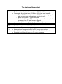
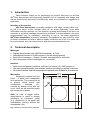
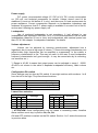
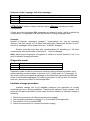
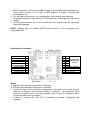
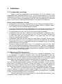
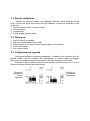
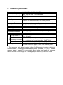
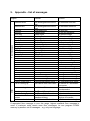
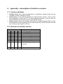
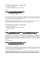
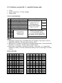
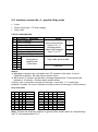
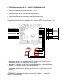
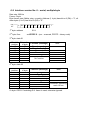
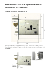
® 2N Floor Annunciator User Manual Version 4.0.0 1 The 2N TELEKOMUNIKACE a.s. joint-stock company is a Czech manufacturer and supplier of telecommunications equipment. The product family developed by 2N TELEKOMUNIKACE a.s. includes intercoms, GSM and UMTS products, private branch exchanges (PBXs) and M2M solution. 2N TELEKOMUNIKACE a.s. has been ranked among the Czech top companies for years and represents a symbol of prosperity in the field of IP intercoms. Furthermore, the company dedicates significant attention to operator solutions as well as to effectively providing support for our distribution network and customer service. At present, we export our products into over 120 countries worldwide and have exclusive distributors on all continents. 2N® is a registered trademark of 2N TELEKOMUNIKACE a.s.. Any product and/or other names mentioned herein are registered trademarks and/or trademarks or brands protected by law. 2N TELEKOMUNIKACE administers the FAQ database to help you quickly find information and to answer your questions about 2N products and services. On faq.2n.cz you can find information regarding products adjustment and instructions for optimum use and procedures „What to do if...“. Declaration of Conformity 2N TELEKOMUNIKACE a.s. hereby declares that the 2N® Floor Annunciator product complies with all basic requirements and other relevant provisions of the 1999/5/EC directive. For the full wording of the Declaration of Conformity see the CD-ROM enclosed and at www.2n.cz. 2N TELEKOMUNIKACE company is the owner of the ISO 9001:2008 certificate. All development, production and distribution processes of the company are managed by this standard and guarantee high quality, technical level and professional aspect of all our products. CONTENTS 1. INTRODUCTION ................................................................................................. 6 2. TECHNICAL DESCRIPTION .............................................................................. 6 3. INSTALLATION ................................................................................................ 10 3.1. 3.2. 3.3. 3.4. 3.5. LOUDSPEAKER MOUNTING ............................................................................. 10 MOUNTING OF THE ELECTRONICS ................................................................... 10 ELECTRIC INSTALLATION ................................................................................ 11 SETTING UP .................................................................................................. 11 CONFIGURING AND UPGRADE ......................................................................... 11 4. TECHNICAL PARAMETERS ............................................................................ 12 5. APPENDIX – LIST OF MESSAGES ................................................................. 13 6. APPENDIX – DESCRIPTION OF INTERFACE VERSIONS ............................. 15 6.1. 6.2. 6.3. 6.4. 6.5. 6.6. 6.7. 6.8. COMMON ATTRIBUTES ................................................................................... 15 SELECTION OF INTERFACE VERSION................................................................ 15 INTERFACE VERSION NO. 1 – SERIAL, 8 BIT...................................................... 16 INTERFACE VERSION NO. 2 – SERIAL, 9 BIT...................................................... 16 INTERFACE VERSION NO. 3 – PARALLEL, BINARY CODE ..................................... 17 INTERFACE VERSION NO. 4 – PARALLEL, GRAY CODE ....................................... 18 INTERFACE VERSION NO. 5 – PARALLEL, 8-BIT, BINARY CODE ............................ 19 INTERFACE VERSION NO. 6 – SERIAL, MULTIPLE-BYTE ...................................... 20 The history of the product Version Description of changes 2.0 The manual was updated for new issue - PCB No. 033 Compared with the first issue (PCB No. 032) it has these benefits: o Better FLASH memory usage - ADPCM compressing algorithm and recurrent parts of messages stored only once. o Better voice quality - bigger bandwidth o Serial interface to PC - allowing easy configuration, loading messages from PC and firmware upgrade. o Changed function of configuration DIL-switch 2.5 A new set of messages - English + German up to floor 24 FLASH memory extended from 512 kB to 2 MB 2.6 Set of messages extended to floor 24 New firmware – version 3.5 New version of configuration SW for PC, many new functions 3.5 New „Serial multiple-byte interface“ and „parallel 8-bit interface“ Extended configuration library on CD, more messages 1. Introduction Dear customer, thank you for purchasing our product. We hope you will use 2N Floor Annunciator with long lasting benefits. As it is completely new design, and we are continuously improving is functionality, each your comment or suggestion is welcomed. ® Intention of the product 2N® Floor Annunciator is usually situated in a lift cabin, usually called “car”. Its job is to report a floor number, when lift car stops. Optionally, some other information may be reported, e.g. run direction, opening and closing of the door, car overload, or any other message required by a customer. In some countries, this voice announcement may be mandatory, according to law or the other regulations. 2N® Floor Annunciator is primarily necessary for sightless, but also useful for other lift users; sometimes its hard to watch a display, when the car is full. It is useful also for some owners; as it can cheer visitors, play up some advertisement etc. 2. Technical description Messages Digitally stored human voice, ADPCM compression, 14.5 kHz . Messages are stored in FLASH memory (can be reprogrammed), Basic set of messages – English, German, see appendix for whole list. More languages, another messages etc. on request. Interface Both serial and parallel interfaces, sufficiency of inputs (15), EMC protection. We are continuously adding new interface versions according to customer’s requests. All finished interface versions are described in appendix and available for all customers. Mechanics Equipment consists from two parts – a panel with loudspeaker and electronics. The electronics as a printed circuit board with components, terminals etc., covered by bottom cover and top cover. Next we will describe mostly the printed circuit board. Note: In case of bigger orders, manufacturer is ready to change mechanics by customer’s needs (e.g. dimensions of the panel with loudspeaker, delivery without the loudspeaker, etc). Fig.: dimensions of the panel with loudspeaker Power supply D.C. power, recommended voltage 12 V DC to 24 V DC, current consumption ca. 250 mA, see technical parameters for details. Voltage doesn't need to be stabilized (It must not fall bellow 9 V only); and there are no hard requirements for power resistance. Current consumption depends on loudspeaker impedance and loudness. We presume, that D.C. power supply is available in a control unit of the lift, and we aren’t offering any power supply unit. Loudspeaker Use of enclosed loudspeaker is not mandatory. It isn’t allowed to use loudspeakers with impedance less than 16 Ω. It is not recommended to use too small loudspeakers (diameter 50 mm or less) and loudspeakers with maximal power less than 0,5 W. See chapter “Loudspeaker installation” for details. Volume adjustment Volume can be adjusted by trimming potentiometer; adjustment has a logarithmic law to cover a big range of volume *). Second trimming potentiometer can adjust treble (high frequencies can be amplified or suppressed). In the middle, a frequency characteristic is flat. This may be useful in the case if used loudspeaker frequency characteristic isn’t good enough - it may be caused also by its mounting, car acoustics etc.). *) Range is 40 dB; it means that output power can be adjusted in range 1 :10000. 40 dB is not volume in the cabin! It depends loudspeaker efficiency, cabin volume etc. Configuration DIL-switch Some settings may be done by DIL-switch. It has eight sections with numbers 1 to 8 from the left to the right. They have these functions: Section 1 to 3 Section 4 Section 5 to 7 Section 8 Lowest floor selection (offset) On/off switch for some messages Interface version – see appendix Diagnostic mode Lowest floor selection Section 1 2 3 On On On Off On On On Off On Off Off On Message Subfloor three *) Subfloor two Subfloor Ground Section 1 2 3 On On Off Off On Off On Off Off Off Off Off Message First floor Second floor Third floor Fourth floor *) ATTENTION! Some configurations are not coded in ascending order; therefore these switches must stay in position On, On, On! ON and OFF position is marked on the DIL-switch. Section 1 to 3 works the same as in previous issue. Selection of the Language and other messages Section 4 Section 5 Section 6 Section 7 Switching on/off messages about opening / closing and up / down English German French ATTENTION! Function of these sections may be different, according to used configuration! If there are more languages ON, messages are played in order, which is defined by configuration. Configuration SW also has function “Change language order”. Example: Instead of German, messages "garages", "supermarket" etc. may be recorded. Section 7 will then switch on / off these new messages. When both sections 6 and 7 will be of, messages will be played this way: "Subfloor. Garages." Section 4 can be used (also after reconfiguration) for switching on / off some commercials. Also functionality of sections 5 - 7 can be changed. Note: Switching all languages off together is useless in normal operation, but it is a part of interface change procedure. Diagnostic mode Section 8 Function Off Normal function On Diagnostics (10 minutes time-out) Diagnostic mode is used for announcer checkup, setting volume and treble, and it allows checking correct position of sections 1 to 3 (offset) and 5 to 7 (language). In this mode, announcer repeats a massage of the lowest floor (according to selected offset) in all selected languages). By switching section 8 to Off (or after 10-minutes time-out), announcer returns to normal operation. Interface change procedure Interface change (list of all available interfaces see appendix) as usually practiced only once, during installation. Therefore the method if more complex, bit it saves all DIL-switch sections for more useful functions. Method of interface change is following: 1. 2. 3. 4. Switch the announcer off (disconnect the power supply). Set requested interface by sections 1 to 4 (see table in the appendix) Set sections 5 to 8 to position OFF. Switch the announcer on (connect the power supply). 5. Switch sections 5 to 8 to position ON, at latest 5 second after switching power on. Then switch sections 5 to 8 back to OFF position, at latest 5 second after switching them on. 6. You will hear a short beep; it is a confirmation, that interface was changed. 7. Requested interface is now stored in FLASH memory; switching power off will not erase it. 8. All DIL-switch sections are now in normal function. Switch them for requested offset and language. NOTE: Another way is to connect 2N® Floor Annunciator to PC and program it by configuration SW. Description of terminals Fuse Treble Volume Door is closing Door is opening Emergency msg. Car overloaded Terminals for the loudspeaker + Power supply - Power (ground) Serial input 1 2 3 4 5 6 7 8 9 20 D5 19 D4 Terminals for 18 D3 parallel code 17 D2 of floor 16 D1 15 D0 14 Start (floor message) 13 Car is running up 1) 12 Car is running down 2) Universal output 10 11 Universal input DIL-switch Notes: 1) D6 when 8-bit parallel configuration is selected 2) D7 when 8-bit parallel configuration is selected Typical function of each terminal is suggested by its name, but its exact function depends on firmware and selected version of interface – see appendix. Each version of interface can use some terminals, more or less by customers need. Unused terminals may be omitted. Function of jumpers JP1 and JP2 is described in chapter "configuring and upgrade". 3. Installation 3.1. Loudspeaker mounting Usage of enclosed loudspeaker is not mandatory, but it isn’t allowed to use loudspeakers with impedance less than 16 Ω. It is not recommended to use too small loudspeakers (diameter 50 mm or less) and loudspeakers with maximal power less than 0,5 W. Sometimes there is a loudspeaker in the car, which was dedicated for electronic gong. It can be used, if fulfills requirements above. It may save a mounting time. How to mount loudspeaker correctly Loudspeaker front side has to head directly into car, through protecting grid only. Protecting grid must be fixed well to prevent rattling. Check it at higher volume, and if rattling, use some suitable damping material. If sound is transported from the loudspeaker to the car through some hollow, the loudspeaker is well protected against vandals, but voice quality is always poor. The best location is on the car roof or on the wall as high as possible. Loudspeaker back side has to head into some closed space (loudspeaker box). Its shape and volume is not very important, e.g. 0,5 dm 3 is enough. It is good if it is partly filled with some damping material – e.g. glass wool. This will make frequency characteristic smoother. Loudspeaker back side can also head into empty space (lift shaft). Sound quality will be very good, but if car is soundproof, voice from the shaft will leak through loudspeaker into the car. Loudspeaker can be also damaged by big air pressure difference between car and shaft. Prevent so-called acoustic short circuit. It is a situation, if there is a free, short path for voice between loudspeaker front and back side. Typically, if loudspeaker is mounted on grid, which has holes on too big area, i.e. also around loudspeaker. In this case, it is necessary to caulk all holes around; otherwise volume will be far less, especially on low frequencies. 3.2. Mounting of the electronics The electronics is usually mounted in the car (i.e. closed to loudspeaker), but it is not mandatory. If located in machine room, and the loudspeaker in the car, loudspeaker wires will be long and closed to another power lines in the cable. In this case, there is some risk, because an audio amplifier output is not protected against overvoltage. Also some parasitic signals may penetrate into loudspeaker. Keep required operating position – i.e. printed circuit board must be vertically, fuse and trimming potentiometers upstairs, DIL-switch downstairs. It must be a free space above and bellow the board, to allow free airflow. Fix all wires around to prevent any contact between them and the board, especially a power regulator on the top of board, because it may be hot and it may melt insulation on these wires. The heat loss on the board depends on the loudspeaker impedance, adjusted volume, intensity of usage and power supply voltage. E.g. in case of 12V power supply and 25 Ω loudspeaker, board can be mounted in any position. But if powered by 24V, required operating position is mandatory! The best and fastest mounting method is to use double-side adhesive tape. Glue bottom cover to a flat, clean surface. 3.3. Electric installation Choose an interface version (see appendix) and see, which terminals will be used. If there are some wires alive during installation, connect all terminals in this sequence: 1. Ground (negative pole of power supply) 2. All used inputs 3. Loudspeaker 4. Power supply (positive pole) 3.4. Setting up 1. 2. 3. 4. 5. Set DIL-switch as needed Set volume and treble to the middle Switch power on (or connect alive power supply to its terminal) Check the function Set volume, treble 3.5. Configuring and upgrade Configuring software is delivered separately. It enables to set up announcer for special cases, such as buildings with mezzanines, or record custom messages. Some more messages are delivered together with this software on CD-ROM. Software is also available to write a new firmware into the announcer. For this, jumpers must be switched as shown below. Position of jumpers for normal operation Position of jumpers for upgrading 4. Technical parameters Power supply voltage: Current consumption: (Depends on volume) Fuse Output power: 9 – 30 V DC, 12V DC to 24V DC recommended Max. 300 mA with 16 Ω loudspeaker Parallel inputs T 400 mA 0,4W / 16 Ω Volume, min. logarithmic law Voice adjustment Treble – flat characteristics in the middle position Voice storing: Digital, ADPCM, 14500 samples/sec, 300 – 6000 Hz*) Memory Basic: Data FLASH, 2 MB, ca. 280 sec *) Big: Data FLASH, 8 MB, ca. 19 min. Serial interface for PC: RS232C, speed up to 115200 bps, auto baud function Operating position Vertical, fuse and trimming potentiometers upstairs Dimensions: 80 x 90 x 25 mm 16 Ω / 0,5 W, diameter 76 mm, + panel with grid, 1,5 mm Enclosed loudspeaker: thick, 125 x 125 mm. Other loudspeaker: Minimum impedance is 16 Ω. Minimum power 0,5W „0“ = 0 to 2 V Logic levels 0 a 1 „1“ = 10 to 24 V “Pull up“ resistors 6,8 kΩ to the positive power supply „0“ – resistance to ground less than 800 Ω @ 24 V Driven by a contact „1“ – resistance to ground more than 10 kΩ @24 V Max. input voltage: +/- 40V respective to positive power supply. To be driven by open collector respective to ground. Serial input On-state current is approx. 3 mA, from positive power. *) The announcer with default content in the FLASH memory is using a little trick; recurrent parts of messages are stored only once. This way, ca. half of needed memory space is saved. The value listed above is the total length of messages without this trick. A total length of all messages (with this trick) is twice as much. 5. Appendix – list of messages English German French le troisieme sous-sol Subfloor Ground First floor Second floor Third floor Fourth floor Fifth floor Sixth floor Seventh floor Eighth floor Ninth floor Tenth floor Eleventh floor Twelfth floor Thirteenth floor Fourteenth floor Fifteenth floor Sixteenth floor Seventeenth floor Eighteenth floor Nineteenth floor Twentieth floor Twenty first floor Twenty second floor Twenty third floor Twenty fourth floor *) Car is running up Das Kellergeschoss minus drei Das Kellergeschoss minus zwei Kellergeschoss Erdgeschoss Erster Stock Zweiter Stock Dritter Stock Vierter Stock Fünfter Stock Sechster Stock Siebenter Stock Achter Stock Neunter Stock Zehnter Stock Elfter Stock Zwölfter Stock Dreizehnter Stock Vierzehnter Stock Fünfzehnter Stock Sechzehnter Stock Siebzehnter Stock Achtzehnter Stock Neunzehnter Stock Zwanzigster Stock Einundzwanzigster Stock Zweiundzwanzigster Stock Dreiundzwanzigster Stock Vierundzwanzigster stock *) Die Kabine fährt nach oben Car is running down Die Kabine fährt nach unten Door is opening Door is closing Elevator is in the fire service Car is overloaded Die Türen öffnen sich Die Türen Schließen sich der Fahrstuhl hat eine Brandvorrichtung Die Kabine ist überlastet Subfloor three Other Floor messages Subfloor two le deuxieme sous-sol le sous-sol le rez-de-chaussée le premier étage le deuxieme étage le troisieme étage le quatrieme étage le cinquieme étage le sixieme étage le septieme étage le huitieme étage le neuvieme étage le dixieme étage le onzieme étage le douzieme étage le treizieme étage le quatorzieme étage le quinzieme étage le seizieme étage le dix-septieme étage le dix-huitieme étage le dix-neuvieme étage le vingtieme étage le vingt et unieme étage le vingt-deuxieme étage le vingt-troisieme étage le vingt-quatrieme étage la cabine de l´ascenseur va monter la cabine de l´ascenseur va descendre la porte va ouvrir la porte va fermer l´ascenseur est en régime d´incendie la cabine est surchargée If requested floor message is over this range, highest available floor message is used. If customer really needs more floor messages, he can program FLASH memory by another set of messages – e.g. only one language. Another available set of messages Code 1 2 3 4 5 6 7 8 9 10 11 12 13 14 15 16 17 18 19 20 21 22 23 24 25 26 27 28 29 30 31 32 46 47 48 49 50 51 52 53 54 55 56 57 58 59 60 61 62 63 65 66 67 68 70 71 72 English First floor Second floor Third floor Fourth floor Fifth floor Sixth floor Seventh floor Eighth floor Ninth floor Tenth floor Eleventh floor Twelfth floor Thirteenth floor Fourteenth floor Fifteenth floor Sixteenth floor Seventeenth floor Eighteenth floor Nineteenth floor Twentieth floor Twenty first floor Twenty second floor Twenty third floor Twenty fourth floor Twenty fifth floor Twenty sixth floor Twenty seventh floor Twenty eighth floor Twenty ninth floor Thirtieth floor Thirty first floor Thirty second floor Side entrance Rear entrance Main entrance Restaurant Reception Street level Exit level Mezzanine floor Upper ground floor Ground floor Lower ground floor Basement Sub basement Floor minus four Floor minus three Floor minus two Floor minus one Floor zero Elevator overload Going up Going down Please remove obstruction from door Elevator required for an emergency, please leave when the elevator doors open Elevator required for a service drive, please leave when the elevator doors open Power failure, please leave when the elevator doors open 73 Fire, please leave when the elevator doors open 77 78 Door is closing Doors opening German Erster Stock Zweiter Stock Dritter Stock Vierter Stock Fünfter Stock Sechster Stock Siebter Stock Achter Stock Neunter Stock Zehnter Stock Elfter Stock Zwölfter Stock Dreizehnter Stock Vierzehnter Stock Fünfzehnter Stock Sechzehnter Stock Siebzehnter Stock Achtzehnter Stock Neunzehnter Stock Zwanzigster Stock Einundzwanzigster Stock Zweiundzwanzigster Stock Dreiundzwanzigster Stock Vierundzwanzigster Stock Fünfundzwanzigster Stock Sechsundzwanzigster Stock Siebenundzwanzigster Stock Achtundzwanzigster Stock Neunundzwanzigster Stock Dreißigster Stock Einunddreißigster Stock Zweiunddreißigster Stock Seiteneingang Hintereingang Haupteingang Restaurant Die Rezeption Strasse Ausgang Mezzanin Oberes Erdgeschoss Erdgeschoss Unteres Erdgeschoss Kellergeschoss Untergeschoss Geschoss minus vier Geschoss minus drei Geschoss minus zwei Geschoss minus eins Geschoss null Der Fahrstuhl ist überbelastet Nach oben Nach unten Bitte die Türen nicht blockieren Fahrstuhl wird für einen Notfall gebraucht, bitte steigen sie aus, wenn sich die Türen öffnen Fahrstuhl wird für eine Dienstfahrt gebraucht, bitte steigen sie aus, wenn sich die Türen öffnen Stromausfall, bitte verlassen sie den Fahrstuhl, wenn sich die Türen öffnen Feuer, bitte verlassen sie den Fahrstuhl, wenn sich die Türen öffnen Türen schließen sich Türen öffnen sich 6. Appendix – description of interface versions 6.1. Common attributes Voltage levels: See technical parameters. If requested, voltage levels may be changed to match customer’s needs. Active level: can be defined separately for each interface version, even for each input separately. Active level “0” is recommended; because it can be done by closed switch to ground and unused inputs will be inactive. Speed: parallel inputs are hardware and software protected against EMC, so they are insensitive to short peaks and they have some delay. Recommended minimal time of active input signal is 150 ms. 6.2. Selection of interface version DIL-switch section 1 2 3 On On On Off On On On Off On Off Off On On On Off Off On Off On Off Off Interface version No. 4 On On On On On On On 1 – serial, 8 bit 2 – serial, 9 bit 3 – parallel, binary code 4 – parallel, Gray code 5 - parallel, 8-bit 6 - serial multiple-byte Reserved ....... ....... ....... ....... Reserved Off Off Off On Reserved 6.3. Interface version No. 1 – serial, 8 bit Baud rate: 1200 bit/s Format 1: 8 bits without parity, see drawing Format: 1 0 D0 D1 D2 D3 D4 D5 D6 D7 Dir. Floor (binary) ▲ ▼ 1 Serial interface was originally intended for display. Bits D4 and D5 are controlling “up” and “down” arrows of the display. Active level is 0. Floor message starts, when both arrows are inactive, i.e. when D4, D5 = 1, 1. Protection against interferences: Data stream is periodic, so there are two following data bytes compared and used only when they are the same. 6.4. Interface version No. 2 – serial, 9 bit Baud rate: 1200 bit/s Format: 9 bits without parity, see drawings. Addressing: 8 bits Format: 1 0 Address 0…7 1 1 Data 0…7 0 0 1 In this format, 9th bit is transmitted which value 1 tells, that bits 0…7 contains an address and value 0 tells, that 0…7 contains data. Address and data alternates periodically – one byte is address, one byte data. 2N® Floor Annunciator receives only data byte, following upon address 01. Data byte format is the same, ad interface version 1: Data byte format: 1 0 D0 D1 D2 D3 D4 D5 D6 D7 0 Dir. Floor (binary) ▲ ▼ 1 Serial interface was originally intended for display. Bits D4 and D5 are controlling “up” and “down” arrows of the display. Active level is 0. Floor message starts, when both arrows are inactive, i.e. when D4, D5 = 1, 1. Protection against interferences: Only one data byte, following upon address 01 is received. Data stream is periodic, so this event comes a few times per second. Two following received data bytes are compared and used only when they are the same. 6.5. Interface version No. 3 – parallel, binary code 5 bits Active input level = "0" (low voltage) Binary code List of used terminals No. 1 2 3 4 12 13 14 15 16 17 18 19 20 Function or “Message” “Door is opening” “Door is closing” “Elevator is in the fire service” “Car is overloaded“ “Car is running down” “Car is running up” Start floor message D0 D1 Terminals for D2 parallel code D3 of the floor D4 D5 Notes Active level of these inputs is "0", i.e. message starts, when level changes from "1" to "0". 1) 2) 1) 1) 3) Binary code, active level is "0" (grounded input), i.e. 11111 is the lowest floor and 00000 is the highest floor Reserved Notes: 1) Message is played once, and when level "0" remains on the input, it has no influence to function. All other inputs remain active. 2) When level "0" remains on the input, message repeats each 10 seconds for the duration of 10 minutes. All other inputs remain active. 3) Binary code is converted to required floor message – code offset, i.e. " Lowest floor selection" is added. The result is delimited according to the set of messages in FLASH memory. Binary code table D4 D3 D2 D1 D0 1 1 1 1 1 1 1 1 1 0 1 1 1 0 1 1 1 1 0 0 1 1 0 1 1 1 1 0 1 0 1 1 0 0 1 1 1 0 0 0 1 0 1 1 1 1 0 1 1 0 1 0 1 0 1 1 0 1 0 0 1 0 0 1 1 1 0 0 1 0 1 0 0 0 1 1 0 0 0 0 Floor 0 1 2 3 4 5 6 7 8 9 10 11 12 13 14 15 D4 0 0 0 0 0 0 0 0 0 0 0 0 0 0 0 0 D3 1 1 1 1 1 1 1 1 0 0 0 0 0 0 0 0 D2 1 1 1 1 0 0 0 0 1 1 1 1 0 0 0 0 D1 1 1 0 0 1 1 0 0 1 1 0 0 1 1 0 0 D0 1 0 1 0 1 0 1 0 1 0 1 0 1 0 1 0 Floor 16 17 18 19 20 21 22 23 24 25 26 27 28 29 30 31 6.6. Interface version No. 4 – parallel, Gray code 4 bits Active input level = "0" (low voltage) Gray code List of used terminals No. 1 2 3 4 12 13 14 15 16 17 18 19 20 Function or “Message” “Door is opening” “Door is closing” “Elevator is in the fire service” “Car is overloaded“ “Car is running down” “Car is running up” Start floor message D0 D1 Terminals for D2 parallel code D3 of the floor D4 D5 Notes Active level of these inputs is "0", i.e. message starts, when level changes from "1" to "0". 1) 2) 1) 1) 3) Gray code, see the table Reserved Notes: 1) Message is played once, and when level "0" remains on the input, it has no influence to function. All other inputs remain active. 2) When level "0" remains on the input, message repeats each 10 seconds for the duration of 10 minutes. All other inputs remain active. 3) Binary code is converted to required floor message – code offset, i.e. " Lowest floor selection" is added. The result is delimited according to the set of messages in FLASH memory. Gray code table D3 D2 D1 D0 1 1 1 1 1 1 1 0 1 1 0 0 1 1 0 1 1 0 0 1 1 0 0 0 1 0 1 0 1 0 1 1 Floor 0 1 2 3 4 5 6 7 D3 0 0 0 0 0 0 0 0 D2 0 0 0 0 1 1 1 1 D1 1 1 0 0 0 0 1 1 D0 1 0 0 1 1 0 0 1 Floor 8 9 10 11 12 13 14 15 Note: If inputs are driven by switches to ground, then closed switch is corresponding with "0" and opened switch is "1" 6.7. Interface version No. 5 – parallel, 8-bit, binary code Attention to different function of terminals – D6, D7 Active input level = "0" (low voltage) Less than 8 bits can be used, keep unused bits open Start message input is used to start messages Separate inputs may be also used to start general sequences This interface be used e.g. when floor information as available only at display. Configuration for this use is on installation CD. Connect 2N® Floor Annunciator to the display as shown: Door is closing Door is opening Emergency msg. Car overloaded Terminals for the loudspeaker + Power supply - Power (ground) Serial input 1 2 3 4 5 6 7 8 9 Universal output 10 20 b10 19 g1 18 f1 Connect to display 17 e1 16 b1 15 a1 14 Start (floor message) 13 d10 Connect to display 12 g10 11 Universal input Notes: 1) Message is played once, and when level "0" remains on the input, it has no influence to function. All other inputs remain active. 2) When level "0" remains on the input, message repeats each 10 seconds for the duration of 10 minutes. All other inputs remain active. 3) Binary code is converted to required floor message – code offset, i.e. " Lowest floor selection" is added. The result is delimited according to the set of messages in FLASH memory. ATTENTION! Configuration for display requires DIL-switches 1-3 „lowest floor selection“ in position „ON“! 6.8. Interface version No. 6 – serial, multiple-byte Data rate: 300 b/s Frame: 5 byte Byte format: start, 9bbits, stop, no parity. Address (1. byte) have bit nr.9 (D8) = "1", all other bytes (2 to 5) has bit nr.9 (D8) = "0". 24V 0V 0 D0 D1 D2 D3 D4 D5 D6 D7 D8 1 1st byte: address 2nd byte: floor 01 H xxxPPPPP B (xxx – reserved, PPPPP – binary code) 3rd byte: state 01 Total bit position 15 14 13 12 11 10 9 8 Bit position Function (message) in byte 7 Door is opening 6 Door is closing 5 Reserved 4 Reserved 3 Floor message start 2 1 No function 0 Note 4th byte: state 02 Total bit position 23 22 21 20 19 18 17 16 Bit position Function (message) in byte 7 Car is going down 6 Car is going up 5 Next direction: down 4 Next direction: up 3 Gong 2 Fire 1 Car is overloaded 0 Out of use Note Automatic repeating, each 10 sec. 5th byte: CRC8. If matching O.K. frame is used, otherwise ignored. 2 2N TELEKOMUNIKACE a.s. Modřanská 621, 143 01 Prague 4, Czech Republic Tel.: +420 261 301 500, fax: +420 261 301 999 E-mail: [email protected] Web: www.2n.cz 980v4