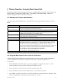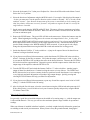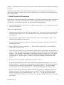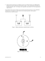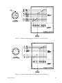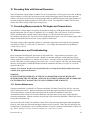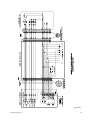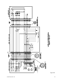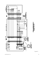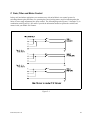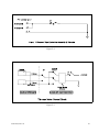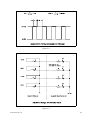
1
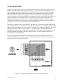
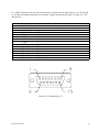
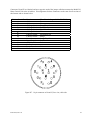
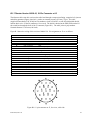
User’s Manual
Model 510 Geodetic Borehole
Tiltmeter and Model 591
Motor Control Unit
Serial No. ____________
Version
90510-01 with cable compression fitting
90510-02 with 16-pin high-pressure connector
90510-03 with 12-pin high-pressure connector
'
'
'
Applied Geomechanics Incorporated
1336 Brommer Street
Santa Cruz, CA 95062 USA
Tel. (831)462-2801, Fax (831)462-4418
[email protected] www.geomechanics.com
Copyright ©1999 Applied Geomechanics Inc. All rights reserved. Manual B-89-1015, Rev. B.
Table of Contents
1 READ THIS FIRST! ...............................................................................................................................................1
2 INTRODUCTION ...................................................................................................................................................1
3 DESCRIPTION OF MODEL 510 TILTMETER SYSTEM................................................................................1
3.1 BOREHOLE TILTMETER ........................................................................................................................................1
3.1.1 Sensing Principle.........................................................................................................................................1
3.1.2 Mechanical Design ......................................................................................................................................5
3.1.3 Electrical Features ......................................................................................................................................5
3.2 SWITCH BOX........................................................................................................................................................6
3.3 MODEL 591 MOTOR CONTROL UNIT ...................................................................................................................6
4 SYSTEM SPECIFICATIONS ..............................................................................................................................12
4.1
4.2
4.3
4.4
TILTMETER PERFORMANCE ...............................................................................................................................12
MOTOR CONTROL UNIT PERFORMANCE ............................................................................................................12
PHYSICAL CHARACTERISTICS ............................................................................................................................13
ENVIRONMENTAL LIMITATIONS .........................................................................................................................13
5 TILTMETER OPERATION: USING THE SWITCH BOX .............................................................................14
5.1 MEANING OF THE CONTROLS AND LOW-BATTERY INDICATOR ..........................................................................14
5.2 TERMINAL STRIP CONNECTIONS ........................................................................................................................14
6 TILTMETER OPERATION: USING THE MOTOR CONTROL UNIT........................................................15
6.1 MEANING OF THE CONTROLS AND INDICATORS .................................................................................................15
6.2 USING THE MOTOR CONTROL UNIT TO LEVEL THE TILT SENSORS.....................................................................15
7 INITIAL CHECK-OUT PROCEDURES............................................................................................................17
8 INSTALLING YOUR TILTMETER IN A BOREHOLE..................................................................................19
8.1 GENERAL CONSIDERATIONS ..............................................................................................................................19
8.2 SHALLOW BOREHOLE PREPARATION .................................................................................................................19
8.3 INSTALLATION PROCEDURE ...............................................................................................................................20
9 GROUNDING AND TRANSIENT PROTECTION...........................................................................................21
9.1 POWER AND SIGNAL GROUNDS (PWR GND AND SIG GND) ............................................................................21
9.2 EARTHING (ESD GND) .....................................................................................................................................22
10 RECORDING DATA WITH EXTERNAL RECORDERS .............................................................................24
11 CONVERTING MEASUREMENTS TO TILT ANGLES AND TEMPERATURES ...................................24
12 MAINTENANCE AND TROUBLESHOOTING .............................................................................................24
12.1 ROUTINE MAINTENANCE .................................................................................................................................24
12.2 CHANGING THE 9-VOLT BATTERY IN THE MOTOR CONTROL UNIT ..................................................................25
12.3 PROBLEMS YOU MIGHT ENCOUNTER ..............................................................................................................25
12.3.1 No Output ................................................................................................................................................25
12.3.2 Output Is Fixed at Limits of Range..........................................................................................................26
12.3.3 Noisy Output ............................................................................................................................................26
12.3.4 Daily and Seasonal Output Fluctuations.................................................................................................26
13 SUMMARY OF CAUTIONS AND WARNINGS.............................................................................................27
14 WARRANTY AND ASSISTANCE....................................................................................................................28
B-89-1015, Rev. B
i
A TILTMETER ASSEMBLY DETAILS ...............................................................................................................29
B CONNECTORS AND WIRING ..........................................................................................................................35
B.1
B.2
B.3
B.4
CONNECTORS COMMON TO ALL VERSIONS.......................................................................................................35
TILTMETER VERSION 90510-01, 19-PIN CONNECTOR AT J3 .............................................................................39
TILTMETER VERSION 90510-02, CONNECTORS AT J3 AND J7 ...........................................................................40
TILTMETER VERSION 90510-03, CONNECTORS AT J3 AND J7 ...........................................................................41
C GAIN, FILTER AND MOTOR CONTROL ......................................................................................................42
D CALIBRATION DATA FOR YOUR TILTMETER.........................................................................................45
List Of Figures
Figure 1. Model 510 Geodetic Borehole Tiltmeter ................................................................................ 2
Figure 2. Model 510 Geodetic Borehole Tiltmeter with Model 591 Motor Control Unit ................ 3
Figure 3a. Electrolytic tilt sensor................................................................................................................. 4
Figure 3b. Electrolevel principles of operation ........................................................................................... 4
Figure 4. Cutaway view of tiltmeter. ........................................................................................................... 7
Figure 5. Detail of sensor leveling mechanism............................................................................................ 8
Figure 6. Closed switch box ........................................................................................................................ 9
Figure 7. Inside of switch box ................................................................................................................... 10
Figure 8. Control panel, Model 591 Motor Control Unit .......................................................................... 11
Figure 9. Battery connections to terminal strip ......................................................................................... 18
Figure 10. Tilt sign convention.................................................................................................................. 18
Figure 11. Recommended tiltmeter installations ....................................................................................... 21
Figure 12. Transient voltage suppressors, 90510-01 ................................................................................. 22
Figure 13. Transient voltage suppressors, 90510-02 .................................................................................. 23
Figure 14. Transient voltage suppressors, 90510-03 .................................................................................. 23
Figure A-1. Model 510 Borehole Tiltmeter upper section ........................................................................ 30
Figure A-2. Model 510 Borehole Tiltmeter lower section ........................................................................ 31
Figure B-1. Model 510 Wiring Diagram, 90510-01 .................................................................................. 32
Figure B-2. Model 510 Wiring Diagram, 90510-02 .................................................................................. 33
Figure B-3. Model 510 Wiring Diagram, 90510-03 .................................................................................. 34
Figure B-4. Pin numbering ........................................................................................................................ 35
Figure B-5. Pin numbering at J1 ................................................................................................................ 36
Figure B-6. Printed Circuit Board Layout - Component Side ................................................................... 37
Figure B-7. 14-pin connector at J4 and J5 ................................................................................................. 38
Figure B-8. 19-pin connector at J3 ............................................................................................................ 39
Figure B-9. 19-pin and 16-pin connectors, 90510-02................................................................................ 40
Figure B-10. 19-pin and 12-pin connectors, 90510-03.............................................................................. 41
Figure C-1. Gain control for Model 510 Tiltmeter.................................................................................... 42
Figure C-2. X and Y channel filter control................................................................................................ 43
Figure C-3. Tiltmeter motor control circuit ............................................................................................... 43
Figure C-4. Motor control timing for Model 510 Tiltmeter ...................................................................... 44
Figure C-5. Adjustment range limit indicator circuit ................................................................................ 44
B-89-1015, Rev. B
ii
1 Read This First!
Your tiltmeter was tested thoroughly before shipment and was in perfect working condition when it left our
factory. To verify that it was not damaged in transit, please perform the initial check-out procedure
explained in Section 7 immediately upon receipt. Also, please familiarize yourself with the maintenance
procedures in Section 12.1 and the cautions and warnings summarized in Section 13 before beginning to use
your tiltmeter. Understanding its basic operating requirements will help ensure that your new tiltmeter
provides many years of trouble-free service.
2 Introduction
Congratulations! You have purchased the most sensitive production tiltmeter in the world today.
The Model 510 Borehole Tiltmeter (Figure 1) is a dual-axis (biaxial) analog output tiltmeter designed for
field applications requiring the ultimate in sensitivity, stability and ruggedness. Applications include
measurement of volcanic and tectonic ground movements, study of earth tides, hydraulic-fracture mapping,
investigation of the material properties of the earth and long-period seismometry.
The same high-precision electronic circuitry and precision electrolytic tilt sensors used in Model 510 are
also found in the Model 520 Platform Tiltmeter. Model 510 contains a remotely controlled sensor leveling
mechanism that allows an operator to null the internal tilt sensors after the tiltmeter has been installed in a
borehole. Model 520 is designed for use on a flat horizontal surface and is manually nulled with its built-in
worm gear or micrometer legs.
Models 510 and Model 520 are part of the Applied Geomechanics family of quality tiltmeters that also
includes the 700 Series, designed for scientific and engineering measurements; the 800 Series, used in civil
engineering and industry; and the low-cost 900 Series designed for a broad range of OEM and end-user
applications.
3 Description of Model 510 Tiltmeter System
Your Model 510 Geodetic Borehole Tiltmeter system consists of three parts: the tiltmeter, the tiltmeter
cable and the switch box (Figure 1). In addition, you probably purchased a Model 591 Motor Control Unit
(Figures 2) which is used for zeroing the X- and Y-axis tilt sensors after the tiltmeter is installed in a
borehole. The Motor Control Unit is the easiest way to operate the internal sensor leveling motors when the
depth of installation is too great for adjusting the tiltmeter position by hand. One Motor Control Unit
services an unlimited number of tiltmeters.
3.1 Borehole Tiltmeter
3.1.1 Sensing Principle
Model 510 senses angular movement with respect to the vertical gravity vector using two electrolytic tilt
sensors. The sensors measure rotations in two orthogonal vertical planes. The vector sum of the rotations in
both planes yields the direction and magnitude of rotation of the tiltmeter.
The sensors in Model 510 can be described as electronic spirit levels (Figure 3a). They operate on the
fundamental principle that a bubble in a liquid-filled case tends to remain stationary with respect to the
B-89-1015, Rev. B
1
vertical gravity vector. As the sensor tilts, the glass case moves around the internal bubble and platinum
electrodes, implanted in the walls of the case (Figure 3b), move into or out of the conductive liquid.
Changes in the electrode area covered by liquid give rise to resistance changes between the excitation and
pick-up electrodes. These changes are proportional to the tilt. The sensors in your tiltmeter operate as AC
potentiometers capable of detecting even the smallest rotational movements. The tiltmeter electronics excite
the sensors with a stable 1 kHz reference voltage, then amplify, rectify and filter the sensor output to form
high-level DC signals proportional to the tilt angle. These signals can be read and recorded by all standard
high-input-impedance recording devices.
Figure 1. Model 510 Geodetic Borehole Tiltmeter, cable and switch box
B-89-1015, Rev. B
2
Figure 2. Model 510 Geodetic Borehole Tiltmeter with Model 591 Motor Control Unit
B-89-1015, Rev. B
3
Figure 3a. Electrolytic tilt sensor
Figure 3b. Sensor design and operation
B-89-1015, Rev. B
4
3.1.2 Mechanical Design
The tiltmeter is divided into two tubular sections: an upper circuit assembly housing and a lower sensor
assembly housing (Figure 4). The upper section of the tiltmeter houses the signal conditioning electronics.
A single printed circuit board occupies most of the length of this section. The lower section contains the
two sensor assemblies and leveling mechanisms. Each sensor is encapsulated in an anodized aluminum
holder, which is part of a sensor leveling mechanism. This mechanism nulls the sensor, then holds it stably
in one position. The two identical mechanisms operate independently of one another (Figure 5).
Each sensor leveling mechanism uses a DC motor to turn a worm gear. The worm gear drives an offset shaft
(cam shaft) that moves a slide that in turn moves the sensor holder. One complete revolution of the cam
shaft causes the sensor holder to rotate through a vertical angle of ±7Ο. Limit switches on the sides of the
sensor holder (Figure 5) turn on an indicator light in the Model 591 Motor Control Unit when the adjustment
range limit is reached. Limit switches are omitted in tiltmeter version 90510-03.
Because a large gear reduction ratio is used, thousands of revolutions of the DC motor are required to move
the sensor holder by a fraction of a degree. This design results in very fine control of the angular position of
the sensors when the tiltmeter is installed in a borehole. It is possible to move each sensor to within 1 or 2
microradians of the desired position using the Model 591 Motor Control Unit.
The two tubular stainless steel housings are joined in the middle by a massive stainless steel center joint
with double O-ring seals on both sides (Figure 4). Double O-rings also seal the top (cable head) and bottom
ends of the tiltmeter.
In version 90510-01 the cable enters the tiltmeter through a compression fitting rated to an external pressure
of 5 bars. In versions 90510-02 and 90510-03 the cable mates with a high-pressure (20,000 psi) connector at
the top end of the tiltmeter. A 19-pin connector joins the cable to the switch box in all three versions of the
tiltmeter.
WARNING: The cable is not designed to support the weight of the tiltmeter. Never pull or lift the
tiltmeter using the cable because damage to the internal electrical connections may result! Always lift
the tiltmeter using the steel handle or support it from below.
3.1.3 Electrical Features
All sensor excitation and signal conditioning is performed on a single printed circuit board inside the
tiltmeter. Putting the signal conditioning circuitry into the tiltmeter next to the sensors reduces the effect of
noise picked up in the cable and results in a high signal-to-noise ratio. It also minimizes thermal effects on
the electronics because they are housed downhole in typically isothermal conditions.
All electrical connections to the tiltmeter, including external power, are made at the switch box. The
tiltmeter cable transfers DC power, gain and filter switching signals, and motor control signals between the
tiltmeter and the switch box. It also conducts the high-level voltage outputs back to the switch box, and
transmits the adjustment range limit signals to the switch box for display on the panel of the Model 591
Motor Control Unit. A wiring diagram for your tiltmeter system is presented in Appendix B.
B-89-1015, Rev. B
5
Other important electrical features of your tiltmeter are:
•
•
•
•
•
All circuit board external connections are gold-plated for long life and noise-free operation.
All resistors are premium quality, 1% tolerance, metal film type or better.
High-quality mylar capacitors are used extensively to achieve electronic stability and minimize
temperature coefficients.
A temperature sensor installed in the printed circuit board provides the basic data needed for evaluation
of thermal effects on the tilt measurements.
Surge absorbers are used on each input and output circuit of the tiltmeter printed circuit board for
protection against electrical transients. High-voltage transients are shorted (conducted) to the steel
tubular body of the tiltmeter, where they are conducted into the ground.
3.2 Switch Box
The switch box (Figures 6 and 7) contains the tiltmeter power switch, gain and filter switches and a lowbattery indicator light. The light illuminates when the positive power supply voltage drops below 11 volts
(see Section 4.1). The gain and filter switches provide control signals to solid-state switches on the printed
circuit assembly inside the tiltmeter. The tiltmeter cable connects to the switch box via the 19-pin connector
in the side of the box (Figure 6). Switch box wiring is shown in Appendix B.
The screw terminal strip in the switch box (Figure 7) provides connections to your external DC power
supply (batteries or AC-to-DC converter) and external data recorders. Access to the terminal strip is via a
feedthrough in the side of the switch box. The feedthrough contains a grommet that can be tightened against
your cable by turning the nut on the outside of the feedthrough. The switch box is equipped with a hasp,
which allows it to be locked for extra security. When the lid is closed, the switch box is protected from light
rain and splashes. It is not waterproof and should never be submerged.
3.3 Model 591 Motor Control Unit
The Motor Control Unit (Figures 2 and 8) is used for leveling the tilt sensors after the tiltmeter has been
installed in a borehole. This unit connects to the switch box via a jumper cable with 14-pin multi-turn
connectors at each end. Digital displays on the Motor Control Unit indicate the outputs of the X and Y tilt
sensors in volts. The control switches are used to operate the motors in the tiltmeter and thereby adjust the
tilt angle of the sensors. With a little practice you should be able to adjust the sensors to within a few
microradians of null every time.
The Motor Control Unit warns you when you approach the end of the sensor's mechanically adjustable
range. Range limit indicator lights turn on when you are near the +7Ο and -7Ο range limits (Figure 8). The
range limit lights are not active in tiltmeter version 90510-03.
Power for the digital displays is provided by a 9-volt battery inside the unit. Power to operate the tiltmeter
motors is obtained from the switch box. Motor control circuitry is presented in Appendix C.
When its lid is closed, your Motor Control Unit is protected from light rain and splashes. It is not
waterproof and should never be submerged.
B-89-1015, Rev. B
6
Figure 4. Cutaway view of tiltmeter
B-89-1015, Rev. B
7
Figure 5. Detail of sensor leveling mechanism
B-89-1015, Rev. B
8
Figure 6. Closed switch box, showing connectors and feedthrough
B-89-1015, Rev. B
9
Figure 7. Inside of switch box, showing control panel
B-89-1015, Rev. B
10
Figure 8. Control panel, Model 591 Motor Control Unit
B-89-1015, Rev. B
11
4 System Specifications
4.1 Tiltmeter Performance
TILT OUTPUT
TILT RESOLUTION
TILT RANGE
OUTPUT VOLTAGE RANGE
TILT SCALE FACTORS
TILT OUTPUT FILTERS
TEMPERATURE COEFS.
OUTPUT IMPEDANCE
TEMPERATURE OUTPUT
POWER REQUIREMENTS
CONNECTIONS
SENSOR LEVELING
Two orthogonal tilt channels. Single-ended and differential analog outputs
proportional to tilt are provided (only differential in version 90510-03).
<10 nanoradians
Approx. ±1400 microradians (µradians) in gain setting “1”
• Approx. ±7 VDC single-ended (±14 VDC differential) in gain setting “1”
• Approx. ±8 VDC single-ended (±16 VDC differential) in gain settings “2” and
“3” (gain “2” omitted in version 90510-02)
• Single-ended: 5, 50 and 500 mV/µradian in gain settings “1”, “2” and “3”
• Differential: 10, 100 and 1000 mV/µradian in gain settings “1”, “2” and “3”.
These scale factors are approximate, see Appendix D for details.
• Two 2-pole Butterworth filters, roll-off = 12 dB/octave (40 dB/decade) above
corner frequency, fC = 1/(2πτ)
• Time constants, τ = 0.1 second (filter “OFF”) and 20 seconds (filter “ON”)
Scale factor: KS = +0.05%/°C typical, Zero: KZ = 2 µradians/°C typical
270 ohms, short circuit and surge protected
10 mV/°C (single-ended), 0 mV = 0°C, −40° to +100°C range, ±0.75°C accuracy.
No temperature output in version 90510-03
• +11 to +15 VDC and −11 to −15 VDC @ +15 mA typical and −7 mA typical;
250 mV peak-to-peak ripple max.
• Reverse polarity and surge protected
• Low battery light on switch plate blinks when positive supply voltage drops
below +11 VDC.
Tiltmeter and switch box connected via 7.5 meter (25 ft) multiconductor cable
(greater lengths available) and 19-pin quarter-turn aluminum connector. Power and
output connections via terminal strip in switch box. See Appendix B for additional
details.
Performed with Model 591 Motor Control Unit. Sensors adjustable through range
of ±7 degrees
4.2 Motor Control Unit Performance
FUNCTION
CONTROLS
DISPLAYS
DISPLAY RANGE
DISPLAY ACCURACY
DISPLAY CHANNELS
CONNECTIONS
POWER
B-89-1015, Rev. B
Model 591 Motor Control Unit adjusts angular position of the X and Y tilt sensors
in Model 510 Borehole Tiltmeter. Digital displays provide quick indication of X
and Y channel outputs.
Power on-off, X-Y motor select, motor forward-reverse, motor pulse width, motor
pulse rate, pulse activate
Dual 3 1/2 digit LCD displays, 12.7 mm (0.5 inch) digit height
+19.99 to -19.99 VDC
0.2 % full scale
X and Y tilt channel outputs
14-pin multi-turn connectors on 3m jumper cable to tiltmeter switch box
+12 volts for operating DC motors in tiltmeter, supplied from switch box. 9-volt
battery behind control panel operates displays. Displays have low-battery
indicators.
12
4.3 Physical Characteristics
SIZE
WEIGHT
MATERIALS
HANDLE
•
•
•
•
•
•
•
•
•
•
•
•
Tiltmeter: 7.6 cm (3 inches) diameter x 122 cm (48 inches) long
Switch Box: 23 x 20 x 14 cm (9 x 8 x 5.5 inches)
Model 591 Motor Control Unit: 28 x 23 x 20 cm (11 x 9 x 8 inches)
Tiltmeter: 22.5 kg (50 lb)
Switch Box: 1.8 kg (4 lb)
Model 591 Motor Control Unit: 2.3 kg (5 lb)
Tiltmeter: Stainless steel tubing and fasteners, anodized aluminum sensor assemblies
(internal), rubber O-ring seals
Cable (P/N 70360): Polyurethane jacket, one overall mylar shield
Switch box: Gray fiberglass
Model 591 Motor Control Unit: Painted aluminum
Version 90510-01 has a stainless steel handle at the cable head.
Versions 90510-02 and 90510-03, designed for deeper installation, have no handle.
4.4 Environmental Limitations
TEMPERATURE
HUMIDITY
DEPTH RATING
•
•
•
•
•
•
•
•
•
•
Tiltmeter and Switch Box: −25° to +70°C operational, −30° to +100°C storage
Neoprene Connector (version 90510-03): −4° to +60°C
Model 591 Motor Control Unit: 0°to +50°C operational,−20° to +70°C storage
Tiltmeter: 0 to 100%
Switch Box: 0 to 100%. Do not allow condensation inside switch box.
Model 591 Motor Control Unit: 0 to 80%. Do not allow condensation on displays or inside
unit.
Version 90510-01: Cable compression fitting rated to 5 bars (72 psi)
Versions 90510-02 & -03: Connector rated to 1400 bars (20,000 psi)
All versions: Case pressure tested to failure at 489 bars (7,090 psi)
Cable selection depends on max. pressure expected
Your Model 510 switch box is protected from light rain and splashes in the field by its cover and rubber
seals. It is not completely waterproof and should never be submerged or exposed to heavy rainfall. Your
Model 591 Motor Control Unit is protected from light rain and splashes by its aluminum cover but is not
sealed against moisture.
CAUTION: Keep the insides of the switch box and Motor Control Unit dry at all times. Water damage to
their internal components voids the warranty!
WARNING: The switch box and the Model 591 Motor Control Unit are not waterproof and should never
be submerged.
B-89-1015, Rev. B
13
5 Tiltmeter Operation: Using the Switch Box
5.1 Meaning of the Controls and Low-Battery Indicator
All of the controls and indicators you will use when operating the Model 510 tiltmeter are in the switch box
(Figure 7) and in the Model 591 Motor Control Unit (Figure 8). The controls inside the switch box have the
following functions:
Control/Indicator
POWER
FILTER
GAIN
LOW BATTERY
Function
When switch is ON, power is supplied to the tiltmeter. In OFF position no power is
supplied. Note: +12 VDC and −12 VDC from an external source must first be connected to
the terminal strip in the switch box. The power switch should be OFF when power is
connected.
Two-position switch selects the time constant of the low-pass filter applied to the output of
the tilt sensors. Section 4.1 gives filter specifications.
Three-position rotary switch controls amplification (gain) applied to the tilt outputs.
Position “1” is lowest gain, setting “3” highest gain. Section 4.1 and Appendix D give scale
factors for each gain setting.
Flashing light indicates when voltage supplied at +12V terminal strip position drops below
+11 VDC. Because (+) power consumption is greater than (−) power consumption, the
positive battery typically is first to fall below the allowable input voltage range.
5.2 Terminal Strip Connections
All power input and signal output connections are made on the terminal strip inside the switch box. To
operate the tiltmeter you simply connect it to the switch box, apply DC power to the terminal strip as
explained below and turn the power switch to “ON”. Functions of the terminals are as follows:
Terminal
X
−X
Y
−Y
TEMP
SIG GND
ESD GND
-12V
PWR GND
+12V
B-89-1015, Rev. B
Function
X tilt channel output. When recording a single-ended value, this signal is referenced to SIG
GND. When recording a differential value, this signal is referenced to −X.
X channel output multiplied by −1
Y tilt channel output. When recording a single-ended value, this signal is referenced to SIG
GND. When recording a differential value, this signal is referenced to −Y.
Y channel output multiplied by −1
Temperature sensor output. This value is a single-ended signal and is referenced to SIG
GND.
Reference ground for the single-ended outputs of the tiltmeter. SIG GND and PWR GND
are common inside the tiltmeter, but not inside the switch box.
This terminal is provided for grounding (earthing) of shield of tiltmeter cable (see Section
9).
Connect −11 to −15 volts DC to this terminal.
Connect the power ground (power common) to this terminal.
Connect +11 to +15 volts DC to this terminal.
14
6 Tiltmeter Operation: Using the Motor Control Unit
The Model 591 Motor Control Unit has two functions: 1. Mechanical adjustment of the X and Y tilt sensors
after the tiltmeter is installed in a borehole and 2. Visual display of the output voltages of the two tilt
channels during quick checks in the field or laboratory.
6.1 Meaning of the Controls and Indicators
All connections, controls and indicators are on the Model 591 control panel (Figure 8) and are described
below:
Control/Indicator
14-PIN CONNECTOR
POWER
AXIS
MOTOR
PULSE
WIDTH
RATE
RANGE LIMIT
X and Y
Function
Connects Motor Control Unit and the tiltmeter switch box
Sensor leveling mechanisms can be operated only when POWER switch is “ON.” 12volt power is supplied from the tiltmeter switch box.
Selects the sensor leveling motor, X or Y, to which power is supplied
Selects direction of tilt adjustment: “forward” or “reverse.” This control was set in the
factory so that tilt output becomes more negative when switch is set for “reverse.”
Output becomes more positive in the “forward” setting.
Activates the selected leveling motor. The LED above the POWER switch flashes as
each voltage pulse is supplied to the motor.
Sets the width, or duration, of the voltage pulse
Sets the frequency of the voltage pulse
These lights illuminate when a sensor leveling mechanism reaches the + or – end of its
adjustment range (Figure 5). If a range limit light goes on while the sensor output is at
the opposite extreme of its voltage range (e.g., + light goes on while output is -8 volts),
you must switch to a lower gain or manually reposition the tiltmeter. Change the
direction of the MOTOR switch immediately when a range limit light goes on. This will
maintain the sensor polarities described under the MOTOR switch definition above.
Version 90510-01: X and Y limit lights operate independently
Version 90510-02: X and Y limit lights operate in common
Version 90510-03: Range limit lights inactive
Digital displays show outputs of the two tilt channels in volts.
6.2 Using the Motor Control Unit to Level the Tilt Sensors
After the tiltmeter has been installed in a prepared borehole (see Section 8) and is within a few degrees of
vertical, use the Motor Control Unit to precisely level the sensors. The following procedure is
recommended:
1. With the POWER switch OFF, connect power to the switch box as explained in Section 5.2. Then
connect the tiltmeter to the switch box and turn the POWER switch ON.
2. Connect the Motor Control Unit to the switch box using the jumper cable.
3. Turn the FILTER switch OFF and the GAIN switch to 1 in the tiltmeter switch box.
4. Turn POWER switch ON in the Motor Control Unit and observe the tilt outputs that are displayed. Both
channels will probably be at their output limits of about +8 or –8 volts.
B-89-1015, Rev. B
15
5. Select the tilt channel (X or Y) that you will adjust first. Move the AXIS switch on the Motor Control
Unit to the X or Y position.
6. Select the direction of adjustment using the MOTOR switch. For example, if the displayed tilt output is
−8 volts, you must move it in the positive direction: set the switch to “forward.” If it is +8 volts, set the
switch to “reverse.” Note: Because the movement of the sensor is controlled by a slowly rotating cam
shaft, this polarity will become reversed (“forward” will produce a negative tilt and vice-versa) if the
range limits are exceeded.
7. Set the motor speed using the WIDTH and RATE dials. The motor will turn at maximum speed when
both are set in the full clockwise direction. When set in the full counter-clockwise direction, the motor
will turn at minimum speed.
8. Depress the PULSE button. The green LED will flash as the motor turns. Release the button to stop the
motor. When beginning the leveling process for a sensor at its output limit of +8 or – 8 volts, a fast
motor speed (WIDTH and RATE dials turned clockwise) can be used. Use a slower speed (WIDTH and
RATE dials turned counter-clockwise) as the output approaches 0 volts. Note that the intensity and
speed of flashes changes as the WIDTH and RATE dials are turned. If you run past 0 volts, simply
change the adjustment direction using the MOTOR switch and continue the leveling process.
9. Switch the tiltmeter GAIN to “2” in the switch box. A jump in tilt output of about 10x should occur.
Continue leveling as described in step 8.
10. If you plan to record filtered tilt measurements, switch the tiltmeter FILTER to ON in the switch box.
Allow 1-2 minutes for the filter to saturate. Verify that the output is still between +8 and –8 volts. If it
is not, turn the FILTER to OFF and adjust the sensor in the desired direction. Then turn the FILTER to
ON and wait until the output stabilizes. Repeat this process until the output remains within the ±8 volt
output range of the amplifiers when the FILTER is ON.
11. Turn the FILTER to OFF and switch the tiltmeter GAIN to “3” in the switch box. Another jump in
output of about 10x should occur. Continue leveling the sensor as in step 8 above. The WIDTH and
RATE dials need to be set in slow (counter-clockwise) positions because the tiltmeter is now running at
a very high gain and small adjustments will produce large output changes. Quickly pressing and
releasing the PULSE button will help you make fine adjustments.
12. If you plan to record filtered tilt measurements, repeat step 10 until the output is near 0 volts in GAIN
setting “3” with the FILTER in the ON setting.
13. After leveling the first tilt sensor, select the second sensor using the AXIS switch and repeat steps 6-12.
With a little practice, you will be able to level your tilt sensors quickly and precisely using the Model
591 Motor Control Unit.
Some Useful Tips About Sensor Leveling:
It is generally a good idea to install the tiltmeter at the middle of its sensing range, i.e., with the output near
0 volts on both channels. This way you will have the maximum dynamic range available for operational
readings.
When your tiltmeter is installed in shallow boreholes, your body weight elastically deforms the ground you
are standing on and can tilt your instrument. When you move away the ground rebounds, changing the
B-89-1015, Rev. B
16
readings. To minimize this effect, try to locate yourself as far from the borehole as possible while adjusting
the sensors.
Mechanical settling of the tiltmeter in the borehole typically occurs over a period of several days or even
weeks after installation. For this reason, the sensors may need to be releveled several times during the early
period of deployment.
7 Initial Check-Out Procedures
Upon receipt of your tiltmeter and before each installation, verify that it is functioning properly by following
the steps below. These steps will familiarize you with its operation and should be performed by everyone
who will use it. To perform this procedure you will need the following equipment:
One (1) Model 591 Motor Control Unit, one (1) digital voltmeter and one (1) ±12-volt DC power source
(or two 12-volt batteries)
CHECK OUT PROCEDURE:
1. Set the bottom of the tiltmeter on a hard, flat, horizontal surface. Use a bubble level placed on top of the
tiltmeter to approximately level it. Secure the tiltmeter to a chair or table using tape or straps to keep it
from falling over.
2. Connect the power supply or batteries to the terminal strip in the switch box (Figures 7 and 9). The
POWER switch should be OFF at this time.
3. Connect the tiltmeter cable to the switch box. Then connect the Motor Control Unit to the switch box
using the jumper cable.
4. Set the GAIN switch on the switch plate to “1”. Set the FILTER switch to OFF. Turn the POWER
switch in the switch box to ON.
5. Locate the X and Y marks at the top of the tiltmeter and familiarize yourself with the sign convention in
Figure 10. Rotate the tiltmeter in the positive and negative X and Y directions while keeping the bottom
stationary. View the output of both channels in the displays of the Motor Control Unit. Verify that the
sign (polarity) of the outputs is as shown in Figure 10 and that the outputs swing to full scale (approx.
±7 volts in gain “1”, ±8 volts in gains “2” and “3”) in the positive and negative directions for each
channel.
6. Repeat the previous step with the GAIN switch in positions “2” and “3”.
7. Verify that the amplification increases as the GAIN switch is advanced from position “1” to “2” to “3”.
With the switch at “1” (lowest gain), level the tiltmeter so that the output is <0.05 volt on both channels.
You may need to use the motor controls to do this. Then switch to GAIN “2”. The output should
increase by about 10x. Then switch to GAIN “3”. The output should increase by about 10x again.
Because of the difficulty of keeping the tiltmeter stationary during this test, the displayed outputs will
not change by exactly 10x and will probably be noisy (variable). Nevertheless, it should be apparent
that they are going up as you switch from setting “1” to “2” to “3”. Turning the filter ON will help
reduce the noise, but you will have to wait 1-2 minutes for the filter to stabilize because of its 20-second
time constant.
B-89-1015, Rev. B
17
8. Finally, check the temperature by touching the probes of your digital voltmeter to the TEMP and SIG
GND positions on the terminal strip in the switch box (Figure 7). The voltage displayed should be the
ambient temperature x 0.01. For example, if the temperature of the tiltmeter is 25°C, the output should
read 0.250 volt.
If your tiltmeter fails to pass any of these tests, first make sure that all connections are secure and that the
terminal strip is receiving power. If these checks do not remedy the problem, contact Applied
Geomechanics for technical assistance.
Figure 9. Battery connections to terminal strip in switch box
Figure 10. Tilt sign convention
B-89-1015, Rev. B
18
8 Installing Your Tiltmeter in a Borehole
8.1 General Considerations
The procedure below describes installation of tiltmeter version 90510-01 in a shallow borehole - shallow
enough that the tiltmeter can be lowered into the hole by hand and coupled to the walls of the hole using
clean sand poured in from above. The maximum practical depth for installation in this manner is typically in
the range of 10-15m. Model 510 tiltmeters, versions 90510-02 and 90510-03, have been installed at depths
greater than 1000m using techniques derived from the oil and gas industry. In these cases the functions of
the Motor Control Unit have been provided by special control systems developed for the project. If you plan
on a deep well installation, please contact Applied Geomechanics for assistance.
Because your Model 510 tiltmeter is so sensitive, it easily detects ground movements caused by cultural
activity (traffic, emptying and filling of tanks, etc.) and environmental changes (temperature, barometric
pressure, rainfall). These effects are attenuated as depth increases, but can have magnitudes of microradians
to tens of microradians in the first 5m below the ground surface. For optimum performance, operate your
tiltmeter in a constant-temperature environment as far as possible from the effects of cultural activity.
Borehole installations should be at least 3 meters deep and preferably deeper. A borehole in an underground
mine or deep tunnel is a very stable operating environment if traffic and other cultural effects are absent.
Before installing the tiltmeter in a borehole it is generally a good idea for the sensor leveling mechanisms to
be in the center of their operating range. To do this, stand the tiltmeter on a flat horizontal surface, such as a
concrete floor, then place a bulls-eye bubble level on the top and move the tiltmeter until the bubble is
centered. Next, with the tiltmeter in GAIN setting “1”, operate the Motor Control Unit (Section 6) until the
X and Y outputs are both within ±1.00 volts. The leveling mechanisms are now centered, which will give
you the maximum adjustment range in the + and − directions after installation.
8.2 Shallow Borehole Preparation
The ideal hole diameter is 20-30 cm (8-12 inches). This diameter allows room for manipulation of the
tiltmeter after it has been lowered to the bottom of the hole. If the ground is dry and the hole will stay open,
casing is not necessary. If caving is a problem, the hole should be cased. In soft ground a steel casing can be
driven to the desired depth using a pile driving machine (Figure 11a).
In hard ground the hole should be drilled with an auger or rotary drill. After drilling, a steel or plastic casing
should be lowered into the hole. The bottom of the casing may be capped or open. If open, the bottom of
the casing can be sealed with concrete after installation to impede water infiltration. The annular space
between the casing and the hole boundary should then be filled with concrete, or with clean, firmly tamped
sand (Figure 11b). Water remaining in the hole should be pumped out or blown out with compressed air
before installation of the tiltmeter. For best results, the hole should remain dry during installation. The sand
will compact and the installation stabilize faster if the sand is dry. Whether the hole is wet or dry, the best
readings are obtained when there is a firm and stable coupling between the tiltmeter, the casing and the
surrounding earth.
Figures 11a and 11b show a larger casing diameter in the upper 1 meter of soil. This optional feature helps
decouple the inner casing from environmentally caused movements in the surface layer. The inner casing
should extend above the bottom of the decoupled zone to keep water and debris from falling into the hole.
B-89-1015, Rev. B
19
8.3 Installation Procedure
The following steps describe installing the tiltmeter into the finished borehole using sand to couple
the tiltmeter to the borehole walls. This procedure uses the tools in Applied Geomechanics Model 729
Borehole Tiltmeter Installation Kit to lower the tiltmeter into the hole, orient its azimuth, pre-level the
tiltmeter and compact the sand in the hole. Additional installation instructions are found in the user’s
manual for the Model 729 kit.
1. Tamp the bottom of the hole to compact any loose dirt using the tamper from the Model 729 tool kit.
Then fill the bottom of the hole with 10-20 cm of fine sand and tamp again.
2. Tie a brightly colored piece of cloth or tape to the +Y side of the tiltmeter handle (Figure 10). Lower
the tiltmeter to the bottom of the hole using a rope or the installation hook from the Model 729 tool kit.
WARNING: Never lower the tiltmeter into the borehole using the tiltmeter cable. Doing so can
damage the internal electrical connections.
3. With the tiltmeter still suspended from the rope or installation hook and in a vertical position, fill the
hole until sand covers the lower half of the tiltmeter. The sand should support the tiltmeter so that it
remains vertical and does not fall over when the rope or tool is removed.
4. Now rotate the tiltmeter about its vertical axis using the installation hook until the azimuth (+Y tilt
direction) has the desired bearing. Record this direction, remove the hook from the tiltmeter and then
from the hole. If you have used a rope instead of the hook, you will not be able to rotate the tiltmeter.
In this case, measure the azimuth of the tiltmeter handle (+Y tilt direction) by looking down the hole and
using a compass. Sunlight reflected from a mirror is a good way to see into the hole.
5. Next, connect ±12-volt power to the switch box, then connect the tiltmeter and the Model 591 Motor
Control Unit to the switch box. Turn the POWER switch ON in the switch box and in the Motor
Control Unit. You are now ready to pre-level the tiltmeter.
6. Pre-level the tiltmeter by gently tamping the sand surrounding it using the tamper or goat’s foot from the
Model 729 tool kit. Read the tilt output on the Motor Control Unit with the GAIN switch in the switch
box in setting “1”. Tamp the sand until the output on both channels is within ±7 volts. Pre-leveling
ensures that the full adjustment range of the sensor leveling mechanisms will be useable after tiltmeter
installation is complete.
7. Fill the hole with sand to the top of the tiltmeter leaving the handle sticking out above the sand. This
way the tiltmeter can be easily extracted from the hole at a later time.
8. Tamp the sand again to compact it while checking the output to be sure the tiltmeter remains roughly
level.
9. You are now ready to begin fine leveling of the tilt sensors using the Motor Control Unit as described in
section 6.
10. When you have completed leveling the tiltmeter, cover the hole for safety.
CAUTION: Always cover the hole after tiltmeter installation. An open hole is dangerous!
B-89-1015, Rev. B
20
(a)
(b)
Figure 11. Recommended Tiltmeter Installations: a. Driven Casing, b. Cemented Casing
9 Grounding and Transient Protection
9.1 Power and Signal Grounds (PWR GND and SIG GND)
Your tiltmeter has separate power ground (PWR GND) and signal ground (SIG GND) wires in the tiltmeter
cable (except version 90510-03). Both are connected (common) inside the tiltmeter. Signal ground is the
reference potential for the single-ended tilt signals (+X, -X,+Y and -Y) and for the temperature signal. We
recommend that you do not connect PWR GND and SIG GND at the switch box or at your power supply or
recorder. Current to power the tiltmeter flows in the power ground wire. From Ohm’s Law we know that
the ground potential will be different at opposite ends of this wire because of wire resistance. By keeping
signal ground separate from power ground, your single-ended tilt and temperature readings will not be
affected by this difference.
B-89-1015, Rev. B
21
9.2 Earthing (ESD GND)
Variable resistance type surge absorbers (transient voltage suppressors) connect several of the wires in the
tiltmeter cable to the stainless steel tiltmeter case (Figures 12, 13 and 14). When the tiltmeter case is in
contact with damp ground, the surge absorbers reduce the likelihood of an electronic failure by shorting
high-voltage transients to earth. High-voltage transients are the most common cause of failure of field
instruments in outdoor installations. In a typical occurrence, a transient from a lightning strike or power
surge travels along the cable until it encounters the instrument’s electronic circuitry, where the delicate lowvoltage components are overloaded and fail. The surge absorbers in your tiltmeter begin to short the
transient to the case and into the earth when the common mode potential difference exceeds 18 volts.
Commercially available surge suppression circuitry may be added at the switch box to provide additional
protection for your tiltmeter. Contact Applied Geomechanics for details.
The shield of the tiltmeter cable (versions 90510-01 and 90510-02) is connected to the ESD GND terminal
in the switch box (Figure 7). The shield is not connected to the tiltmeter case. Earthing the shield may help
suppress transients and reduce noise in your signals. The shield may be earthed by connecting it to a copper
grounding rod with a 16 AWG or heavier copper wire. This may be done at the ESD GND terminal.
Alternatively, the tiltmeter cable shield may be connected to the shield of your power and signal cable at the
ESD GND terminal, then earthed at your power supply location. The shield should be earthed at one
location only to prevent ground loops.
Power ground (PWR GND) is sometimes connected to the cable shield, then earthed to help suppress
transients and reduce noise in the power circuit. Earthing should be done at one location only, typically the
power supply location, to prevent ground loops.
Figure 12. Transient voltage suppressors, Model 510, version 90510-01
B-89-1015, Rev. B
22
Figure 13. Transient voltage suppressors, Model 510, version 90510-02
Figure 14. Transient voltage suppressors, Model 510, version 90510-03
B-89-1015, Rev. B
23
10 Recording Data with External Recorders
The low-impedance voltage outputs of Model 510 can be measured by a wide variety of recorders, including
digital voltmeters, oscilloscopes, strip-chart recorders, digital data loggers and PC-based data acquisition
systems. Follow the instructions for connecting single-ended or differential signals to the input channels of
your data acquisition equipment and you will be ready to record. The amplifiers in Model 510 have been
used to drive cables as long 1500m in previous projects.
11 Converting Measurements to Tilt Angles and Temperatures
Your tiltmeter’s voltage outputs are quickly converted to tilt angles by dividing them by the scale factor of
the gain setting that you are using (see Appendix B). For example, if the scale factor is 50 mV/microradian
(0.050 volt/microradian), and the voltage output reading is +0.300 volt, then the tilt angle is +6.0
microradians from sensor null. Be sure to use the single-ended scale factor if you are recording single-ended
outputs, and the differential scale factor if your outputs are differential.
The output voltage of the temperature channel is converted to temperature by dividing by the temperature
scale factor of 10 mV/°C (0.010 volt/°C) (Section 4.1). For example, the temperature corresponding to
+0.264 volts is +26.4°C.
12 Maintenance and Troubleshooting
Basic maintenance and diagnostic procedures are discussed below. Apart from these procedures, your
Model 510 Tiltmeter is not field-serviceable. Should you encounter problems not described here, please
contact Applied Geomechanics in California for assistance. You may reach us at telephone (831) 462-2801,
fax (831) 462-4418 or email [email protected]. A service engineer will assist you in determining
the cause of the problem, whether the tiltmeter should be returned to the factory for repair, or if it can be
repaired in the field.
Caution: Your tiltmeter should not be opened without first reviewing disassembly/assembly instructions
available from Applied Geomechanics.
WARNING!
IF THE TILTMETER IS OPENED, NEVER USE AN OHMMETER TO MEASURE THE TILT
SENSORS INSIDE THE TILTMETER. APPLYING DC CURRENT THROUGH THE SENSORS WILL
CAUSE PERMANENT DAMAGE THAT IS NOT COVERED BY THE WARRANTY
12.1 Routine Maintenance
If properly maintained, your Model 510 Tiltmeter and Model 591 Motor Control Unit will give you many
years of trouble-free service. Routine maintenance should include regular cleaning of dust, dirt, water and
oil from the tiltmeter, connectors and control panels of the switch box and Motor Control Unit.
Accumulation of dirt or water on electrical connections can cause short circuits, noisy output and other
electronic malfunctions. Whenever possible, keep the lids of the switch box and Motor Control Unit closed
to keep dirt and moisture out.
The closed lids of the switch box and Motor Control Unit will protect them from light rainfall and splashes.
However, these units may leak under prolonged exposure to heavy rainfall. These units will definitely leak
if submerged, so submergence is to be avoided at all times. Keep the switch box and the Motor Control Unit
dry. Water damage to their internal components voids the warranty!
B-89-1015, Rev. B
24
Keep all components away from extremes of heat and cold. Extreme temperatures shorten the life of the
seals and unnecessarily stress the electronic components. Avoid prolonged exposure of the tiltmeter to
direct sunlight on hot days. The stainless steel body is an excellent heat conductor and has a high heat
storage capacity. When left in direct sunlight, internal temperatures can rise high enough to damage internal
components.
If you disassemble the tiltmeter for any reason, make sure that the O-rings and the rubber grommet in the
cable head (version 90510-01) are clean, undamaged and are properly seated during reassembly. A cracked
or broken O-ring can result in leakage of water into the tiltmeter. A light coating of silicon grease or O-ring
lubricant before reassembly will prolong the life of the O-rings and grommet.
When raising and lowering the tiltmeter, always use the steel handle in the cable head or support the
tiltmeter from below. Never lift the tiltmeter by the cable. Lifting by the cable can damage the
internal electrical connections, voiding the warranty!
12.2 Changing the 9-Volt Battery in the Motor Control Unit
The digital displays of the Model 591 Motor Control Unit are powered by one 9-volt battery. When the
output of this battery falls below approximately 7 volts, a low-battery warning will appear in the displays.
Change the battery when this occurs. If the LCD's remain blank when you turn on the Motor Control Unit,
the battery is probably dead and must be replaced. To replace the battery, disconnect the Motor Control
Unit from the switch box and follow the steps below:
1. Remove the eight (8) capscrews that secure the control panel to the case (Figure 8).
2. Gently lift up the front panel, being careful not to pull the wiring.
3. Remove the battery, which is attached to the underside of the front panel.
4. Replace the old battery with a new one.
5. Replace the front panel, and install the 8 screws to secure the front panel to the case.
12.3 Problems You Might Encounter
12.3.1 No Output
Failure to obtain an output signal from the tiltmeter normally is the result of lack of power or a broken wire
or connection. If you have set up your tiltmeter and are getting no output from the X, Y or TEMP channels,
first check that the tiltmeter POWER switch is on and that the Motor Control Unit POWER switch is on. If
these switches are on and there is still no output, check that ±12 VDC power is being supplied to the
terminal strip in the switch box. If there is still no output, check that all connectors are securely attached.
If power is on and all connectors are properly attached, there is probably a bad connection or broken wire in
the Motor Control Unit or its jumper cable, the switch box, the tiltmeter cable or the tiltmeter itself.
Diagnostics should begin with the Motor Control Unit and work toward the tiltmeter. The tiltmeter is the
most complicated part of the system and should not be opened until all other elements of the system have
passed inspection. The wiring diagrams in Appendix B will guide you through your diagnostics.
B-89-1015, Rev. B
25
12.3.2 Output Is Fixed at Limits of Range
In this condition the output stays at the limits of its voltage range (about +8 volts or −8 volts for singleended output, see Section 4.1). The cause is typically that one or both tilt sensors is tilted out of range. This
is especially likely to occur in gain settings “2” and “3”. If the tiltmeter is already installed in a borehole,
switch to GAIN “1” and operate the Motor Control Unit to try to null the output (level the sensor). If the
range limit is reached and the output still has not changed from +8 or −8 volts, you must reposition the
tiltmeter in the hole, or remove it and follow the steps in the next paragraph.
If the tiltmeter is not already installed in a borehole, follow the initial check-out procedures in Section 7 to
verify whether its output will swing to the +8 and −8 volt limits on both the X and Y channels when you
move it. If it does, there is not a problem. However, if the output remains fixed at the limit during this test,
there could be a short circuit to +12V or −12V power somewhere in the wiring, or possibly a broken ground
connection. Inspect the wiring using the wiring diagrams in Appendix B to eliminate this possibility. If the
wiring is found to be in order, the cause may be a bad connection or component inside the tiltmeter. The
tiltmeter must be opened to correct such a problem. Contact the factory for instructions if the problem has
been traced to the circuitry inside the tiltmeter.
12.3.3 Noisy Output
This condition is characterized by output oscillations with amplitudes of tens to thousands of nanoradians.
The oscillations may have periods of less than a second to tens of seconds. Noise of this type is commonly
microseismicity, principally seismic surface waves passing through a shallow tiltmeter installation. The
amplitude of this noise (millivolts) will increase as the gain of the tiltmeter is turned up. Turning the
FILTER switch to the OFF position (Figure 7) should remove most of the microseismic noise in the tiltmeter
output.
Low-frequency ground movements can also be caused by cultural and environmental activity near the
tiltmeter. Examples of such activity are wind blowing through trees, traffic on nearby trails or highways,
animals grazing nearby and burrowing animals. The tiltmeter should be sited to minimize these effects.
Another source of noisy output is bad grounding. Verify that all ground connections are in place to
eliminate this possibility. Earthing the shield of your cable and/or power ground may reduce noise caused
by nearby 50-60 Hz and radio frequency noise sources (Section 9). These wires should be earthed in one
location only. Earthing in more than one location produces ground loops, in which the earth completes a
circuit of current flow through your ground wires. Ground loops always result in undesirable noise and
unpredictable results.
If these checks don’t identify the source of the noise, contact Applied Geomechanics for assistance.
12.3.4 Daily and Seasonal Output Fluctuations
These gradual fluctuations mainly result from ground movement induced by weather and climate changes,
e.g., temperature fluctuations; wetting, drying and freezing of the ground; and changes of barometric
pressure. Daily and seasonal output cycles rarely indicate a problem with your tiltmeter. However, they
can mask the small deformations that you are trying to measure. For this reason, we include this discussion
of their origins and methods for removing them from your data.
Temperature changes affect the tiltmeter in two ways: 1. They produce thermoelastic deformation of the
ground, which is measured by the tiltmeter; and 2. Thermal expansion and contraction of the liquid in the
tilt sensors cause small output changes unrelated to actual ground movement. The latter effect is described
B-89-1015, Rev. B
26
by the tiltmeter’s temperature coefficients (Section 4.1). The most obvious way to eliminate both of these
effects is to install your tiltmeter deeply enough to remove all temperature fluctuations. Temperature
changes and attendant thermoelastic deformations caused by heating and cooling of the ground surface
diminish rapidly with increasing depth. Daily temperature fluctuations are almost zero at a depth of 1 meter.
Annual fluctuations are 90-95 percent attenuated at a depth of 20m. Installations deeper than 20m should
show little effect from temperature.
The temperature sensor inside the tiltmeter measures its temperature. You can remove the effect of
temperature change on the tilt sensors by applying the temperature coefficients of your instrument, as
described in Applied Geomechanics technical note B-95-1005 (available on request). This correction is
performed automatically by our TBASE II Database and Analysis Software. The output fluctuations
remaining after correction for the tiltmeter’s temperature coefficients are the actual ground movements
experienced by the tiltmeter.
Barometric pressure changes produce ground deformation by changing the atmospheric pressure on the
earth’s surface. These changes are not predictable, but can be recognized by comparing barometric pressure
readings to your tilt measurements.
Wetting, drying and freezing of the ground cause near-surface ground deformations. These deformations are
unpredictable but may be recognized by comparing your tilt data to rainfall and surface temperature records.
Because these deformations diminish with depth, the effect is smaller for deeper tiltmeter installations.
13 Summary of Cautions and Warnings
Cautions and warnings have been included throughout this manual to help you keep your tiltmeter system in
peak operating condition. Please review them. Violation of a warning is guaranteed to cause a problem.
Violating a caution may cause a problem and is definitely not recommended. For convenience, the cautions
and warnings given in this manual are summarized below:
Warning: The cable is not designed to support the weight of the tiltmeter. Never pull or lift the
tiltmeter using the cable because damage to the internal electrical connections may result. Always lift
the tiltmeter using the steel handle or support it from below.
Caution: Keep the insides of the switch box and the Model 591 Motor Control Unit dry at all times.
Water damage to their internal components voids the warranty!
Warning: The switch box and the Model 591 Motor Control Unit are not waterproof and should never
be submerged.
Caution: Always cover the hole after tiltmeter installation. An open hole is dangerous!
Caution: Your tiltmeter should not be opened without first reviewing disassembly/assembly instructions
available from Applied Geomechanics.
Warning: If the tiltmeter is opened, NEVER use an ohmmeter to measure the tilt sensors inside the
tiltmeter. Applying DC current through the sensors will cause permanent sensor damage that is not
covered by the warranty!
B-89-1015, Rev. B
27
14 Warranty and Assistance
Standard goods (those listed in Applied Geomechanics’ published sales literature, excluding software)
manufactured by Applied Geomechanics Inc. (AGI) are warranted against defects in materials and
workmanship for twelve (12) months from the date of shipment from AGI's premises with the following
exceptions: Series 900 analog or digital clinometers are warranted against defects in materials and
workmanship for 90 days from the delivery date. AGI will repair or replace (at its option) goods that prove
to be defective during the warranty period provided that they are returned prepaid to AGI and:
a) that the goods were used at all times for the purpose for which they were designed and in accordance
with any instructions given by AGI in respect of them,
b) that notice is received by AGI within 30 days of the defects becoming apparent, and
c) that return authorization is received from AGI prior to the goods being sent back.
Should goods be damaged in transit to the Purchaser, AGI will accept no liability unless the Purchaser can
show that such damage arose solely from AGI's failure to pack the goods properly for shipment.
Software products are warranted to perform substantially in accordance with their documentation for 90
days following your receipt of the software. AGI and its suppliers do not and cannot warrant the
performance or results you may obtain by using the software or its documentation.
In respect of goods or parts thereof manufactured by others and resold by AGI, AGI will pass on to the
customer the benefit of any guarantee or warranty received by AGI from the original manufacturer insofar as
such guarantee or warranty is assignable.
ANY OTHER CONDITIONS OR WARRANTIES WHETHER EXPRESS OR IMPLIED BY STATUTE OR
OTHERWISE ARE EXCLUDED. THE REMEDIES PROVIDED HEREIN ARE THE BUYER'S SOLE AND
EXCLUSIVE REMEDIES. APPLIED GEOMECHANICS INC. SHALL NOT BE LIABLE FOR ANY
DIRECT, INDIRECT, SPECIAL, INCIDENTAL OR CONSEQUENTIAL DAMAGES, INCLUDING LOST
PROFITS OR LOST SAVINGS, WHETHER BASED ON CONTRACT, TORT, OR ANY OTHER LEGAL
THEORY. THIS WARRANTY EXTENDS ONLY TO THE ORIGINAL PURCHASER AND IS EXPRESSLY IN
LIEU OF ALL OTHER WARRANTIES, WHETHER OF MERCHANTABILITY OR FITNESS FOR ANY
PARTICULAR USE, AND OF ALL OTHER OBLIGATIONS AND LIABILITIES OF ANY KIND AND
CHARACTER. THERE ARE NO WARRANTIES WHICH EXTEND BEYOND THE DESCRIPTION ON THE
FACE HEREOF.
a) AGI's liability arising out of the sale of its goods is expressly limited to the repair and/or replacement of
defective parts or the cost of such repair and/or replacement.
b) If software does not perform substantially in accordance with the documentation, the entire and
exclusive liability and remedy shall be limited to either, at AGI’s option, the replacement of the software
or the refund of the license fee you paid for the software.
c) Liability for any other form of loss or damage is hereby expressly excluded.
d) Customer shall indemnify AGI against any third party claim arising out of the use of goods and/or
services supplied by AGI, including any claim arising directly or indirectly out of alleged negligence on
the part of AGI, its employees, servants, representatives or agents.
B-89-1015, Rev. B
28
A Tiltmeter Assembly Details
Figures A-1 and A-2 are exploded views of the upper and lower sections of the tiltmeter. These views show
the principal mechanical components and subassemblies. Caution: Your tiltmeter should not be opened
without first reviewing disassembly/assembly instructions available from Applied Geomechanics, and then
only by an experienced technician.
B-89-1015, Rev. B
29
Figure A-1
B-89-1015, Rev. B
30
Figure A-2
B-89-1015, Rev. B
31
Figure B-1
B-89-1015, Rev. B
32
Figure B-2
B-89-1015, Rev. B
33
Figure B-3
B-89-1015, Rev. B
34
B Connectors and Wiring
Wiring diagrams for the three versions of the Model 510 Geodetic Borehole Tiltmeter are presented in
Figures B-1, B-2 and B-3. Connectors are labeled J1 through J7, P1X and P2Y on the wiring diagrams and
are found at the following locations:
Connector
J1
J2
J3
J4
J5
J6
J7
P1X
P2Y
Location
DB15 subminiature connector on top end of printed circuit assembly inside tiltmeter
In-line connector that joins upper and lower sections of motor control and limit switch wires
inside tiltmeter. Normally replaced by solder splices.
19-pin connectors that joins tiltmeter cable to switch box
14-pin connector that joins switch box to jumper cable
14-pin connector that joins jumper cable to Motor Control Unit, identical to J4
Terminal strip inside switch box
Connector on tiltmeter cable head. Joins tiltmeter to tiltmeter cable (versions 90510-02 and 03 only)
Connects X tilt sensor to printed circuit assembly inside tiltmeter
Connects Y tilt sensor to printed circuit assembly inside tiltmeter
B.1 Connectors Common to All Versions
Pin assignments for connectors J1, P1X and P2Y are the same for all three versions of the tiltmeter and are
described below. The terminal strip (J6) positions are also the same for all versions (see Section 5.2).
P1X and P2Y connect the two tilt sensors (X and Y) in the tiltmeter to the printed circuit assembly (Figures
4, A-1 and B-6). Pin numbering sequence is shown in Figures B-4 and B-6. Pin functions are:
P1X and
P2Y Pin #
1
2
3
Function
(+) Tilt Sensor Excitation
Tilt Sensor Output
(−) Tilt Sensor Excitation
Figure B-4. Pin numbering at P1X and P2Y
B-89-1015, Rev. B
35
J1 is a DB15 connector at the top end of the tiltmeter’s printed circuit assembly (Figures 4, A-1, B-5 and B6). All input and output connections to the tiltmeter’s signal conditioning electronics are made at J1. Pin
functions are:
J1 Pin #
1
2
3
4
5
6
7
8
9
10
11
12
13
14
15
Function
+12 Volts DC
Power Ground
−12 Volts DC
Signal Ground
Temperature
+X Out
+Y Out
−X Out
−Y Out
X Filter Control
X Gain 2 Control
X Gain 3 Control
Y Filter Control
Y Gain 2 Control
Y Gain 3 Control
Wire Color in Tiltmeter Cable (P/N 70360 , version 90510-01 only)
Red
Black
Purple
White/Brown
Yellow
Green
Blue
White/Green Stripe
White/Blue Stripe
White
Gray
White/Gray Stripe
White
Gray
White/Gray Stripe
Figure B-5. Pin numbering at J1
B-89-1015, Rev. B
36
Figure B-6. Model 510 printed circuit assembly, showing location of DB15 connector J1 at end of circuit
board
B-89-1015, Rev. B
37
Connectors J4 and J5 are identical and are at opposite ends of the jumper cable that connects the Model 591
Motor Control Unit to the switch box. Pin assignments for these connectors are the same for all versions of
the tiltmeter and are shown below:
Pin # at J4 and J5
A
B
C
D
E
F
G
H
I
J
K
L
M
N
Function
+X Out
+Y Out
−X Range Limit
+X Range Limit
−Y Range Limit
+Y Range Limit
X Motor Control
Y Motor Control
Motor Return
Signal Ground
+12 Volts DC
Not Used
Power Ground
Not Used
Wire Color in Jumper Cable (P/N 79009)
Green
Blue
Green/White Dot
Red/White Dot
Blue/White Dot
White
Green/Black Dot
Orange
Orange/Black Dot
Red/Black Dot
Red
−
Black
−
Figure B-7. 14-pin connector at J4 and J5, face view, cable side
B-89-1015, Rev. B
38
B.2 Tiltmeter Version 90510-01, 19-Pin Connector at J3
The tiltmeter cable exits this version at the cable head through a compression fitting, comprised of a jam nut
and rubber grommet (Figures 4 and A-1), rated to an external pressure of 5 bars (72 psi). The cable
(Applied Geomechanics P/N 70360) has 20 conductors sized at 24 AWG, overall foil and braided shields,
and one drain wire. Of the 20 conductors, 19 are used. The shield is shorted to the ESD GND terminal in
the switch box through the shell of the J3 connector (Figure B-1). The cable jacket is polyurethane.
Nominal diameter is 10.2 mm (0.40 inch).
Figure B-1 shows the wiring of this version of Model 510. Pin assignments at J3 are as follows:
J3 Pin #
A
B
C
D
E
F
G
H
J
K
L
M
N
P
R
S
T
U
V
Connector Shell
Function
+X Out
−X Out
+Y Out
−Y Out
Gain 2 Control
Gain 3 Control
Filter Control
X Motor Control
Y Motor Control
Motor Return
+X Range Limit
−X Range Limit
+Y Range Limit
−Y Range Limit
−12 Volts DC
Signal Ground
Temperature
+12 Volts DC
Power Ground
ESD Ground
Wire Color in Tiltmeter Cable (P/N 70360)
Green
White/Green Stripe
Blue
White/Blue Stripe
Gray
White/Gray Stripe
White
Orange
Brown
White/Orange Stripe
White/Red Stripe
White/Purple Stripe
White/Yellow Stripe
White/Black Stripe
Purple
White/Brown
Yellow
Red
Black; White with Black & Brown Stripes (2 wires in one pin)
Drain Wire (Cable Shield)
Figure B-8. 19-pin connector at J3, face view, cable side
B-89-1015, Rev. B
39
B.3 Tiltmeter Version 90510-02, Connectors at J3 and J7
This version incorporates a 16-pin stainless steel high-pressure connector (J7) into the tiltmeter cable head.
The tiltmeter cable is detachable. At the opposite end of the cable is the same 19-pin connector (J3) used in
version 90510-01. The table below gives pin assignment for both connectors. The wire colors apply only to
Applied Geomechanics P/N 70360 cable. Figure B-2 is the wiring diagram for this tiltmeter version.
J3 Pin #
A
B
C
D
E
F
G
H
J
K
L
M
N
P
R
S
T
U
V
J7 Pin #
12
13
14
15
Function
+X Out
−X Out
+Y Out
−Y Out
Wire Color in Tiltmeter Cable (P/N 70360 only)
Green
White/Green Stripe
Blue
White/Blue Stripe
6
16
8
9
10
4
1
Gain 3 Control
Filter Control
X Motor Control
Y Motor Control
Motor Return
+X & +Y Range Limit
−X & -Y Range Limit
White/Gray Stripe
Gray
Orange
Brown
White/Orange Stripe
White/Red Stripe
White/Purple Stripe
11
5
2
3
7
Cable Shield (ESD GND)
−12 Volts DC
Signal Ground
Temperature
+12 Volts DC
Power Ground
White/Black Stripe
Purple
White/Brown Stripe
Yellow
Red
Black; White with Black & Brown Stripes (2 wires in one pin)
Figure B-9. (L) 19-pin connector at J3, face view, cable side, (R ) 16-pin connector at J7, face view,
tiltmeter side. Version 90510-02.
B-89-1015, Rev. B
40
B.4 Tiltmeter Version 90510-03, Connectors at J3 and J7
This version incorporates a 12-pin neoprene high-pressure connector (J7) into the tiltmeter cable head. The
tiltmeter cable is detachable. At the opposite end of the cable is the same 19-pin connector (J3) used in
versions 90510-01 and -02. The table below gives pin assignment for both connectors. The wire colors
apply to a standard Subconn 12-conductor SO cable whip. Figure B-3 is the wiring diagram for this
tiltmeter version.
J3 Pin #
A
B
C
D
E
F
H
J
K
R
U
V
J7 Pin #
1
2
3
4
5
6
7
8
9
10
11
12
Function
+X Out
–X Out
+Y Out
–Y Out
Gain 2 Control
Gain 3 Control
X Motor Control
Y Motor Control
Motor Return
–12 VDC
+12 VDC
Power Ground
Wire Color in Subconn SO Whip
Black
White
Red
Green
Orange
Blue
White/Black
Red/Black
Green/Black
Orange/Black
Blue/Black
Black/White
Figure B-10. (L) 19-pin connector at J3, face view, cable side, (R ) 12-pin connector at J7, face view,
tiltmeter side. Version 90510-03.
B-89-1015, Rev. B
41
C Gain, Filter and Motor Control
In deep well and subsea applications our customers may wish to build their own control system for
switching tiltmeter gains and filters, for operating the sensor leveling motors, and for indicating when the
limits of sensor range adjustment have been reached. The following diagrams (Figures C-1 through C-5) in
combination with Figures B-1, B-2 and B-3 provide the information needed to operate the switches and
motors inside your Model 510 tiltmeter.
Figure C-1
B-89-1015, Rev. B
42
Figure C-2
Figure C-3
B-89-1015, Rev. B
43
Figure C-4
Figure C-5
B-89-1015, Rev. B
44
D Calibration Data for Your Tiltmeter
This section presents calibration data and scale factors measured for your tiltmeter on NIST-traceable
calibration equipment at the Applied Geomechanics factory. Calibrations are performed by rotating the
tiltmeter in each of its principal planes (X and Y) over a range of at least 11 known angles and measuring
its output. Each scale factor reported for GAIN settings “1” and “2” is the slope of a linear
regression line over the full calibration range. Nonlinearity is the maximum deviation of any
point from the regression line, expressed as percentage of full span (±1000 microradians angular
range = 2000 microradians span, etc.). The scale factor for gain setting “3” is established by
multiplying the scale factor for gain setting “2” by the gain ratio between settings “3” and “2.”
Scale factors for single-ended and differential outputs are both reported (see Section 5.2 for
explanation).
B-89-1015, Rev. B
45
Single-Ended Scale Factors
Model 510 Geodetic Borehole Tiltmeter
Channel
(X or Y)
Gain
(1, 2 or 3)
B-89-1015, Rev. B
Calibration
Range (µradians)
Serial No.
Calibration
Temp. (oC)
Scale Factor
(mV/µradians)
Scale Factor
(µradians/mV)
Nonlinearity
(% of FS)
46
Differential Scale Factors
Model 510 Geodetic Borehole Tiltmeter
Channel
(X or Y)
Gain
(1, 2 or 3)
B-89-1015, Rev. B
Calibration
Range (µradians)
Serial No.
Calibration
Temp. (oC)
Scale Factor
(mV/µradians)
Scale Factor
(µradians/mV)
Nonlinearity
(% of FS)
47
ANGLE CONVERSION CHART
degrees
arc minutes
arc seconds µradians
mm/meter
inches/ft
1
60
3600
17453
17.5
0.209
arc minutes =
0.0167
1
60
291
0.291
3.46E
arc seconds =
2.78E
0.017
1
4.85
4.85E
5.82E
µradians =
5.73E
3.44E
0.206
1
0.001
1.20E
mm/meter =
0.057
3.436
206.2
1000
1
0.012
inches/ft =
4.785
286.5
17182
83333
83.33
1
degrees =
B-89-1015, Rev. B
-4
-3
-3
-3
-3
-5
-5
48