1
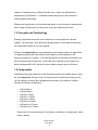
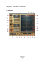
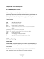
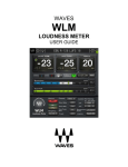
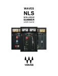
WAVES InPhase USER GUIDE Table of Contents Chapter 1 – Introduction.................................................................................................... 3 1.1 Welcome.................................................................................................................. 3 1.2 Product Overview .................................................................................................... 3 1.3 Concepts and Terminology...................................................................................... 4 1.4 Components ............................................................................................................ 4 Chapter 2 – Quick Start Guide .......................................................................................... 5 Chapter 3 – Interface and Controls ................................................................................... 6 3.1 Interface................................................................................................................... 6 3.2 Controls ...................................................................................................................7 Chapter 4 – The WaveSystem ........................................................................................ 11 4.1 The WaveSystem Toolbar ..................................................................................... 11 4.2 Preset Handling ..................................................................................................... 11 4.3 Interface Controls .................................................................................................. 14 4.4 Waves Preferences (Pro Tools only)..................................................................... 16 Appendix – Routing and Usage Examples...................................................................... 17 Waves InPhase User Guide 2 Chapter 1 – Introduction 1.1 Welcome Thank you for choosing Waves. In order to get the most out of your Waves processor, please take the time to read through this manual. In conjunction, we also suggest you become familiar with www.wavesupport.net. There you will find an extensive Answer Base, the latest Tech Specs, detailed Installation guides, new Software Updates, and current information on Authorization and Registration. By signing up at www.wavesupport.net, you will receive personalized information on your registered products, reminders when updates are available, and information on your authorization status. 1.2 Product Overview InPhase is an innovative, easy-to-use plugin that corrects phasing issues between tracks. Phasing can occur throughout the production process: In recording, when multiple signals are combined: Like individual drum mics and overheads; guitar amps and DIs; and sources recorded with more than one microphone. In mixing, when phasing issues that weren’t addressed during recording need to be corrected. In mastering, when the final stereo mix has phasing problems. To help you restore phase coherence, InPhase features high resolution dual waveform displays; phase shift filters with adjustable frequency and Q; and an intuitive correlation meter which shows you just how much your tracks are in—or out of phase. You can move your waveforms manually or using the delay control, and even align them in Waves InPhase User Guide 3 relation to a sidechain input. InPhase includes mono, stereo, and dedicated live components, plus InPhase LT, a simplified version that gives you easy access to creative phase manipulation. Phasing can cause drops in volume and wreak havoc on your frequency response and stereo image; InPhase gives you the power to get your tracks back on track. 1.3 Concepts and Terminology Phasing is a phenomenon which occurs when two or more signals are summed together. For this reason, when discussing phasing issues, we are always referring to the relationship between two or more signals. InPhase uses allpass filters to correct phasing issues between tracks. An allpass filter is a signal processing filter that affects only the phase, not the amplitude of the frequency-response of a signal.. A 1st order allpass filter is defined by the frequency at which the phase shift is exactly 90°; a 2nd order filter is defined by the frequency at which the phase shift is 180° and by the rate of phase change, hence its Q factor. 1.4 Components WaveShell technology enables us to split Waves processors into smaller plugins, which we call components. Having a choice of components for a particular processor gives you the flexibility to choose the configuration best suited to your material. InPhase includes the following components: o o o o o o o o InPhase Mono InPhase Stereo InPhase LT Mono InPhase LT Stereo InPhase Live Mono InPhase Live Stereo InPhase Live LT Mono InPhase Live LT Stereo Please note: All components have 20 ms latency, excluding Live components, which have no latency. Waves InPhase User Guide 4 Chapter 2 – Quick Start Guide There are three basic ways to work with InPhase: 1. Using InPhase to correct the phase relation between two mono tracks. 2. Using InPhase to correct the phase relation between the left and right channels of a stereo track. 3. Using InPhase to align a stereo track to a sidechain reference. Detailed examples for each of the above scenarios are provided in the Appendix section of this manual. We recommend that you read through them in order to gain a basic understanding of the InPhase workflow. Video demonstrations of these examples are also available at www.waves.com. Additionally, the InPhase LT components may be used for creative phase manipulation. Waves InPhase User Guide 5 Chapter 3 – Interface and Controls 3.1 Interface Waves InPhase User Guide 6 3.2 Controls 1. Processing Sections InPhase has two processing sections: In Stereo components, they are called Alpha and Beta; in Mono components, Alpha and SC. 2. Process Controls In Stereo components, the Alpha and Beta Process controls let us choose what to process. When CH1 is selected in the Alpha section, it will force CH2 to the Beta section. This setup is recommended for stereo tracks or dual mono tracks such as bass amp and bass DI. In Stereo components, when CH1/2 is selected in the Alpha section, the sidechain input is forced to the Beta section. This setup is recommended when processing signals in relation to a signal routed to the plugin via sidechain. In Mono components, the audio is forced to the Alpha section and the sidechain input is forced to the Beta section. This setup is recommended when processing signals in relation to a signal routed to the plugin via sidechain. Please note: In Logic and ProTools HD (TDM Mixer), sidechain functionality is not supported due to delay compensation and timing issues. 3. Activity LED shows when there is input signal activity. 4. Gain controls the level of the signal going into the processing section. 5. Phase Invert flips the phase by 180 degrees. 6. Phase Shift Curve Window displays the phase shift curve across the frequency line, and updates in real time as parameters change. Waves InPhase User Guide 7 7. Type sets the phase shift filter type, and toggles between Off, Shelf (using the 1st order allpass filter) and Bell (using the 2nd order allpass filter.) 8. Frequency selects the frequency at which the phase shift is 90° using the 1st order (Shelf) allpass filter or 180° using the 2nd order (Bell) allpass filter. 9. Q sets the width of the 2nd order (Bell) allpass filter: A narrower Q results in a faster phase transition toward the selected frequency, leaving a larger portion of the frequency intact. 10. Delay lets us move the signal up to 20 milliseconds in either direction. (Live components forward only.) We recommend adjusting the pure delay before adding any phase shift to the process. 11. Monitor selects the output monitor configuration. o When Stereo Mix is selected, the Alpha and Beta section signals, in stereo, are monitored. (When CH1/2 in relation to SC is selected, monitored output signal is attenuated by 6 dB to compensate for the level increase caused by track summing.) o When Mono Mix is selected, the Alpha and Beta/SC section signals, summed to mono, are monitored. (Monitored output signal is attenuated by 6 dB to compensate for the level increase caused by summing to mono.) o When Alpha is selected, the Alpha section signal only is monitored. o When Beta/SC is selected, the Beta section signal only is monitored. 12. Output LED displays the peak signal output level. 13. Collapse closes the waveform display section. Waves InPhase User Guide 8 14. Capture has two modes, Automatic & Manual, which capture up to two seconds of signal at 44.1/48 kHz or one second at 88.2/96 kHz. o Automatic – When you click Capture, the mechanism will wait for a signal peak above -40 dBFS. When the first peak exceeds -40 dBFS, it will automatically capture the next one or two seconds (depending on the sample rate), and then stop. o Manual – Click Capture to begin capturing, and click it again to stop. In both modes, Capture time is limited to one or two seconds, depending on sample rate. 15. Scroll Bar scrolls the x axis of the captured waveform. 16. Correlation Meter displays the general correlation value metering between the captured Alpha and Beta waveforms, at the output of the delay and phase processing applied. The values move between 1 and -1; the higher the value, the better the correlation. 0 indicates no correlation between the signals. 1 indicates maximum correlation (identical signals). -1 means the signals are completely out of phase. 17. Correlation Markers display the maximum value of the correlation meter. Blue represents peak correlation value; orange represents negative peak value. If the negative correlation exceeds the positive, try flipping the phase on one of the sections. 18. Correlation Value Box displays the current correlation value, and updates in real time. 19. Zoom X zooms in on the x axis, at up to sample resolution. Waves InPhase User Guide 9 20. Reset Zoom resets the zoom to its default setting. 21. Zoom Y Beta zooms in on the Beta section y (amplitude) axis. 22. Beta Waveform is the waveform captured in the Beta section. 23. Zoom Y Link links Zoom Y Alpha and Zoom Y Beta. 24. Zoom Y Alpha zooms in on the Alpha section y (amplitude) axis. 25. Waveform Displays show the captured waveforms. The display updates in real time according to the processing applied, excluding gain changes. 26. Marker sets the center position for the zoom. Scrolling doesn’t change the marker position and, in certain situations, will place it outside the visible area. The marker also helps us align the peaks of the waveforms. Holding Alt/Option will help you move the Marker when the curser is on the waveform display. 27. Copy Alpha Beta copies the plugin settings to the InPhase clipboard. to easly move settings between stereo and mono components. 28. Paste Alpha pastes the settings of the Alpha section from the InPhase clipboard. It is possible to paste the Alpha settings to the same plugin instance or to any other open InPhase plugin instance. 29. Paste Beta pastes the settings of the Beta section from the InPhase clipboard. In the mono component, settings are pasted to the Alpha section. It is possible to paste the Beta settings to the same plugin instance or to any other open InPhase plugin instance. Waves InPhase User Guide 10 Chapter 4 – The WaveSystem 4.1 The WaveSystem Toolbar All Waves plugins feature the WaveSystem toolbar which takes care of most administrative functions you will encounter while working with your Waves software. The features of the WaveSystem toolbar are the same on practically all Waves plugins, so familiarity with its features will be helpful whichever plugin you are using. Toolbar Functions Opens the plugin About box Undo Undoes the last 32 actions Redo Redoes the last 32 undone actions Setup A/B Toggles between two presets, useful for comparison of parameter settings L/R Arrows Move to the previous or next preset Copy A→B Copies the current settings to the second preset register Load Recalls presets from file Save Saves presets in the Waves file formats ? Opens the PDF manual for the plugin you are using 4.2 Preset Handling Preset Types Factory Presets are permanent presets in the Load menu. Factory presets cannot be overwritten or deleted. When applicable, different component plugins may have different factory presets. User Presets are your favorite settings of the plugin saved as a preset in the Load menu, under ‘User Presets’. User Presets can be overwritten and deleted. Waves InPhase User Guide 11 Setup Files may contain more than one preset. For example, a single file can contain all the presets for a session. When you open a Setup File, all its setups become part of your Load pop-up menu for fast access. This can be particularly useful with multiple instances of a plugin in a single session. By saving all the settings you create into a single Setup File, they can all be quickly available for every instance of that plugin. Loading Presets and Setups Click on the Load button to see the Load pop-up menu. The menu is divided into four sections. If a section is not currently available it will not appear in the Load pop-up menu. Open Preset File… Select to open any setup or preset file, whether from the Library or your own creations. ‘Filename.xps’: Displays any currently loaded Setup File and its presets. Factory Presets: Displays the default Factory Presets. User Presets: Displays any loaded User Presets. Saving Presets and Setups Click on the Save button to see the Save pop-up menu. Four options are available. If an option is not currently available it will be grayed out and inaccessible. Save to New File… Select this to start a new Setup file. There are two prompts - first for the setup filename, then for the preset name. You must provide a name for both the setup file and the preset. Click OK (ENTER) to complete the save. It is a good idea to create a folder in which to save several setup files for a project. Save ‘File Name’ – “Preset Name” Overwrites the settings of the loaded preset (whether a User Preset or a preset from a Setup File) with the current settings. If a Setup File is Waves InPhase User Guide 12 currently loaded, the name of the Setup File is displayed followed by the name of the preset itself. If a User Preset is loaded, its name is displayed. Save to ‘File Name’ As… Saves the current settings as a new preset into the Setup file that is open (if one is not open, the option is grayed out). You will be prompted to give the preset a name. Put into Preset Menu As… Save the current settings into a User Preset that will always be in your Load menu (until deleted). You will be prompted to give this preset a name. User Presets are stored in the plugin’s preference file. Deleting Presets You may delete User Presets and presets within a Setup File. Factory Presets and Setup Library files cannot be deleted or overwritten. 1. Hold the Command (Mac)/Control (PC) key down. 2. Click-and-hold the Load button to see the pop-up menu. 3. While still holding the Command/Control key, select the preset or setup to delete. 4. A confirmation box will appear, allowing you to cancel or ‘OK’ the deletion. A/B Comparison and Copying The Setup A/Setup B button may be clicked to compare two settings. If you load a preset in the Setup B position, this will not affect the preset loaded into the Setup A position, and vice-versa. If you want to slightly modify the settings in Setup A, you can copy them to Setup B by clicking on the Copy to B button, then alter Setup A and compare with the original Setup B. Waves InPhase User Guide 13 The name of the current setup will be shown in the title bar (on platforms which support it), and will switch as you change from Setup A to Setup B. Note: an asterisk will be added to the preset name when a change is made to the preset. 4.3 Interface Controls Controls can be in one of three states: 1. Not Selected where the control is not the target of any user entry 2. Selected where the control is the target of mouse control entry only 3. Selected and Active where the control is the target for both mouse and keyboard entry Toggle Buttons Toggle buttons display the state of a control, and allow switching between two or more states. Single-click to change the control’s state. Some toggle buttons have a text display which updates with the current setting, and others (bypass, solo, or monitoring toggles) illuminate when the control is active. Some plugins have link buttons between a pair of toggle buttons, allowing click-anddrag adjustment while retaining the offset between the controls. Value Window Buttons Value windows display the value of a control and allow click-and-drag adjustment, or direct control via the keyboard. Using the mouse, click-and-drag on the value window to adjust. Some value windows support left/right, some up/down (as you hover over a button, arrows will appear to let you know which direction of movement that button supports). You may also use your mouse-wheel to adjust parameter values. Using the arrow keys, click once with mouse to select the button, and then use up/down – left/right (depending on the direction supported by that button) to move in the smallest incremental steps across the button’s range (holding down Waves InPhase User Guide 14 the arrow keys will move faster through the range). Using key entry, double click on the button to open the value window, and directly enter the value from your keyboard. If you enter an out of range number, the button stays selected but remains at the current setting. (System beeps if system sounds are on.) Some plugins have link buttons between a pair of value windows, allowing click-anddrag adjustment while retaining the offset between the controls. Sliders Click or scroll the mouse-wheel on the slider itself or anywhere within the sliders track. The numerical value of the slider settings is displayed in a hover window above the slider path. Hover Box Hovering boxes will appear and display the control value when hovering with the mouse over the control. Multiple Control Selection One of the most powerful features of the WaveSystem is the ability to select and adjust multiple controls simultaneously. Using the mouse, drag-select the desired group of buttons or graphic controls by clicking and holding at a point outside the controls, and forming a rectangle that includes the controls you wish to adjust. Alternatively, press and hold Shift while clicking the mouse on any control you wish to link. This method is useful when you want to select two or more controls that are not adjacent to one another. Waves InPhase User Guide 15 TAB Functions TAB moves the ‘selected’ status to the next control, with shift-TAB moving in the reverse direction. Additionally, the Mac has an option-TAB function for ‘down’ movement and shift-optionTAB for ‘up’ movement where applicable. If you have several Value Window Buttons selected, TAB functions will take you through the selected controls only. Hitting Esc or Return will return the 'focus' to the DAW application. 4.4 Waves Preferences (Pro Tools only) When launching Pro Tools, hold Shift to view the Waves plugin Preferences window. The following options are available: Don't use AudioSuite plugins Don’t use RTAS plugins Rescan all plugins HUI control surface support (low resolution) Enable single-click text entry Waves InPhase User Guide 16 Appendix – Routing and Usage Examples All examples are made using Pro Tools. Example 1 – Aligning Two Mono Tracks Using Sidechain This example uses two tracks, bass amp and bass DI. Open the InPhase Mono component on the bass amp track Send the bass DI track to Bus 1 Assign the InPhase sidechain key input to receive from Bus 1. Click Capture and play a short loop. Once the capture is complete, you’ll see the bass amp waveform in the Alpha section display and bass DI in the Sidechain (SC) section display. In the monitor section, click Mono Mix to monitor both tracks summed to mono. On the Waves System Bar, click Copy A>B to toggle between A, the processed signal, and B, the unprocessed signal. Set the marker to the beginning of a note with a clear start point. Zoom in to get a good look at the note’s first transient, which will be our sync point. Set the marker to the zero cross point of the bass DI track in the SC section. Use the Alpha section delay control to align the zero crossing of the Alpha waveform to the SC section, or grab the waveform to move it manually. Look at the correlation meter and make sure you’re on the blue, positive side of the meter. Play back your loop and, using the A-B setup, toggle between the processed and unprocessed signals to make sure track alignment has improved. If you experience energy loss in a certain frequency range a result of the delay adjustment, turn on the first phase shift filter by clicking on the Shelf or Bell toggle, then sweep to find the spot where the desired frequency returns. Toggle between A and B to make sure the summing of the two tracks is improved. If needed, adjust a second frequency range using the second phase shift filter. Toggle between A and B to hear the improvement. Waves InPhase User Guide 17 Example 2 – Aligning Two Mono Tracks Routing to a Stereo Aux This example uses two tracks, bass amp and bass DI. Open an Aux track and assign Bus 1-2 as its input. Set the output of the bass amp to Bus 1 and the output of the bass DI to Bus 2. Open the InPhase Stereo component on the Aux. Click Capture and play a short loop. Once the capture is complete, you’ll see the bass amp waveform in the Alpha section display and bass DI in the Beta section display. In the monitor section, click Mono Mix to monitor both tracks summed to mono. On the Waves System Bar, click Copy A>B to toggle between A, the processed signal, and B, the unprocessed signal. Set the marker to the beginning of a note with a clear start point. Zoom in to get a good look at the note’s first transient, which will be our sync point. Set the marker to the zero cross point of the bass DI track in the Beta section. Use the Alpha section delay control to align the zero crossing of the Alpha waveform to the Beta section, or grab the waveform to move it manually. Look at the correlation meter and make sure you’re on the blue, positive side of the meter. Play back your loop and, using the A-B setup, toggle between the processed and unprocessed signals to make sure track alignment has improved. If you experience energy loss in a certain frequency range a result of the delay adjustment, turn on the first phase shift filter by clicking on the Shelf or Bell toggle, then sweep to find the spot where the desired frequency returns. Toggle between A and B to make sure the summing of the two tracks is improved. If needed, adjust a second frequency range using the second phase shift filter. Toggle between A and B to hear the improvement. Copy the settings to the Waves clipboard by clicking Copy Alpha, Beta on the Waves System Bar. Waves InPhase User Guide 18 Open the InPhase Mono component on the bass amp track. Click Paste Alpha on the Waves System Bar to paste the Alpha section settings from the clipboard. Assign the bass amp and DI outputs back to the main mix outputs. Example 3 – Aligning a Stereo Track This example uses a stereo piano track. Open the InPhase Stereo component on your stereo track. In the process pull down menu of the Alpha section select CH1, which will force CH2 to the Beta section. Click capture and play a short loop. Once the capture is complete, you’ll see the left channel of the stereo piano waveform in the Alpha display and the right channel in the Beta display. On the Waves System Bar, click Copy A>B to toggle between A, the processed signal, and B, the unprocessed signal. Set the marker to the beginning of a note with a clear start point. Zoom in to get a good look at the note’s first transient, which will be our sync point. You’ll see that the Alpha waveform is early compared to the Beta, so we will adjust the Beta waveform to match the Alpha. Set the marker to the zero cross point of the Alpha track. Use the Beta section delay control to align the zero crossing of the Beta section to the Alpha section, or grab the waveform and move it manually. Look at the correlation meter and make sure you’re on the blue, positive side of the meter. Play back your loop and, using the A-B setup, toggle between the processed and unprocessed signals to make sure track alignment has improved. If you experience energy loss in a certain frequency range a result of the delay adjustment, turn on the first phase shift filter by clicking on the Shelf or Bell toggle, then sweep to find the spot where the desired frequency returns. Waves InPhase User Guide 19 Toggle between A and B to make sure the summing of the two tracks is improved. If needed, adjust a second frequency range using the second phase shift filter, in this case around 120 Hz. Toggle between A and B to hear the improvement. Example 4 – Aligning a Stereo Track to a Sidechain Offline This example uses an overheads tracks which we will align to the snare top track. Find a short overheads loop which contains a snare hit. From the offline menu(AudioSuite), select InPhase Stereo. Set the InPhase sidechain key input to receive from the snare top track. In the Alpha section process pull down menu, select CH1/2, which will force the SideCh to the Beta section. On the Waves System Bar, click Copy A>B to toggle between A, the processed signal, and B, the unprocessed signal. Click capture and play the loop you selected. Set the marker to the beginning of a snare hit. Zoom in to get a good look at the note’s first transient, which will be our sync point. Set the marker to the peak point of the first transient on the snare track in the Beta section. Grab the waveform and move it manually, or use the Alpha section delay control to align the zero crossing of the Alpha section to the Beta section. Look at the correlation meter and make sure the value has improved toward the blue, positive side of the meter. Play back your loop and, using the A-B setup, toggle between the processed and unprocessed signals to make sure track alignment has improved. If you hear that some of the snare’s body has disappeared, turn on the first phase shift filter, select the bell shape with a narrow Q setting, and sweep to find a spot that brings back the missing frequencies. Toggle between A and B to make sure the summing of the two tracks is improved. Waves InPhase User Guide 20 To bring back any mids/high mids that have also disappeared, turn on the second phase shift filter and sweep to find a spot that brings back the missing frequencies. Toggle between A and B to hear the improvement. The snare now has more snap and punch. Now all we need to do is process the track. Waves InPhase User Guide 21