1
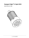
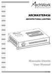
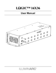
LΩGIC™ 16X36
Quick Reference Guide
LΩGIC™ 16X36 QRG
About this
Guide
The LΩGIC ™ 16X36 Quick Reference Guide (QRG) only contains the
product’s connection and mounting information, as well as the menu
options and the DMX values.
Disclaimer
This QRG does not replace the product’s User Manual. You must
download the corresponding User Manual from the ILUMINARC®
Web site (www.iluminarc.com) to learn about the disclaimers, safety
notes, programming modes, and technical information.
·
Safety Notes
·
·
·
·
·
·
·
·
·
DO NOT open this product unless instructed. It contains no user
serviceable parts.
DO NOT look at the light source when the LΩGIC™ products are
on.
DO NOT touch the LΩGIC™ controller or products while
operating because they may be hot.
DO NOT cover the ventilation slots when this product is operating
to avoid internal overheating.
DO NOT leave any flammable material within 50 cm from the
LΩGIC™ controller or products while connected to the power
outlet to minimize the risk of fire.
DO NOT mount this product overhead without using a safety
cable.
DO NOT operate this product or any LΩGIC™ product in any
location where dust, excessive heat, water, or humidity may affect
them.
DO NOT operate this product or any LΩGIC™ product if you see
damage on the housing, lenses, or cables. In such case, have the
damaged parts replaced by an authorized technician at once.
DO NOT connect this product to a dimmer or rheostat.
ONLY connect this product to a grounded and protected circuit.
What Is · One LΩGIC™ 16X36
Included · One RJ-45 to 3-pin DMX male adapter (input)
·
·
·
·
One RJ-45 to 3-pin DMX female adapter (output)
Sixteen (16) RJ-45 couplers
One Warranty Card
One Quick Reference Guide
2
LΩGIC™ 16X36 QRG
Features 1, 2, 3, 4, 6, 9, or 48-channel DMX control
Operating modes:
1-channel: RGB, dimmer (no individual RGB adjustments)
3-channel: RGB control (individual RGB adjustments)
4-channel: RGB control, dimmer
6-channel: RGB control, dimmer, color macro, strobe
9-channel: RGB control, dimmer, color macro, strobe, auto
+ custom, auto speed, zone selection
48-channel: RGB control, line control
· 16 output lines
· RGB color mixing with or without DMX control
· Automated and customizable programs
· Recall auto and custom programs via master/slave or DMX
Additional Features
·
·
·
·
·
Master/Slave (RJ-45)
Static Playing
RGB and white color calibration
Schedule playback with time clock functions
LCD display with password protection
·
3
LΩGIC™ 16X36 QRG
AC Power
The LΩGIC™ 16X36 has an auto-ranging power supply that can work
with an input voltage range of 100~240 VAC, 50/60 Hz.
Make sure that you are connecting this product to the proper voltage, as
per the specifications in this guide, the product’s User Manual, or on the
product’s sticker.
AC Plug
The LΩGIC™ 16X36 comes with a power input cord that enters
through a strain relief boot that is then hardwired to the inside of the
unit. The other end of the power cord is bare-ended. Please use the table
below to wire the new plug.
Connection
Wire (US)
AC Live
Black
Screw Color
(US)
Wire
(Europe)
Yellow or
Brown
Brass
AC Neutral
White
Silver or Gray
Blue
AC Ground Green/Yellow
Green
Green/Yellow
Fuse
Replacement
1) Disconnect the product from the power outlet.
2) With a Phillips #2 head screwdriver, unscrew the fuse holder cap from
its housing.
3) Remove the blown fuse and replace it with a good fuse of the same type
and rating (F 10 A, 250 V).
4) Screw the fuse holder cap back in its place and reconnect power.
4
LΩGIC™ 16X36 QRG
Mounting
Before mounting this product, read the safety notes at the beginning of
the LΩGIC™ 16X36 User Manual and follow the mounting procedures
indicated in it.
The LΩGIC™ 16X36 consists of a single unit with 4 mounting points.
ILUMINARC® recommends following the general guidelines below
when mounting the LΩGIC™ 16X36.
When selecting an installation location, consider ease of access to the
unit for operation, programming adjustments, and routine
maintenance.
Never mount the unit in places where rain, high humidity, extreme
temperature changes, or restricted ventilation may affect it.
Make sure that the location where you are mounting the unit can support
its weight. Please see the Technical Specifications section of the
User Manual for the weight requirement of this unit.
Use four screws to attach the unit to a flat, dry surface. Make sure that
you can access the unit for maintenance and programming.
5
LΩGIC™ 16X36 QRG
CAT5 Linking
The LΩGIC™ 16X36 controller uses a signal patch implemented with a
CAT5/6 cable to link to other LΩGIC™ 16X36 controllers (see Cable
Connections).
To use this product in Master/Slave mode, you must connect the master
and slave LΩGIC™ 16X36 controller using the CAT5 link.
DMX Linking
Each LΩGIC™ 16X36 controller comes with a pair of RJ-45 to XLR 3
adapters for connection to a DMX universe (DMX controller and other
DMX products linked with a DMX connection). See Cable Connections
for a detailed pin out diagram.
LΩGIC™
Fixture
Connectivity
Each LΩGIC™ product comes with a CAT5 cable to link it to the
LΩGIC™ 16X36 controller. You can connect the product directly to
any of the 16 output lines of the LΩGIC™ 16X36 controller, or you
could make an extension to install the LΩGIC™ product at a farther
location.
In this case, you can use an RJ-45 coupler or an RJ-45 splitter to
connect the LΩGIC™ product to the extension cable. See Fixture
Connection Diagram for more details.
Splitter
Each LΩGIC™ product comes with an RJ-45 splitter to allow the
connection of two products to a single LED output port of the
LΩGIC™ 16X36 controller. You can use more than one splitter on a
single LED output as long as you respect the maximum load of 36
LEDs (12 LEDs per color). See Maximum Output Line Loading for
more details.
RJ-45
Terminator
To make an RJ-45 terminator, connect 120 ohms, ¼ W resistor between
pins 6 (green/white) and 7 (white/brown) of an RJ-45 plug.
Insert the terminator into the DMX Out RJ-45 jack of the last LΩGIC™
16X36 controller, as shown in Product Connection Diagram.
6
LΩGIC™ 16X36 QRG
Cable
Connections
DMX to RJ-45 adapter: Used to link a DMX controller to the LΩGIC™ 16X36
RJ-45 Plug
DMX XLR (male)
RJ-45 Plug Pin Assignment
View facing pins
XLR (male)
3-pin
RJ-45 Plug
Pin 1: Not Used
Pin 2: Not Used
Pin 3: Not Used
Pin 4: Not Used
Pin 5: +5 V
Pin 6: Data +
Pin 7: Data Pin 8: GND
XLR (male)
5-pin
3-pin XLR Male
5-pin XLR Male
Pin 3: Data +
Pin 2: Data Pin 1: GND
Pin 4: Not Used
Pin 5: Not Used
Pin 3: Data +
Pin 2: Data Pin 1: GND
Signal Patch cable: Used for linking two LΩGIC™ 16X36 controllers
RJ-45 Plug
RJ-45 Plug
Pin 1: Not Used
Pin 2: Not Used
Pin 3: Not Used
Pin 4: Not Used
Pin 5: +5 V
Pin 6: Data +
Pin 7: Data Pin 8: GND
Pin 1: Not Used
Pin 2: Not Used
Pin 3: Not Used
Pin 4: Not Used
Pin 5: +5 V
Pin 6: Data +
Pin 7: Data Pin 8: GND
LED Patch Cable: Used to link the LΩGIC™ 16X36 controller to its products.
Pin #
Wire Color
1
2
3
4
5
6
7
8
White/Orange
Orange/White
White/Green
Blue/White
White/Blue
Green/White
White/Brown
Brown/White
7
Function
Red LED +
Green LED +
Blue LED +
Not Used
Red LED Green LED Blue LED Not Used
LΩGIC™ 16X36 QRG
RJ-45 to DMX adapter
(Included with controller)
Product
Connection
Diagram
Connect the DMX
controller to the first
LΩGIC™ 16X36 using
a DMX to RJ-45 adapter
cable.
Link each LΩGIC™
16X36 with a RJ-45
signal patch cable, as
shown. You can use a
RJ-45 coupler to link
the LED patch and the
product’s CAT5 cable.
LED
patch
RJ-45 Coupler
(Included with controller)
Signal
patch
RJ-45 Terminator
You should use an RJ45 terminator on the
DMX output of the last
LΩGIC™ 16X36.
Once done, connect
your lights (loads)
directly to the
corresponding line
outputs.
Alternatively, you can
use the line splitter
connector(s), as seen in
the diagram.
RJ-45 Splitter
(Included with
product)
Do not use the splitter as a coupler. All cables must be terminated to a
product.
8
LΩGIC™ 16X36 QRG
Fixture
Internals
To understand the maximum load allowed per output line, it is
important to know how the internal components are wired inside the
LΩGIC™ products.
LEDs and Dies
Single color LEDs have a single die (the part of the LED that generates
light). Tri-color LEDs have three dies (one for each color) on a single
package.
LEDs and
Clusters
·
·
Inside the LΩGIC™ products, the LEDs are grouped in clusters of three
LED dies each.
In a product with single color LEDs, three individual LEDs compose the
cluster.
In a product with tri-color LEDs, a single tri-color LED makes up the
cluster.
LEDs Wiring
In an LED cluster, each LED die connects to an individual output
channel from the LΩGIC™ controller. When a product has more than
one cluster, all the LED dies of a particular color connect to the same
output channel.
Maximum
Output Line
Loading
The LΩGIC™ 16X36 controller has 16 output lines. You can select
each output line individually or you can select all output lines (Zone
Selection).
Each output line has three channels: Red, Green, and Blue.
Each of the three output channels can support up to 12 LED dies.
Therefore, the maximum number of LED dies supported per output line
is 36.
When connecting LΩGIC™ products to the LΩGIC™ 16X36 controller, do
not exceed the maximum of 12 LED dies per output channel (36 LEDs
dies per output line).
The table below shows the maximum number of LΩGIC™ products
that can be loaded onto an output line per product model.
Model Name
Total Total LED
LEDs
Dies
Max. Fixtures
per Output
Ilumiline LΩGIC™ 24 RGB
24
24
1
Ilumiline LΩGIC™ 24 Optic RGB
24
24
1
Ilumiline LΩGIC™ 12 Optic RGB
12
12
3
Ilumipod LΩGIC™ 12 Optic RGB
12
12
3
Ilumipod LΩGIC™ 6 Optic RGB
6
6
6
Ilumipod LΩGIC™ 3 Optic RGB
3
3
12
Ilumipod LΩGIC™ Tri-1 RGB
1
3
12
Ilumipod LΩGIC™ Tri-4 RGB
4
12
3
9
LΩGIC™ 16X36 QRG
RGB Mode Menu Options
Main
1. Play auto
Programming Steps
RGB 1~10
RGBL 1~10
4. Play schedule
5. DMX address
6. Personality
7. Edit custom
1~255
SPEED
RED
GREEN
LALL
STATIC
L-1~16
BLUE
PLAYING
(Output Line) DIMMER
STROBE
SCHEDULE PLAYING!
001~512
EFFECT
RGB
RGB+D
RGB+DMS
RGB+LINE
RGB+LINE+DMS
SOLID
R
G
B
C-1~10
S-1~20
S
(Custom)
(Scene)
T
F
0~255
Play scheduled program
Sets DMX starting address
9-channel mode
3-channel mode
4-channel mode
6-channel mode
48-channel mode
51-channel mode
1-channel mode
0~255
0~20
0~255
ALLOW EDIT
RESET ALL
RESET CUSTOM
RESET SCHEDULE
UPLOAD
YES/NO
PASSWORD? [Enter Password]
8. Settings
TIME NOW
CLOCK
EDIT TIME
DOW
DAY
MONTH
YEAR
HOUR
MIN
SEC
Combine Red, Green, and Blue to
generate a custom color
Set the strobe frequency
Set the on time
Set the fading time
Turn password protection on after
30 seconds of being idle
Enable/disable Custom program
editing
Default all settings
Erase the custom programs
Erase the schedule
Transfer custom programs from
master to slave units
View the current DOW, date, and
time.
SU~SA
01~31
01~12
00~99 Edit the DOW, date, and time
00~23
00~59
Continues on the next page
10
Configure and/or play a single step
program per output line
0~20
ON/OFF
PASSWORD
Choose from 20 automatic
programs
Choose from 10 user-defined
programs
CUSTOM 1~10
2. Play custom
3. Play static
Instructions
LΩGIC™ 16X36 QRG
Continued from previous page
Main
Programming Steps
WHITE 1~9
R
G
B
CALIBRATION
RGB TO WHITE
Instructions
0~255
8. Settings
(Cont.)
YES/NO
RGB TO WHITE
DMX
SLAVE
EASY PLAY
9. Operation
SUNDAY~SATURDAY
(Different schedules for
each DOW)
10. Schedule
11. Patch
EVERYDAY
(Same schedule for
every DOW)
PATCH 1~6
RGB
RGBL
No. [1~10] CUSTOM
1~10
STATIC
PLAY NONE
RGB
RGBL
CUSTOM
11
1~10
Modify the White macros (RGB
mode)
Configure RGB to WHITE
values
[Yes] RGB TO WHITE defines
output color when RGB faders are
at “255”
[No] Max. intensity when RGB
faders are at “255”
Work with a DMX controller
Slave mode
Optional remote
After selecting DOW, schedule #,
and program, enter starting and
ending time [00:00~23:59]
Used with optional controller
LΩGIC™ 16X36 QRG
RGB Mode DMX Values
EFFECT
Channel Function
1
2
3
4
Red
Step Time
Green
Step Time
Blue
Dimmer
5
Color Macro +
White Balance
6
Strobe
7
Auto + Custom
Programs
8
Auto Programs
Speed
Value
000 ó 255
000 ó 255
000 ó 255
000 ó 255
000 ó 010
011 ó 035
036 ó 060
061 ó 085
086 ó 110
111 ó 135
136 ó 160
161 ó 185
186 ó 210
211 ó 215
216 ó 220
221 ó 225
226 ó 230
231 ó 235
236 ó 240
241 ó 245
246 ó 250
251 ó 255
000 ó 004
005 ó 255
000 ó 020
021 ó 030
031 ó 040
041 ó 050
051 ó 060
061 ó 070
071 ó 080
081 ó 090
091 ó 100
101 ó 110
111 ó 120
121 ó 130
131 ó 140
141 ó 150
151 ó 160
161 ó 170
171 ó 180
181 ó 190
191 ó 200
201 ó 210
211 ó 220
221 ó 255
Percent/Setting
0~100%
When CUS. 01-10 in CH. 7 is activated
0~100%
When CUS. 01-10 in CH. 7 is activated
0~100%
0~100%
No Function
R: 100% G: Up
B: 0%
R: Down G: 100% B: 0%
R: 0%
G: 100% B: Up
R: 0%
G: Down B: 100%
R: Up
G: 0%
B: 100%
R: 100% G: 0%
B: Down
R: 100% G: Up
B: Up
R: Down G: Down B: 100%
White 1: 3,200 K
White 2: 3,400 K
White 3: 4,200 K
White 4: 4,900 K
White 5: 5,600 K
White 6: 5,900 K
White 7: 6,500 K
White 8: 7,200 K
White 9: 8,500 K
No Function
0~20 Hz
No function
Auto RGB 1
Auto RGB 2
Auto RGB 3
Auto RGB 4
Auto RGB 5
Auto RGBL 1
Auto RGBL 2
Auto RGBL 3
Auto RGBL 4
Auto RGBL 5
Custom 1
Custom 2
Custom 3
Custom 4
Custom 5
Custom 6
Custom 7
Custom 8
Custom 9
Custom 10
No function
000 ó 255 Slow~fast
Continues on the next page
12
LΩGIC™ 16X36 QRG
Continued from previous page
DMX Mode
(Cont.)
Channel Function
9
RGB
RGB+D
RGB+DMS
Zone Selection
Channel Function
Value
000 ó 009
010 ó 029
030 ó 049
050 ó 069
070 ó 089
090 ó 109
110 ó 129
130 ó 149
150 ó 169
170 ó 189
190 ó 199
200 ó 209
210 ó 219
220 ó 229
230 ó 239
240 ó 249
250 ó 255
Value
Percent/Setting
All Lines
Line 1
Line 2
Line 3
Line 4
Line 5
Line 6
Line 7
Line 8
Line 9
Line 10
Line 11
Line 12
Line 13
Line 14
Line 15
Line 16
Percent/Setting
1
Red
000 ó 255 0~100%
2
Green
000 ó 255 0~100%
3
Blue
000 ó 255 0~100%
Channel Function
Value
Percent/Setting
1
Red
000 ó 255 0~100%
2
Green
000 ó 255 0~100%
3
Blue
000 ó 255 0~100%
4
Dimmer
000 ó 255 0~100%
Channel Function
Value
Percent/Setting
1
Red
000 ó 255 0~100%
2
Green
000 ó 255 0~100%
3
Blue
000 ó 255 0~100%
4
Dimmer
000 ó 255 0~100%
Color Macro +
White Balance
000 ó 010
011 ó 035
036 ó 060
061 ó 085
086 ó 110
111 ó 135
136 ó 160
161 ó 185
186 ó 210
5
No Function
R: 100% G: Up
R: Down G: 100%
R: 0%
G: 100%
R: 0%
G: Down
R: Up
G: 0%
R: 100% G: 0%
R: 100% G: Up
R: Down G: Down
Continues on the next page
13
B: 0%
B: 0%
B: Up
B: 100%
B: 100%
B: Down
B: Up
B: 100%
LΩGIC™ 16X36 QRG
Continued from previous page
RGB+DMS
(Cont.)
RGB+LINE
SOLID
Channel Function
Value
Percent/Setting
5
Color Macro +
White Balance
(Cont.)
211 ó 215
216 ó 220
221 ó 225
226 ó 230
231 ó 235
236 ó 240
241 ó 245
246 ó 250
251 ó 255
6
Strobe
000 ó 004 No Function
005 ó 255 0~20 Hz
Channel Function
Value
White 1:
White 2:
White 3:
White 4:
White 5:
White 6:
White 7:
White 8:
White 9:
Percent/Setting
1
Red #1
000 ó 255 0~100%
2
Green #1
000 ó 255 0~100%
3
Blue #1
000 ó 255 0~100%
46
Red #16
000 ó 255 0~100%
47
Green #16
000 ó 255 0~100%
48
Blue #16
000 ó 255 0~100%
Channel Function
1
Master Dimmer
Value
Percent/Setting
000 ó 255 0~100%
Continues on the next page
14
3,200 K
3,400 K
4,200 K
4,900 K
5,600 K
5,900 K
6,500 K
7,200 K
8,500 K
LΩGIC™ 16X36 QRG
Button
<MENU>
Control Panel
Description
<ENTER>
<UP>
<DOWN>
Programming 1.
Notes
2.
3.
1.
2.
3.
Function
Exits from the current menu or function
Enables the currently displayed menu or sets the currently
selected value into the selected function
Navigates upwards through the menu list and increases the
numeric value when in a function
Navigates downwards through the menu list and decreases
the numeric value when in a function
Press <MENU> repeatedly until WELCOME appears on the top line
of the display. This is the top of the menu map.
Press <MENU> repeatedly until finding the desired Main level option
for the current mode.
Press <ENTER> to access the Main level function currently displayed.
What appears on the bottom line of the display is one of the choices for
the current option.
Use <UP> and <DOWN> to navigate the menu map and menu options.
Press <ENTER> to access the menu option currently displayed or to
enable a select value.
To return to the previous option or menu without changing the value,
press <MENU>.
For details on how to program the LΩGIC™ 16X36 controller, download
the corresponding User Manual from www.iluminarc.com.
15
LΩGIC™ 16X36 QRG
Contact Us
General Information
World Wide Web
LΩGIC™ 16X36 QRG – Rev. 04
© Copyright 2013 ILUMINARC®
All rights reserved.
Printed in the P. R. C.
16
ILUMINARC®
5200 NW 108th Avenue
Sunrise, FL 33351
Voice: (954) 923-3680
Fax:
(954) 929-5560
(ATTN: ILUMINARC®)
www.iluminarc.com