Download LB0009-02GB
Transcript
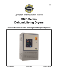
SMD10
SMD11
SMD15
SMD30
Step Motor Drivers
User Manual
JVL Industri Elektronik A/S - January 1992
LB0009-02GB
Revision 11th Feb 98
Contents
1.1
Introduction
2
1.2
Overview of Driver Models
3
1.3
Front and Rear Panels
4
1.4
Power Supply
7
1.5
Adjustment of Motor Phase Current
1.6
Connection of Step Motor
10
1.7
Motor Step Resolution
12
1.8
Inputs and Outputs
13
1.9
Step Pulse and Direction Inputs
14
1.10
CW/CCW Limit Inputs
15
1.11
Stop Input
16
1.12
Status and Error Outputs
17
1.13
Step Pulse and Direction Outputs
18
1.14
Overview of Driver Connections
19
2.1
Step Generator
21
2.2
Adjustment of Motor Parameters
24
3.1
Physical Dimensions
26
3.2
Electrical Specifications
29
3.3
Electrical timming
31
3.4
Motor Connections
32
3.5
Overview of Switch Settings
33
1
8
1.1
Introduction
Types SMD10, SMD11, SMD15 and SMD30 are a
series of step motor drivers which meet almost every
requirement for precise control of step motors.
The Drivers can be used for controlling a wide range
of step motors, supplying phase currents of up to 12
Amp/phase and voltages in the range 12 to 150V.
The following Driver models are available:
- Basic drivers equipped with inputs for step-pulse
and direction signals,
- Drivers with an integral step generator which enables trimmer potentiometers to be used for adjusting the motor start rate, acceleration/deceleration
rate, and additionally enable two different top rates
to be used in the same motor operation.
- A Driver model built into an EMR suppression cabinet with an integral 230 V power supply.
The Drivers are based on the "Bipolar chopper" principle, which provides approximately 40% greater
motor torque over a large range of speeds than
commonly used "Unipolar chopper" drivers.
The Drivers are equipped with a total of 7 inputs and
4 outputs, all of which are optically isolated from
other Driver circuitry.
Two of the inputs are used for end-of-travel inputs
which stop motor operation instantaneously when
activated. Two analogue inputs enable the motor
current and Top Rate to be controlled using an externally applied voltage. DIP Switches on the front
panel of the Drivers are used to set different configurations, enabling inputs to be defined for various
purposes depending on the actual application.
For example the function of inputs can be defined so
that if one input is activated the motor advances, if
another input is activated the motor reverses. Alternatively, one input may be used to start the motor,
another to stop the motor.
A third input can be used to select one of the two defined motor Top Rates.
Features:
• Only a single supply voltage required.
• External operating frequency 0-20kHz.
• Internal operating frequency 0-10kHz.
• Bipolar chopper driver (0-12A/phase).
"A" version 3 Amp.
"B" version 6 Amp.
"C" version 12 Amp.
• Facility for controlling motor Top Rate via external voltage (0-5 / 0-10V).
• Facility for controlling motor phase current via
external voltage 0-5 V.
• Stop Input which stops motor operation immediately the input is activated.
• Status Output which indicates whether the motor
is stopped or running.
• CW (Clockwise) and CCW (Counter Clockwise)
end-of-travel inputs.
• All inputs and outputs optically isolated.
• All inputs and outputs handle 5-30VDC.
• Facility for 2 motor speeds during same operation.
• Torque of up to 12 Nm at 300 rev/min.
• Overload protection. Motor output short-circuit
protected.
• Eurocard dimensions 160x100x47 [mm].
With integral power supply 160x112x103 [mm].
SMD11/30 171x111x138 [mm].
• Mounting either in 19"-rack or via T-groove.
• Connection
via
DIN
socket,
(optional).
• Option: Mains-supply 115 V AC.
2
or
terminals
1.2
Overview of Driver Models
See Section 3.1 for Physical Dimensions
All models include the following features:
-
Adjustment of motor Standby Current.
Adjustment of motor Operating Current.
End-of-travel, CW/CCW Limit Inputs.
External adjustment of motor current.
External switching between Standby Cur-rent
and Operating Current.
LED indication of motor operation.
Stop Input.
Status Output for motor operation.
Error Output.
Step Pulse Output.
-
3
Direction Output.
Short-circuit protection of motor output.
Voltage Output 5V DC/50mA.
Full- and Half Step modes of operation.
All digital inputs and outputs optically isolated.
Automatic switching between Operating and
Standby Current.
Overvoltage protected.
1.3
Front and Rear Panels
Front Panel :
Adjustment of Motor Operating and Standby Current
Indication of Overload
"Power" Indicator
Error Indicator
Motor Operating Indicator
Adjustment of System Parameters
Adjustment of Motor Start Rate, Top Rate
and Acceleration
(models with built-in Step Generator only)
Rear Panel :
Connector: DIN41612/Ver. D
Supply 12-45V/15-80V
Status Output
Analogue Input for Control of Motor Current
Analogue Input for Control of Speed
Motor Output
Stop Input
CW/CCW Limit Inputs
Control Inputs
Chassis (ground)
4
(SMD10/15_1 / SMD10/15_2 only)
1.3
Front and Rear Panels
5
(SMD10/15_3 / SMD10/15_4 only)
1.3
Front and Rear Panels
6
(Types SMD11xx only)
1.4
Power Supply
ensure that the supply voltage is maintained in the
range 12-15V, even if a mains voltage drop occurs.
Supply (Drivers without Integral Power Supply).
To ensure that powering the Drivers is as simple as
possible, models which do not include an integral
mains power supply are powered from a single
supply voltage. The internal circuitry ensures the
correct voltages for the motor output driver, control
circuits. etc.
In the event that the supply is connected with incorrect polarity or an overload occurs, the Drivers are
fuse-protected. In such cases, the Driver should be
disconnected from the supply and the fuse replaced. It is recommended that the external supply
used to power the Driver is equipped with a capacitance of min. 2000-5000µF connected across
the positive (P+) and negative (P-) terminals. It is
also recommended that 0.75mm² cables (min.) are
used to connect the Driver to the supply. If the
Driver supply voltage falls below 10V, the Driver will
be reset. Precautions should therefore be taken to
Supply (Drivers with Integral Power Supply).
Types SMDxxx3 and SMDxxx4 are equipped with
an integral power supply for direct connection to a
230V AC mains supply.
The Driver's internal supply voltage is available via
an external terminal and can thus be used for supplying other Drivers included in the motion control
system.
If a mains overload occurs, the Driver's overload
protection circuitry will be activated and either the
primary or secondary fuse will be blown. If an
overload occurs, the Driver should be disconnected
from the mains supply and the fuse replaced.
The Driver's primary and secondary fuse holders
are located below the mains supply connector (see
above illustration).
7
1.5
Adjustment of Motor Phase Current
The Standby and Operating current supplied to
1. Either by allowing the Driver to control the cur-
each of the step motor's phases can be adjusted
rent supply. This is done by setting the Current
using 2 potentiometers on the front panel of the
Selection DIP switch to Internal (see above il-
Driver.
lustration).
Typically the motor phase current should be ad-
switches between Standby Current and Oper-
justed to provide a significantly higher operating
ating Current when the motor is started or
current, since the motor requires greater power to
stopped.
overcome its inertia during acceleration and con-
The
Driver
then
automatically
2. Or by controlling the motor current via an exter-
stant speed.
nal control signal. This is done by setting the
The operating current can either be adjusted using
Current Selection DIP
the potentiometer or controlled via an externally
Switching between motor Standby Current and
applied voltage (see following page).
Operating current is then determined by the
Switching between Standby Current and Operating
signal applied to the C.Sel (Current Select) In-
Current is achieved in the following way:
put. If this Input is set to logic "0", the preset
switch
to
External.
Standby Current is selected. If the Input is logic
"1", the preset Operating Current is selected.
8
1.5
Adjustment of Motor Phase Current
To control the value of the motor phase current us-
If the DIP is set to Internal, the Operating Current is
ing an external control signal, the Driver's C.Adj
determined by the setting of the trimmer potenti-
(Current Adjust) Input can be used.
ometer on the Driver front panel.
The C.Adj Input is used to apply an analogue con-
To control the Input using a signal in the range 0-
trol voltage in the range 0-5V DC corresponding to
20mA, a 250 Ohm resistor should be connected
a motor phase current of 0 to 3A for Driver Types
between A.GND (Analogue Ground) and the C.Adj
SMDxxAx, 0 to 6A for Types SMDxxBx, and 0 to
Input.
12A for Types SMDxxCx.
A 5V Out Output is also provided which supplies a
Note that the C.Adj. Input can only be used as an
voltage of 5V DC. This output is used if it is re-
alternative to the trimmer potentiometer for adjust-
quired to connect a potentiometer to the C.Adj In-
ing the motor Operating Current. Internal or exter-
put. It is recommended that the 5V Out output is
nal control of the Operating Current is selected us-
used if only one power supply is available and is
ing the Current Adjustment DIP switch (see above
being used for other purposes and therefore a po-
illustration).
tential source of noise.
If the DIP switch is set to External, the C.Adj Input is
used for adjusting the motor Operating Current.
9
1.6
Connection of Step Motor
Various types of Step Motor are available:
Serial Connection:
Note: Type 3 motors above (Unipolar) are not
suited for operation with JVL Drivers since the Drivers use the Bipolar principle. Bipolar systems typically provide 40% greater torque than unipolar
systems.
2-phase and 4-phase step motors can be connected to the Drivers as follows:
Using serial connection of the phases, a motor provides the same performance (up to 1kHz) as parallel connection, but using only approximately half
the current. This can influence the selection of
Driver type, enabling a Driver rated for a lower motor current to be used. See above illustration.
If the phases of a 4-phase motor are connected in
serial, the motor's rated current should be divided
by 1.41. For example, if the rated current is 4.2A,
the maximum setting of the Driver current trimmer
potentiometers must not exceed 3A when the
phases are connected in serial.
2-Phase Motors (4 cables).
Parallel Connection.
This type of step motor can be directly connected to
the Driver's output. The Driver current adjustment
must not exceed the specified rated current for the
motor.
With parallel connection of motor phases, a motor
will provide better performance at frequencies
above 1kHz compared to serially connected
phases, but requires approximately twice the current. This can influence the choice of Driver since it
is necessary to select a Driver which can supply
twice the current used for a serial phase configuration. See above illustration. When the phases of a
4-phase motor are connected in parallel, the specified rated current of the motor must be multiplied by
a factor of 1.41. For example, if the rated current is
4.2A, the maximum setting of the Driver current
trimmer potentiometer must not exceed 5.9A when
the phases are connected in parallel.
1. 2-phase Bipolar (4 cables)
2. 4-phase Bipolar/Unipolar (8 cables)
3. 4-phase Unipolar (6 cables). Not suitable.
4-Phase Motors (8 cables).
This type of step motor can be connected to the
Drivers in the two following ways:
1. Serial connection of phases.
2. Parallel connection of phases.
Selection of serial- or parallel connection is typically
determined by the speed requirements of the actual
system.
If slow speeds are required (typically less than
1kHz), the motor phases can be connected in serial. For operation at higher speeds (greater than 1
kHz), the motor phases can be connected in parallel.
10
1.6
Connection of Step Motor
It should be noted that the lower the self-inductance
Cabling.
of a step motor the better, since this influences the
For Driver models which supply a phase current in
torque at high speeds. The torque is proportional to
the range 0 to 6A, it is recommended that 0.75mm²
the current supplied to the motor as follows:
cable (minimum) is used to connect the motor to
the Driver.
Current ~
~ Torque
~
~
Applied Voltage
For Driver models which supply a phase current of
Phase Induction x Frequency
0 to 12A, it is recommended that 1.5mm² cable
(minimum) is used.
The applied voltage is regulated by the Driver so
that the phase current is adjusted to the selected
Cable lengths used to connect the motor to the
value.
Driver should not exceed 10 metres because of im-
In practice this implies that if a motor with a large
pedance loss.
self-inductance (e.g. 100mH) is used, the Driver
cannot supply the required phase current at high
Important !
speeds (high rotational frequencies) since the out-
To minimise noise interference from the motor ca-
put voltage is limited.
bles, screened cable should be used to connect the
Driver to the motor. If screened cables are not
used, electronic interference of other equipment in
the system can occur.
11
1.7
Motor Step Resolution
The Driver can be configured for either Full- or Half
Overload Protection
Step motor operation. The driver type SMD15 can
The Drivers are short-circuit protected. If the peak
additionally be set to the resolutions 1/4 step or 1/8
current exceeds the Driver's maximum current by
step. Often it can be an advantage to operate with
+20% for a period greater than 2ms, the output
higher step resolutions than half step since each
voltage to the motor is disconnected. An instanta-
motor revolution is divided into smaller and more
neous short-circuit of any two output terminals will
precise steps. This often eliminates the need for
not damage the Driver; the Overload LED (see
mechanical gearing.
above illustration) will simply indicate that an overload has occurred. The supply voltage to the Driver
Another significant advantage of 1/4 or 1/8 Step
must then be disconnected for a period of 5 sec-
operation is that the motor resonance which may
onds to reset the Driver.
be encountered with Full-Step operation can normally be avoided. The resonance frequency of a
Note: ! The Driver is not protected against short-
step motor depends on the applied load and results
circuits to ground (P-).
in complete loss of torque.
For large motors, the resonance frequency will
normally be outwith the normal operating range (the
frequencies in which the motor is accelerated or
decelerated).
Configuration of the Driver for Full- or Half Step operation is set using the Step Mode DIP switch as
shown in the above illustration:
12
1.8
Inputs and Outputs
Overview of Digital Inputs and Outputs
SMDxxxx
I/O+
Load
Status
Max. 50mA
CLK OUT
DIR OUT
ERROR
Sensor
IN1/CLK
External
Supply
5-30VDC
etc.
IN2/DIR
S.Sel.
Stop
CCW Limit
CW Limit
C.Sel.
I/OSMD10-12
To provide maximum flexibility for a variety of appli-
Some types of inductive sensors utilise an open-
cations, the Drivers are equipped with 7 inputs and
collector output. For sensors with NPN output, a re-
4 outputs. All Inputs and Outputs are optically iso-
sistor should be connected between the Input and
lated from other Driver circuitry to ensure that elec-
the positive (+) supply. For PNP sensors, a resistor
trical interference from motors and other equipment
should be connected between the Input and
does not influence the input signals.
ground. It is recommended that a resistor of 500
Ohm to 5kOhm is used, depending on the supply
In addition, the Drivers are equipped with 2 ana-
voltage.
logue inputs.
All digital User Inputs and Outputs operate with
voltages in the range 5 to 30V DC.
It should be noted that each of the 7 User Inputs is
deactivated (logic "0") if no connection is made.
13
1.9
Step Pulse and Direction Inputs
Selection of Step Pulse and Direction
on Drivers with built-in Step Generator
(Types SMDxxx2 and SMDxxx4)
+5 -30VDC
External
Internal
External Step Pulse
Generation
Step Pulse Out
Direction Out
I/O CLK/IN1
DIR/IN2
Step Control
16C
18C
Step performed here
20C
Min. 5uS
CLK :
Logic 1
Logic 0
DIR :
Min. 5uS
Min. 5uS
Logic 1
Logic 0
Forward
Reverse
IN1/Step Pulse Input
tor, the Step Control DIP switch (see illustration)
IN2/Direction Input
must be set to External.
The Step Pulse and Direction Inputs of the Driver
have 2 different functions depending on the Driver
Step Pulse and Direction Inputs
Type and DIP switch configuration. For Driver mod-
A voltage pulse must be applied to the Step Pulse
els without a built-in Step Generator (Types
Input for each motor step. A step is made when the
SMDxxx1 or SMD10xxx3), the Inputs can only be
voltage at the Input is switched from logic "1" to
used as Step Pulse and Direction Inputs. For Driver
logic "0" (triggering on the trailing edge). The Direc-
models with a built-in Step Generator (Types
tion Input determines the direction of motor move-
SMDxxx2 or SMDxxx4), the Inputs can also be used
ment. The status of the Direction Input must be well
for controlling the Step Generator. (See Chapter 2.)
defined when the Step Pulse is applied (see above
The Step Pulse and Direction Inputs enable the
illustration). If the Direction Input is logic "0", the
Driver to be controlled using an external signal to
motor will advance; if the Input is logic "1", the mo-
control each motor step. This requires however that
tor reverses. The Step Pulse and Direction Inputs
the external control system assumes complete
are optically isolated from the Driver supply, and
control of motor speed and positioning.
voltages of 5-30 V can be applied to both Inputs
In contrast, Drivers with a built-in Step Generator
(see Specifications). Note that both Inputs must be
use the generator for acceleration, etc., - i.e. pri-
controlled from a source/PNP output or push-pull
marily for start and stop sequences and not precise
output.
motor positioning. See Chapter 2.
In order to use the Step Pulse and Direction Inputs
with Drivers equipped with a built-in Step Genera-
14
1.10
CW/CCW Limit Inputs
End-of-Travel Inputs
CCW Limit Input
In step motor systems it is often necessary to es-
If the motor is rotating counter clockwise and the
tablish certain mechanical limits which must not be
CCW Limit Input is activated (logic "1"), the motor is
exceeded by motor movement.
stopped instantaneously. The CW Limit Input has
To enable end-of-travel limits to be established, the
no effect during counter clockwise rotation.
Drivers are equipped with 2 inputs: CW (Clockwise
Limit) and CCW (Counter Clockwise Limit).
CW Limit Input
Depending on the actual direction of motor rotation,
If the motor is rotating clockwise and the CW Limit
one of these two Inputs will stop motor operation
Input is activated (logic "1"), the motor is stopped
when the Input is activated.
instantaneously. The CCW Limit Input has no effect
Note that activation of either of the CW or CCW In-
during clockwise rotation.
puts results in an instantaneous stop of the motor,
regardless of any preset deceleration ramp.
The Error Output and Error LED are activated when
either the CW or CCW Limit Input is used to stop
motor operation.
If either of the Limits Inputs is not used, it will be inactive (logic "0") and thus have no effect on motor
operation.
15
1.11
Stop Input
If no connection is made to the Stop Input, it is inactive and has no effect on motor operation.
The Stop Input is used to stop motor operation instantaneously regardless of the direction of rotation. To stop the motor using the Stop Input, the Input is activated (logic "1").
If the Stop Input is deactivated (logic "0"), motor
operation will continue. However, the instantaneous
stop will most likely have resulted that the motor
has an undefined position since activation of the
Stop Input does not take account of any acceleration/deceleration ramp.
16
1.12
Status and Error Outputs
Status Output
Error Output
The Status Output enables PLC equipment, for ex-
The Error Output is used to indicate that an error
ample, to sense if the motor is stopped or running.
condition preventing normal operation of the Driver
When the motor is operating, the voltage at the
has occurred.
Status Output is logic "0". When the motor is sta-
The Error Output is activated (logic "1") in the fol-
tionary, a voltage of 5-30V is output at the Status
lowing cases:
Output, depending on the user supply. The maximum rated current at the Output is 50 mA. Note
1. One of the two end-of-travel inputs (CW Limit or
that the Status Output is not short-circuit protected.
CCW Limit Inputs) has been activated (logic "1").
It is however protected against inductive transients,
for example from magnetic valves, etc.
2. The Stop Input has been activated (logic "1").
3. The Driver motor output has been overloaded/short-circuited.
The maximum rated current at the Output is 50mA.
The Error Output is not short-circuit protected.
17
1.13
Step Pulse and Direction Outputs
The Direction Output indicates the direction of motor movement. Logic "0" at the Output corresponds
to clockwise motor movement; logic "1" corresponds to counter clockwise movement.
Step Pulse Output (CLK) and Direction Output
(DIR).
The Step Pulse and Direction Outputs enable several step motor Drivers to be driven synchronously.
The Outputs can be used if two or more step motors are required to operate at precisely the same
speed, for example for synchronous operation of
two conveyors. In this case a Driver with an integral
Step Generator can be used as a Master Driver and
a second Driver without a built-in Generator used
as the Slave.
The maximum rated current of the Step Pulse and
Direction Outputs is 50mA.
Note !
The Step Pulse and Direction Outputs are not
short-circuit protected.
The Step Output outputs a voltage pulse each time
the Driver moves the motor 1 step.
18
1.14
Overview of Driver Connections
SMD10, 11, 15, and 30 Connector (DIN41612 Ver. D)
Chassis
Earth
PP+
A+
2C
2A
4C
4A
DC Supply Input
6C
6A
(Models without integralmains supply only)
8C
8A
10C
10A
12C
12A
14C
14A
16C
16A
18C
18A
20C
20A
22C
22A
24C
24A
26C
26A
28C
28A
30C
30A
32C
32A
A
Step Motor
A-
(Except SMD30
see following page)
B+
BI/O-
IN1
CLK
IN2
DIR
S.Sel.
Stop
C.Sel.
A GND
(0-5VDC)
C.Adj.
5V Out
2 or 4 phase
Step Motor
B
I/O+
CLK Out
DIR Out
Optically isolated from
Status
other circuitry
Error
CCW
CW
S.Adj.
(0-5VDC)
S.Adj.
(0-10VDC)
SMD10-09
= Driver models with built-in Step Generator only
19
1.14
Overview of Driver Connections
20
(Only SMD30xx)
2.1
Step Generator
(Driver models with step generator only)
To control the Driver via an external control signal,
In order to use the Driver's internal Step Generator,
for example from PLC equipment, the Driver's in-
the Step Control DIP switch must be set to Internal
ternal Step Generator can be used. The Generator
(see illustration below).
then generates step pulses to drive the motor depending on the signals applied to the two Control
The IN1 and IN2 Inputs can be configured to
Inputs IN1 and IN2. A micro-controller ensures
start/stop the step generator in the following
control of the Step Generator in accordance with
modes:
the preset operating parameters: Start Rate, Acceleration/Deceleration time and Top Rate. Two independent Top Rate values can be preset for operating the motor at two different speeds in the same
1 2 3 4 5 6 7 8
operation.
The Top Rate is selected via the S.Sel Input. In ad-
External
1
dition, Top Rate 2 can be adjusted by applying an
Internal
0
external voltage to the S.Adj. Input. (See Section
Step Control
M0 M1 M2
2.2 for description of S.Sel and S.Adj. )
21
M0
M1
M2
Configuration
0
0
0
Mode 1
1
0
0
Mode 2
0
1
0
Mode 3
1
1
0
Mode 4
0
0
1
Mode 5
1
0
1
Mode 6
0
1
1
Reserved
1
1
1
Reserved
2.1
Step Generator
(Models with step generator only)
Mode 1 Operation
When the Step Generator is configured for operation in Mode 1, the logic level at the IN1 Input controls
start/stop operation of the motor. The logic level at the IN2 Input determines the direction of movement. Mode 1
operation is illustrated below.
IN1 (Start/Stop): 0=Stop / 1=Start
IN2 (Forward/Reverse): 0=Reverse / 1=Forward
Mode 2 Operation
For operation in Mode 2, the logic level at the IN1 Input determines forward movement of the motor. The logic
level at the IN2 Input determines reverse movement of the motor. If both Inputs are set to logic "1", the direction
of movement will be determined by the Input which was set logic "1" first. Mode 2 operation is illustrated below.
IN1 (Forward):
0=Passive / 1=Forward
IN2 (Reverse):
0=Passive / 1=Reverse
Mode 3 Operation
As for Mode 2 operation, but IN1 and IN2 are inverted logically.
Mode 4 Operation
For Mode 4 Operation, if the IN1 Input is set to logic "1", forward motor operation is started. When the IN2 Input
is set to logic "1", motor operation is stopped. If both Inputs are activated, the motor will stop and/or remain stationary. Mode 4 operation is illustrated below.
IN1 (Start):
0=Passive / 1=start
IN2 (Stop):
22
0=Passive / 1=stop
2.1
Step Generator
(Models with step generator only)
Mode 5 Operation
Operation in Mode 5 is similar to Mode 4 Operation, but is flank-triggered. When the IN1 Input is changed from
logic "0" to logic "1", forward motor movement is started. When the IN2 Input is changed from logic "0" to logic
"1", the motor is stopped. If both inputs are changed to logic "1", the motor will remain stationary if the IN2 Input
was the last to be changed from logic "0" to logic "1". Mode 5 Operation is illustrated below.
IN1 (Start):
0=Passive / 0 to 1=start
IN2 (Stop):
0=Passive /0 to 1=stop
Mode 6 Operation
Operation in Mode 6 is similar to Mode 4 Operation, but is flank triggered. When the IN1 Input is changed from
logic "0" to logic "1", forward motor movement is started. When the IN2 Input is changed from logic "1" to logic
"0", the motor is stopped. Mode 6 Operation is illustrated below.
IN1 (Start):
0=Passive / 0 to 1=start
IN2 (Stop):
23
0=Passive /1 to 0=stop
2.2
Adjustment of Parameters
(Models with step generator only)
Adjustment of Motor Parameters
3 basic motor parameters can be adjusted: Start
The above illustration shows the location of the
Rate, Top Rate 1 and acceleration-/deceleration. In
trimmer potentiometers for adjusting motor pa-
addition, it is possible to set an alternative Top Rate
rameters. Under normal conditions, the Driver op-
(Top Rate 2). The motor Start Rate can be adjusted
erates the motor using the preset value of Top Rate
in the range 0-2000 steps/sec. The Acceleration
2, but the motor speed can be changed to Top Rate
can be adjusted in the range 8.600-1.200.000
1 by applying logic "1" to the S.Sel Input. The motor
steps/sec². The 2 motor Top Rates can be adjusted
speed can be switched between Top Rate 1 and
from 0 to 10000 steps/sec.
Top Rate 2 at any time, even during motor operation.
Note that the Top Rate 2 DIP switch must be set to
Internal to adjust Top Rate 2 using the trimmer potentiometer.
24
2.2
Adjustment of Parameters
(Model with step generator only)
To control the top speed of a motor using an exter-
To control the Inputs using a signal of 0-20mA, a
nally applied voltage, the S.Adj. (0-5V) and S.Adj.
250 Ohm resistor should be connected between
(0-10V) Inputs can be used (see illustration).
A.GND (Analogue Ground) and the S.Adj. (0-5V)
Input.
An analogue voltage in the range 0-5V DC or 0-10V
A 5V DC voltage output, 5V Out, is available for
DC corresponding to a top speed of 0 to 10000
external purposes.
steps/sec can be applied to one of these Inputs.
The 5V Out output is used if it is required to con-
Note that only 1 of the S.Adj Inputs can be used,
nect a potentiometer to the S.Adj. Input. It is rec-
depending on the available control voltage signal.
ommended that the 5V Out output is used if only 1
power supply is available and is being used for
Note that only the value of Top Rate 2 can be con-
other purposes and therefore a potential source of
trolled using the S.Adj Inputs. To enable analogue
noise.
control of Top Rate 2, the Top Rate 2 DIP switch
The maximum rated current of the 5V Out Output is
(switch 5) must be set to External.
50mA.
When the motor speed is changed using an external control signal, the Driver ensures that the preset
acceleration/deceleration value is not exceeded.
25
3.1
Physical Dimensions
(Types SMD10/15_1, SMD10/15_2 only)
If the Driver is mounted in a closed cabinet, a fan or other form of ventilation should be installed. The Driver is
however protected against overheating. Built-in thermal protection disconnects the Driver stages at a temperature of approximately 80°C.
26
3.1
Physical Dimensions
(Types SMD10/15_3, SMD10/15_4 only)
If the Driver is mounted in a closed cabinet, a fan or other form of ventilation should be installed. The Driver is
however protected against overheating. Built-in thermal protection disconnects the Driver stages at a temperature of approximately 80°C.
27
3.1
Physical Dimensions
(Types SMD11xx only)
If the Driver is mounted in a closed cabinet, a fan or other form of ventilation should be installed. The Driver is
however protected against overheating. Built-in thermal protection disconnects the Driver stages at a temperature of approximately 80°C.
28
3.2
Electrical Specifications
Min.
Power Supply :
207
241
V AC
40
4.2
W
207
241
40
6.2
V AC
W
15
85
V DC
W
241
V AC
2.5
207
75
4.5
W
(SMD30C1/SMD30C2)
Supply Voltage/Driver Voltage
Power Consumption (unloaded, without motor)
Power Supply :
V DC
W
(SMD15B3/SMD15B4)
Supply Voltage
Driver Voltage
Power Consumption (unloaded, without motor)
Power Supply :
45
2
(SMD15B1/SMD15B2)
Supply Voltage/Driver Voltage
Power Consumption (unloaded, without motor)
Power Supply :
12
(SMD11x3/SMD11x4)
Supply Voltage
Driver Voltage
Power Consumption (unloaded, without motor)
Power Supply :
Units
(SMD10x3/SMD10x4)
Supply Voltage
Driver Voltage
Power Consumption (unloaded, without motor)
Power Supply :
Max.
(SMD10A1/SMD10A2)
(SMD10B1/SMD10B2)
Supply Voltage/Driver Voltage
Power Consumption (unloaded, without motor)
Power Supply :
Typ.
15
150
V DC
W
241
V AC
5
(SMD30C3/SMD30C4)
Supply Voltage
Driver Voltage
Power Consumption (unloaded, without motor)
207
145
7
29
W
3.2
Electrical Specifications
Min.
Typ.
Max.
Units
3.5
30.0
kOhm
V DC
mA DC
mA DC
mA DC
V DC
V DC
Digital Inputs (20C,22C,24C,26C,26A,28A):
Input Impedance
Allowable Voltage
Input Current
3.0
-1.0
@ 5V DC
@ 12V DC
@ 24V DC
Logic "0"
Logic "1"
1.2
3.3
6.6
2.3
4.2
Step Pulse/IN1 - Input (18C):
Input Impedance
Allowable Voltage
Input Current
1.7
-1.0
@ 5V DC
@ 12V DC
@ 24V DC
Logic "0"
Logic "1"
Pulse Duration - logic "0"
Pulse Duration - logic "1"
Step Frequency
2.9
30.0
20
kOhm
V DC
mA DC
mA DC
mA DC
V DC
V DC
µS
µS
kHz
30
50
V DC
mA DC
5.5
V DC
kOhm
2.7
4.6
9.0
1.9
4.2
5
5
0
Outputs (18A,20A,22A,24A):
Supply Voltage
Rated Current
4.5
Analogue Inputs (30C,30A) :
Input Voltage
Input Impedance
-0.5
4.7
Analogue Input (32A) :
Input Voltage
Input Impedance
-0.5
10.5
9.4
V DC
kOhm
Miscellaneous :
Ambient Temperature (SMDxxx1/SMDxxx2)
Ambient Temperature (SMDxxx3/SMDxxx4)
Chopper Frequency
Phase Current (SMD10Ax)
Phase Current (SMD10Bx)
Phase Current (SMD11Bx)
Phase Current (SMD15Bx)
Phase Current (SMD30Cx)
0
0
20
0.1
0.1
0.1
0
0
30
50
40
25
3
6
6
6
12
°C
°C
kHz
Amp/phase
Amp/phase
Amp/phase
Amp/phase
Amp/phase
3.3
Electrical timing
For some purposes it can be important to know the delay times from the inputs of the driver to the outputs. The
table below shows all the delay times between digital inputs and outputs.
The delay times is specified under following conditions:
• Standby current = 1A
• Running current = 6A
• Motor running in half step
• Internal current selection and adjustment.
• Internal stepgenerator
• Stepgenerator in mode 0
• Startspeed = 500 steps/sec.
• Acceleration/deceleration = 500 step/sec².
• Topspeed 1 = 1000 steps/sec.
• Topspeed 2 = 2000 steps/sec.
• Temperature = 20°C.
31
3.4
Motor Connections
32
3.5
Overview of Switch Settings
Overview of DIP switch Functions
DIP-switch
1
see Sect. 1.6
2
see Sect. 1.4
3
see Sect. 1.4
4
see Sect. 2.1
5
see Sect. 2.2
1 2 3 4 5 6 7 8
Function
Full Step : 200 steps per motor revolution.
Half Step : 400 steps per motor revolution.
Full Step
Internal : Switch between current internally.
External : Switch between current externally via C.Sel.
Internal : Operating current determined by 2 trimmers.
External : Operating current determined by S.Adj. Input
Half Step
Internal
External
current switch
current switch
External
Internal
current value
current value
Internal : Step Pulse generation via internal Step Generator.
External : Step Pulses supplied externally via CLK Input.
Internal
External
step pulse
step pulse
Internal : Top Rate 2 determined by internal trimmer.
External : Top Rate 2 controlled by external voltage.
Internal
External
Top Rate 2
Top Rate 2
6
M0 : See table below and Section 2.1
7
M1 : See table below and Section 2.1
8
M2 : See table below and Section 2.1
DIP-switches 4 to 8 only on Drivers with integral Step Generator (Types SMDxxx2 and SMDxxx4)
Location and function of settings
DIP-Switch :
Mode 1
Standby
Current
Operating
Current
Overload
Power
Limit Inputs
Running
SMDxxAx :
1,5A
1,0A
2,0A
0,5A
2,5A
3A
0A
Setting off
Diverse.
Parameters
SMDxxBx :
3A
2A
4A
1A
5A
0A
6A
1 2 3 4 5 6 7 8
Mode 2
1 2 3 4 5 6 7 8
Mode 3
1 2 3 4 5 6 7 8
Mode 4
Start Rate
1 2 3 4 5 6 7 8
Acceleration
Deceleration
Mode 5
SMDxxCx :
Top Rate 1
IN2
IN1
0
0
1
1
0
1
0
1
Stopped
Reverse
Stopped
Forward
0
0
1
1
0
1
0
1
Stopped
Forward
Reverse
Undefined
0
0
1
1
0
1
0
1
Undefined
Reverse
Forward
Stopped
0
0
1
1
0
1
0
1
Stopped
Forward
Stopped
Stopped
0
0
0
Stopped
Forward
Stopped
Undefined
6A
4A
8A
2A
10A
0A
12A
Top Rate 2
Drivers with step generator only
The above information is an overview
See individual sections for further details
1 2 3 4 5 6 7 8
Mode 6
1 2 3 4 5 6 7 8
1
0
0
1
0
1
0
0
1
Motor
Stopped
Forward
Stopped
Undefined
Modes 7 and 8 are reserved for future use
33


