1
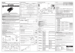
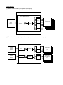
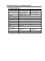
OPERATION MANUAL UFM-14DADA Digital Audio Distribution Amplifier UFM-18DADA Digital Audio Distribution Amplifier 1st Edition - Rev. 2 Precautions Important Safety Warnings [Power] Stop Do not place or drop heavy or sharp-edged objects on power cord. A damaged cord can cause fire or electrical shock hazards. Regularly check power cord for excessive wear or damage to avoid possible fire / electrical hazards. [Circuitry Access] Stop Do not touch any parts / circuitry with a high heat factor. Capacitors can retain enough electric charge to cause mild to serious shock, even after power is disconnected. Capacitors associated with the power supply are especially hazardous. Avoid contact with any capacitors. Hazard Unit should not be operated or stored with cover, panels, and / or casing removed. Operating unit with circuitry exposed could result in electric shock / fire hazards or unit malfunction. [Potential Hazards] Caution If abnormal smells or noises are noticed coming from the unit, turn power off immediately and disconnect power cord to avoid potentially hazardous conditions. If problems similar to above occur, contact authorized service representative before attempting to again operate unit. [Consumables] Caution The consumables used in unit must be replaced periodically. For further details on which parts are consumables and when they should be replaced, refer to the specifications at the end of the Operation Manual. Since the service life of the consumables varies greatly depending on the environment in which they are used, they should be replaced at an early date. For details on replacing the consumables, contact your dealer. Upon Receipt Unpacking UFM-14DADA/18DADA units and their accessories are fully inspected and adjusted prior to shipment. Operation can be performed immediately upon completing all required connections and operational settings. Check your received items against the packing lists below. ITEM UFM-14DADA or UFM-18DADA CD-ROM QTY REMARKS 1 1 front module 1 rear module 1 User manual Check Check to ensure no damage has occurred during shipment. If damage has occurred, or items are missing, inform your supplier immediately. Table of Contents 1. Prior to Starting.............................................................................................................................. 1 1-1. Welcome ............................................................................................................................... 1 1-2. About the UFM-14DADA/18DADA ........................................................................................ 1 1-3. About This Manual ................................................................................................................ 1 2. Panel Descriptions ........................................................................................................................ 2 2-1. Front Panel ............................................................................................................................ 2 2-2. Rear Panel ............................................................................................................................ 3 3. Connection .................................................................................................................................... 5 4. Internal Settings ............................................................................................................................ 7 4-1. Operation Mode (SW1) ......................................................................................................... 7 4-2. Other Settings (SW2) ............................................................................................................ 8 5. Specifications and Dimensions ..................................................................................................... 9 5-1. Specifications ........................................................................................................................ 9 5-2. Dimensions.......................................................................................................................... 10 1. Prior to Starting 1-1. Welcome Congratulations! By purchasing UFM-14DADA/18DADA Digital Audio Distribution Amplifier you have entered the world of FOR-A and its many innovative products. Thank you for your patronage and we hope you will turn to FOR-A products again and again to satisfy your video and audio needs. FOR-A provides a wide range of products, from basic support units to complex system controllers, which have been increasingly joined by products for computer video based systems. Whatever your needs, talk to your FOR-A representative. We will do our best to be of continuing service to you. 1-2. About the UFM-14DADA/18DADA UFM-14DDADA/18ADA AES/EBU format digital audio distribution amplifier is specifically designed for use with FOR-A’s Universal Frames UF-106B or UF-112. Module Mode Single channel UFM-14DADA Dual channel Single channel UFM-18DADA Dual channel Distribution Input 1 to four outputs Input 1 to two outputs Input 2 to two outputs Input 1 to eight outputs Input 1 to four outputs Input 2 to three outputs Features Input signal indication on the front panel The internal settings can be modified to set to single channel mode (1 way) or dual channel mode (2 ways) Mute data output (48kHz, 24bit) available when no audio signal is present (the following serial number range only) UFM-14DADA: Up to 10770159 UFM-18DADA: 10940001-10940008, 10940010-10940020, 10940027-10940036 10940038-10940040 1-3. About This Manual This manual is intended to help the user easily operate the UFM-14DADA/18DADA and make full use of its functions during operations. Before connecting or operating your unit, read this operation manual thoroughly to ensure you understand the product. After reading, it is important to keep this manual in a safe place and available for reference. 1 2. Panel Descriptions 2-1. Front Panel UFM-14DADA (1) POWER 1 UFM-14DADA UFM-18DADA 2 INPUT (2) (1) POWER UFM-18DADA (3) 1 2 INPUT Power indicator (2) INPUT 1 (3) INPUT 2 (4) INTERFACE (4) (OPTION) INTERFACE (2) (1) (OPTION) INTERFACE (3) (4) The power indicator is lit whenever the supply curcuit on the board is operating properly. This indicator lights whenever the proper digital audio signal is input to IN 1. This indicator lights whenever the proper digital audio signal is input to IN 2. Not used. 2 2-2. Rear Panel UFM-14DADA DIGITAL AUDIO IN IN1 IN 2 OUT 1 OUT 2 OUT 3 OUT 1-1 OUT 1-2 OUT 2-1 (1) OUT 4 OUT 2-2 UFM-14DADA (2) Single channel mode (1) (2) DIGITAL AUDIO IN IN 1 IN 2 OUT 1 OUT 2 OUT 3 OUT 4 Used for digital audio input connection. IN 1 is used to input digital audio signals. IN 2 is not used. Used for digital audio output connection. Digital audio signals input to IN 1 are output from OUT 1, OUT 2, OUT 3, and OUT 4 (one input to four outputs). Dual channel mode (1) DIGITAL AUDIO IN IN 1 IN 2 (2) OUT 1-1 OUT 1-2 OUT 2-1 OUT 2-2 Used for digital audio input connection. IN 1 and IN 2 are used to input digital audio signals. Used for digital audio output connection. Digital audio signals input to IN 1 are output from OUT1-1 and OUT1-2 (one input to two outputs). Digital audio signals input to IN 2 are output from OUT2-1 and OUT2-2 (one input to two outputs). 3 UFM-18DADA (3) 1 2 3 4 IN 1 OUT 1-1 DIGITAL AUDIO IN OUT 1-2 6 5 IN 2 OUT 2-1 OUT 1-3 OUT 1-4 7 8 OUT 2-2 OUT 2-3 DIGITAL AUDIO OUT UFM-18DADA (1) (2) Single channel mode (1) DIGITAL AUDIO IN IN 1 (3) DIGITAL AUDIO OUT 1–8 Used for digital audio input connection. Used for digital audio output connection. Digital audio signals input to IN 1 are output from DIGITAL AUDIO OUT 1 – 8 (one input to eight outputs). Dual channel mode (1) DIGITAL AUDIO IN IN 1 (2) IN 2 (3) OUT 1-1 OUT 1-2 OUT 1-3 OUT 1-4 OUT 2-1 OUT 2-2 OUT 2-3 Used for digital audio input connection. Used for digital audio input connection in dual channel mode. Used for digital audio output connection. Digital audio signals input to IN 1 are output from OUT1-1, OUT1-2, OUT1-3, and OUT1-4 (one input to four outputs). Digital audio signals input to IN 2 are output from OUT2-1, OUT2-2 and OUT2-3 (one input to three outputs). 4 3. Connection Refer to figure below for connecting the UFM-14DADA/18DADA to other devices. Note that before installing the UFM-14DADA/18DADA into the universal frame, you should thoroughly read the operation manual for the Universal Frame where you will be installing. UFM-14DADA (1) Single channel mode (one input to four outputs) Universal frame UFM-14DADA module OUT 1 Digital Audio Device DIGITAL AUDIO IN OUT 2 Input Detection OUT 3 Digital Audio Input Device 1-4 OUT 4 (2) Dual channel mode (one input to two outputs in two ways) Universal frame UFM-14DADA module Digital Audio Device IN 1 Digital Audio Device IN 2 Input Detection Input Detection 5 OUT 1-1 OUT 1-2 OUT 2-1 OUT 2-2 Digital Audio Input Device 1-2 Digital Audio Input Device 3-4 UFM-18DADA (1) Single channel mode (one input to eight outputs) Universal frame UFM-18DADA module OUT 1 OUT 2 OUT 3 Digital Audio Device DIGITAL AUDIO IN Input Detection OUT 4 Digital Audio Input Device 1-8 OUT 5 OUT 6 OUT 7 OUT 8 (2) Dual channel mode (one input to four outputs and one input to three outputs) Universal frame UFM-18DADA module OUT 1-1 Digital Audio Device IN 1 Input Detection OUT 1-2 OUT 1-3 Digital Audio Input Device 1-4 OUT1-4 Digital Audio Device OUT 2-1 IN 2 Input Detection OUT 2-2 OUT 2-3 6 Digital Audio Input Device 5-7 4. Internal Settings The following settings can be made via the front module of the UFM-14DADA/18DADA. Switch settings must be made prior to installing any module to the universal frame. Single channel mode/dual channel mode toggle switch SW2 SW 1 4-1. Operation Mode (SW1) SW1 is used to select between single channel mode (one way) and dual channel mode (two ways). SW1 A SW1 A A/B A/B Single Dual Jumper Setting A position A/B position Operation Mode Single channel mode Dual channel mode Factory default setting is single channel mode ( A position). 7 4-2. Other Settings (SW2) SW2 is for maintenance use only. If these settings are changed by mistake, refer to the table below to return them to the default settings. SW2 ON 1 2 3 4 5 6 7 8 4 Switch No. Factory Default 1 OFF 2 OFF 3 OFF 4 OFF 5 OFF 6 OFF 7 OFF 8 OFF 8 Description For maintenance use only. Do not change this setting. For maintenance use only. Do not change this setting. For maintenance use only. Do not change this setting. For maintenance use only. Do not change this setting. For maintenance use only. Do not change this setting. For maintenance use only. Do not change this setting. For maintenance use only. Do not change this setting. For maintenance use only. Do not change this setting. 5. Specifications and Dimensions 5-1. Specifications UFM-14DADA Distribution Single channel mode Dual channel mode UFM-18DADA Input 1 to four outputs Input 1 to eight outputs Input 1 to two outputs Input 2 to two outputs Input 1 to four outputs Input 2 to three outputs Audio input Digital audio 1.0V(p-p) 75Ω BNC Audio output Digital audio 1.0V(p-p) 75Ω BNC Digital Audio Format AES/EBU Sampling Frequency 32kHz – 96kHz Temperature 10°C – 40°C Humidity 30% – 90%(no condensation) Power Source + 12VDC to + 24VDC (supplied with universal frame) Power Consumption Approx.150mA Weight Approx. 0.5 kg Dimensions 106 (W) x 303 (D)mm Approx.160mA Front module Rear module 108.5 (W) x 20 (H) x 66.1(D)mm 108.5 (W) x 40.6 (H) x 66.1(D)mm Required slot 1 slot 2 slots Consumables No consumables are used in these products. 9 UFM-14DADA POWER INPUT 1 2 10 UFM-18DADA POWER INPUT 1 2 INTERFACE (OPTION) INTERFACE (O PTIO N) 106 106 303 303 66.1 66.1 17.2 13.5 108.5 1 2 3 4 108.5 IN 1 40.6 OUT 1-1 DIGITAL AUDIO IN OUT 1-2 OUT 1-3 6 5 OUT 1-4 8 7 DIGITAL AUDIO IN OUT 2-1 OUT 2-2 OUT 1 OUT 2-1 OUT 1-2 OUT 3 OUT 2 OUT 4 20 IN 2 OUT 2-3 DIGITAL AUDIO OUT IN1 UFM-18DADA IN 2 OUT 1-1 OUT 2-2 UFM-14DADA UFM-14DADA UFM-18DADA (All dimensions in mm.) 5-2. Dimensions Warning This equipment has been tested and found to comply with the limits for a Class A digital device, pursuant to Part 15 of FCC Rules. These limits are designed to provide reasonable protection against harmful interference when the equipment is operated in a commercial environment. This equipment generates, uses, and can radiate radio frequency energy and, if not installed and used in accordance with the instruction manual, may cause harmful interference to radio communications. Operation of this equipment in a residential area is likely to cause harmful interference, in which case the user will be required to correct the interference at his own expense. 2015/03/27 Printed in Japan FOR-A COMPANY LIMITED Head Office Overseas Division Japan Branch Offices R&D/Production 3-8-1 Ebisu, Shibuya-ku, Tokyo 150-0013, Japan Tel: +81(0)3 3446 3936 Fax: +81(0)3 3446 1470 Osaka/Okinawa/Fukuoka/Hiroshima/Nagoya/Sendai/Sapporo Sakura Center/Sapporo Center FOR-A Corporation of America 11155 Knott Ave., Suite G&H, Cypress, CA 90630, USA. Tel: +1 714 894 3311 Fax: +1 714 894 5399 FOR-A Corporation of America East Coast Office 2 Executive Drive, Suite 670, Fort Lee Executive Park, Fort Lee, NJ 07024, USA Tel: +1 201 944 1120 Fax: +1 201 944 1132 FOR-A Corporation of America Distribution & Service Center 2400 N.E. Waldo Road, Gainesville, FL 32609, USA Tel: +1 352 371 1505 Fax: +1 352 378 5320 FOR-A Corporation of America Miami Office 5200 Blue Lagoon Drive, Suite 760, Miami, FL 33126, USA Tel: +1 305 931 1700 Fax: +1 305 264 7890 FOR-A Corporation of Canada 1131A, Leslie Street Suite 209, Toronto, Ontario M3C 2J6, Canada Tel: +1 416 977 0343 Fax: +1 416 977 0657 FOR-A Europe S.r.l. Via Volturno 37, 20861 Brugherio MB, Italy Tel: +39 039 879 778 Fax: +39 039 878 140 FOR A UK Limited Trident Court, 1 Oakcroft Road, Chessington, KT9 1BD, UK Tel: +44 (0)20 3044 2935 Fax: +44(0)20 3044 2936 FOR-A Italia S.r.l. Via Volturno 37, 20861 Brugherio MB, Italy Tel: +39 039 881 086/103 Fax: +39 039 878 140 FOR-A Corporation of Korea 1007, 57-5, Yangsan-ro, Yeongdeungpo-gu, Seoul 150-103, Korea Tel: +82 (0)2 2637 0761 Fax: +82 (0)2 2637 0760 FOR-A China Limited 708B Huateng Building, No. 302, 3 District, Jinsong, Chaoyang, Beijing 100021, China Tel: +86 (0)10 8721 6023 Fax: +86 (0)10 8721 6033 FOR-A Middle East-Africa Office Dubai Media City, Aurora Tower, Office 1407, P.O. Box 502688, Dubai, UAE Tel: +971 (0)4 551 5830 Fax: +971 (0)4 551 5832 Agiv (India) Private Limited (FOR-A India) 85, V.N. Purav Marg Sion-Chunabhatti (E) Mumbai - 400 022 Tel: +91 22 2405 1258 Fax: +91 22 2405 0007 http://www.for-a.com/


![UFM-30CTL Operation manual[PDF:4.1MB] - FOR](http://vs1.manualzilla.com/store/data/005676883_1-d2048345a5eb1a6d8c39e09dd604009b-150x150.png)

![VTW Software Operation manual[PDF:17.4MB] - FOR](http://vs1.manualzilla.com/store/data/005725901_1-df2c6d7f9199f46fcf33ffa12e63545b-150x150.png)