1
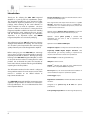
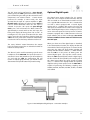
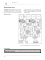
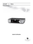
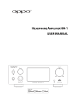
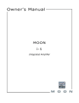
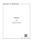
340i
Series
Integrated Amplifier
Owner’s Manual
340i Nēo Series
Owner’s Manual
Important Safety Instructions
1.
Read these instructions.
2.
Keep these instructions.
3.
Heed all warnings.
4.
Follow all instructions.
5.
Do not use this apparatus near water.
6.
Clean only with a dry cloth.
7.
Do not block ventilation openings. Install in
accordance with the manufacturer’s instructions.
8.
Do not install near any heat sources such as
radiators, heat registers, stoves or another
apparatus that produces heat.
9.
receptacles, and the point where they exit from the
apparatus.
Unplug
mains
cord
during
transportation.
11. Only use attachments and accessories specified by
the manufacturer.
12. Use only with the cart, stand, tripod, bracket, or
table specified by the manufacturer
or sold with the apparatus. When a
cart is used, use caution when
moving the cart/apparatus combination to avoid
injury from tip over.
13. Unplug this apparatus during lightning storms or
when unused for long periods of time.
Do not defeat the safety purpose of the polarized or
grounding type plug. A polarized plug has two
blades with one wider than the other. A groundingtype plug has two blades and a third grounding
prong. The wide blade or the third prong is
provided for safety. If the provided plug does not fit
into the outlet, consult an electrician for
replacement of the obsolete outlet.
14. Refer all servicing to qualified service personnel.
Servicing is required when the apparatus has been
damaged in any way, such as when the power cord
or plug has been damaged; liquid has been spilled
or objects have fallen into the apparatus; or the
apparatus has been exposed to rain or moisture,
does not operate normally, or has been dropped.
10. Protect the power cord from being walked on or
pinched, particularly at plugs, convenience
15. No naked flame sources, such as candles, should be
placed on the apparatus.
WARNING:
TO REDUCE THE RISK OF FIRE OR ELECTRIC SHOCK, DO NOT
EXPOSE THIS APPLIANCE TO RAIN OR MOISTURE.
340i Nēo Series
Important Safety Instructions
(cont’d)
The lightning flash with the arrowhead symbol, within an equilateral triangle, is
intended to alert the user to the presence of uninsulated “dangerous voltage” within
the product’s enclosure that may be of sufficient magnitude to constitute a risk of
electric shock to persons.
The exclamation point within an equilateral triangle is intended to alert the user to the
presence of important operating and maintenance (servicing) instructions in the
literature accompanying the appliance.
Marking by the “CE” symbol (shown left) indicates compliance of this device with the
EMC (Electromagnetic Compatibility) and LVD (Low Voltage Directive) standards of the
European Community
Please read all instructions and precautions carefully and
completely before operating your Nēo 340i Integrated Amplifier.
1.
ALWAYS disconnect your entire system from
the AC mains before connecting or
disconnecting any cables, or when cleaning any
component. To completely disconnect this
apparatus from the AC mains, disconnect the
power supply cord plug from the AC receptacle.
2.
The Nēo 340i must be terminated with a threeconductor AC mains power cord which includes
an earth ground connection. To prevent shock
hazard, all three connections must ALWAYS be
used. Connect the Nēo 340i only to an AC
source of the proper voltage; Both the shipping
box and rear panel serial number label will
indicate the correct voltage. Use of any other
voltage will likely damage the unit and void the
warranty
6.
NEVER wet the inside of the Nēo 340i with any
liquid. If a liquid substance does enter your Nēo
340i, immediately disconnect it from the AC
mains and take it to your MOON dealer for a
complete check-up.
7.
NEVER spill or pour liquids directly onto the
Nēo 340i.
8.
NEVER block air flow through ventilation slots
or heatsinks.
9.
NEVER bypass any fuse.
10. NEVER replace any fuse with a value or type
other than those specified
11. NEVER attempt to repair the Nēo 340i. If a
problem occurs contact your MOON dealer.
AC extension cords are NOT recommended for
use with this product. The mains plug of the
power supply cord
shall remain readily
accessible.
12. NEVER expose the Nēo 340i to extremely high
or low temperatures.
4.
NEVER use flammable or combustible
chemicals for cleaning audio components.
14. ALWAYS keep electrical equipment out of
reach of children.
5.
NEVER operate the Nēo 340i with any covers
removed. There are no user-serviceable parts
inside. An open unit, especially if it is still
connected to an AC source, presents a
potentially lethal shock hazard. Refer all
questions to authorized service personnel only.
15. ALWAYS
unplug
sensitive
electronic
equipment during lightning storms.
3.
13. NEVER operate the Nēo 340i in an explosive
atmosphere.
16. WARNING: Do not expose batteries or battery
pack to excessive heat such as sunshine, or fire
or the like.
Owner’s Manual
Table of Contents
Introduction
Unpacking
Installation & Placement
Front Panel Controls
Optional Digital Inputs
Optional Phono Section
Optional Balanced Inputs
Rear Panel Connections
SimLink™
Operating the Nēo 340i
Remote Control Operation
Specifications
6
7
7
8
9
10
11
12
13
13
14
16
www.simaudio.com
Simaudio Ltd., 1345 Newton Road
Boucherville, Québec J4B 5H2 CANADA
Date Code: 20150909
340i Nēo Series
Introduction
Thank you for selecting the Nēo 340i Integrated
Amplifier as a part of your hi-fi reproduction system.
This Integrated amplifier has been designed to offer
state-of-the-art high-end performance in an elegant
package, while retaining all the sonic hallmarks on
which Simaudio has made its reputation. We have
spared no effort to ensure that it is among the finest
integrated amplifiers available. We have been building
high-performance audio equipment for over 30 years,
and the know-how gained through our cumulative
experience is an important reason why MOON
Integrated amplifiers are so musically satisfying.
The performance of your 340i will continue to improve
during the first 300 hours of listening. This is the result
of a “break-in” period required for the numerous high
quality electronic parts used throughout this amplifier.
Before setting up your new Nēo 340i, we encourage
you to please read this manual thoroughly to properly
acquaint yourself with its features. We hope you enjoy
listening to the Nēo 340i Integrated Amplifier as much
as the pride we have taken in creating this fine audio
product. We understand the power and emotion of
music and build our products with the goal of faithfully
capturing these elusive qualities.
The information contained in this manual is subject to
change without notice. The most current version of this
manual is available on our official website at
http://www.simaudio.com
Your Nēo 340i Integrated Amplifier incorporates many
significant design features to achieve its “world-class”
level of performance. This is an abbreviated list of the
more important features:
Five line-level inputs including one front-mounted 1/8” minijack for personal media players.
One single-ended audio input which functions as a “passthrough”, bypassing the gain stage to accommodate a
component such as a home-theater processor, whose own
volume control is used instead.
Optional internal digital-to-analog converter circuit for use
with a PC, digital music server or external transport, etc.
Optional
internal phono preamp is available with
adjustments for gain level as well as capacitance and
resistance loading.
Optional line-level balanced XLR input.
Headphone output on ¼” TRS jack located on the front panel.
Proprietary MOON Bipolar Output transistors with
unprecedented gain linearity resulting in improved bass
response and even more accurate sonic reproduction.
Class A output to 5 watts for greater efficiency.
IR input for external control.
SimLinkTM controller port allows for 2-way communications
between other compatible MOON components.
RS-232 port for i) full unsolicited bidirectional feedback in
custom installation setups and ii) firmware updates.
12 Volt Trigger output.
Rigid chassis construction to minimize the effects of external
vibrations.
Designed to be powered up at all times for optimal
performance.
Low operating temperature for an ultra-long life expectancy.
6
Owner’s Manual
Unpacking
The Nēo 340i integrated amplifier should be removed from its box with care.
The following accessories should be included inside the box with your integrated amplifier:
9
9
9
9
9
AC power cable
‘CRM-2’ remote control with two ‘AA’ batteries
‘SimLink™’ cable with 1/8” mini plug terminations on each end
This owner’s manual
Warranty and product registration information (USA and Canada only)
Once the Nēo 340i is unpacked, inspect it thoroughly and report any damage to your dealer immediately. We
suggest that you keep all of the original packaging, storing it in a safe, dry place in case you’re required to
transport this product. The customized packaging is specially designed to protect the 340i from any potential
damage during transit.
Please write the serial number of your new Nēo 340i in the space provided below for future reference.
Serial Number
Installation & Placement
The Nēo 340i Integrated Amplifier is both powerful and
heavy. It requires reasonable ventilation to maintain an
optimum and consistent operating temperature,
especially since it will radiate heat when driven hard.
Consequently, it should be placed in a location with
empty space around it for proper heat dissipation. You
should never place another component on top of this
integrated amplifier. As well, it should be placed on a
solid level surface. You should avoid placing it near a
heat source or inside a closed cabinet that is not well
ventilated as this could compromise the amplifier’s
performance and reliability. The 340i uses a large
toroidal transformer in its power supply; even though it
is well shielded, you should not place this integrated
amplifier too close to source components sensitive to
EMI, such as turntables, phono preamplifiers and CD
Players. Finally, you should never place another
component directly on top of this integrated amplifier.
If you intend to use the Nēo 340i’s USB input
connection (PCM or DSD) with a Windows-based
computer, you will need to install our USB HD DSD
driver, which can be downloaded from the support
section of our website.
Note: Apple-based computers don’t require this
driver.
7
340i Nēo Series
Front Panel Controls
Figure 1: Nēo 340i Front panel
The front panel will look similar to Figure 1 (above). The large display window indicates the selected input source.
If your Nēo 340i includes the digital input option, additional information will appear in the display window. Refer
to the section entitled “Optional Digital Inputs” on page 9 for further details.
The “Standby” button disengages the input section
from the rest of the 340i’s circuitry. When in “Standby”
mode all audio circuitry remains powered up to help
maintain optimal performance. When switching back
from “Standby” to the “on” mode, the blue LED directly
above the display window will illuminate, As well, the
current ‘input’ will be memorized from the previous
listening session. The blue indicator LED turns off when
the 340i is in “Standby” mode.
The “MP” button (for Media Player) has its
corresponding input connection located on the right
side of the front panel for easy access. It uses a 1/8”
mini-jack connector which is the most common type of
connection found on portable media players. When
selected, the corresponding red LED, located to the left
of the button, will illuminate. When the “MP” input is in
use the display window automatically turns off. The
“Display” button allows you to turn the digital display
on and off.
The two (2) buttons labeled ◄ INPUT ► allow you to
sequentially scroll, either forward (►) or backward (◄)
through all of the available inputs. Depending on the
installed options, the order of the inputs is as follows
going forward (►): Basic Unit: “CD”, “A1”, “A2” and “A3”;
With all options installed: “CD”, “A1”, “A2”, “PH”, “B1”,
“D1”, “D2”, “D3” and “D4”
8
These abbreviations correspond directly to the labeling
of the rear panel inputs. By default the “CD” input is
intended for use with a CD Player, however you can
connect another type of source component to it. “A1”,
“A2” and “A3” are intended for use with any type of
source component that outputs analog signal. If you
have installed the optional phono section, the “A3”
input is replaced by “PH”. If you have installed the
balanced input option, “B1” will appear after the “A3” /
”PH” input. Finally, if you have installed the digital input
option, “D1”, “D2”, “D3” and “D4” will appear after either
“B1” (if you have the balanced option) or “A3” / ”PH”.
The optional inputs only appear if they are installed.
The “Spk off” button turns off the output signal only to
the loudspeakers connected to the Nēo 340i. This
feature is very useful when using headphones. When
this function is engaged, the red LED located to the
right will illuminate.
The “Mute” button mutes the output signal to the
loudspeaker terminals, headphone jack, as well as both
the fixed and variable line output connectors (refer to
the section entitled “Rear Panel Connections” for further
details). Pressing the “Mute” button a second time will
reinstate the volume back to its previous level. When
the output signal is muted, the red LED to the right will
repeatedly flash on and off.
Owner’s Manual
The “A2” input can be configured as a ‘pass-through’
which bypasses the 340i’s gain control section, allowing
you to control the gain setting via the connected source
component’s own volume control – a home theater
processor for example; In other words, this input
operates like the input of a power amplifier. In ‘passthrough’ mode, adjusting the volume on the 340i will
have no effect whatsoever when the “A2” input is
selected. To put the “A2” input into ‘pass-through’
mode, press and hold down the “Mute” button for
approximately 2 seconds while on the “A2” input. The
front panel display will change from “A2” to “HT”. To
reconfigure the “A2” input to function like the other
inputs, repeat the this procedure. Powering down the
340i via the rear panel rocker switch will automatically
reset the the “A2” to the factory default ‘normal’ mode.
Optional Digital Inputs
The rotary “Volume” control determines the output
level. The volume control has an embedded red LED to
indicate its actual position.
When you select one of the digital inputs as described
in the aforementioned section, the display window will
show which of the four digital inputs is selected. At the
same time, the right side of the display window will
initially show four dashes as follows “----” which indicate
that the 340i is in the process of locking onto the
external digital signal – this may take several seconds.
When the 340i successfully locks onto the digital signal,
the four dashes will be replaced by the sampling rate of
this digital signal. When the signal cannot be locked
onto, “----” remains in the display window. The optional
digital-to-analog circuit option inside the Nēo 340i is
capable of processing the following sampling rates:
32.0kHz, 44.1kHz, 48.0 kHz, 88.2kHz, 96 kHz, 176.4kHz
and 192kHz.
The “Phones” jack is used for connecting a pair of stereo
headphones to the Nēo 340i. The input connector is a
standard ¼” stereo TRS jack. When a pair of headphones
are used with the 340i, the loudspeakers will still
receive an output signal. However, you should use the
aforementioned “Spk off” button for private listening.
The Digital Input option includes four (4) separate
inputs: “D1” uses an optical Toslink connector, “D2” and
“D3” use S/PDIF on an female RCA connector and “D4”
uses a type-B USB connector. The “D1” is intended for
use with a source equipped with a TosLink digital
output such as a satellite dish receiver; The “D2” and
“D3” inputs are intended for use with a source equipped
with a S/PDIF digital output such as a DVD player, music
server or disc transport. The “D4” input is for use with a
computer equipped with a USB connector and music
player software such as iTunes or Winamp; You cannot
connect a USB flash drive or external hard drive to to
the “D4” input.
Figure 2: Nēo 340i Optional Digital Inputs – connection examples
9
340i Nēo Series
Optional Phono Section
The Nēo 340i Integrated Amplifier features an optional
MC/MM phono section that may be installed only by
your MOON Authorized Dealer or at the Simaudio
factory. This phono card is a very high quality design,
providing adjustments for both capacitance and
resisitance loading, as well as gain level. This flexibility
allows you to optimize the 340i for a wide variety of MC
and MM cartridges.
Circuit Board Layout:
Figure 3: Nēo 340i Optional Phono Section Circuit Board Layout
Internal Settings
We strongly recommend that you ask your MOON Authorized Dealer to make these adjustements. If you
decide to do this on your own, any damage cause to this component, including from static discharge, will
not be covered under warranty.
10
Owner’s Manual
There are three (3) types of settings available on the
optional phono section of the Nēo 340i; Capacitance
loading, Resistance loading, and Gain level. Each setting
is adjustable through the use of jumpers. For each type
of setting, there are 2 banks of jumpers – one each for
the left and right channels. This is the result of the
phono section’s genuine mirror-image circuit design
which yields exceptional stereo separation.
For MM cartridges, it is recommended that you leave
the jumpers inserted in the factory default setting of
100pF. Conversely, if you’re using a MC cartridge, you
should use the 0pF jumper settings by simply inserting
the supplied jumpers into each of the two left-most
sockets of jumpers C9 and C17.
Always disconnect all audio connections and the AC
power cord of your Nēo 340i prior to changing any of
the following input settings.
There are two (2) different settings available for gain
level. They are 40dB for MM cartridges and 60dB for MC
cartridges, which are represented by jumper socket J18
for the left channel and jumper socket J24 for the right
channel (refer to figure 2 – section labeled “GAIN”). The
factory default setting is for a MM cartridge , therefore
both jumpers will be found in each of the two right
most sockets labeled MM; It is highly recommended
that you do not use the jumpers labeled MC for an MM
cartridge as this will overload the 340i. When using a
MC cartridge, you should insert the supplied jumpers
into each of the two left-most sockets labeled MC.
There are six (6) screws, located on the top of the
chassis, that you must remove using a phillips head
screw driver. Once these screws are removed, carefully
lift off the chassis cover. Once the cover is removed, you
are ready to make all of the necessary internal
adjustments to the 340i phono module to achieve
optimal sonic performance.
Gain Level:
Resistance Loading:
Optional Balanced Inputs
There are two (2) different settings available for setting
the resistive load; 100Ω and 47kΩ which are
represented by jumper sockets R12 for the left channel
and jumper socket R29 for the right channel (refer to
figure 2 – section labeled “LOADING”). The factory
default setting is 47kΩ, therefore both jumpers will be
found in each of the two left most sockets.
For moving magnet (MM) cartridges, it is recommended
that you leave the jumpers inserted in the factory
default setting of 47kΩ. Conversely, if you’re using a
moving coil (MC) cartridge, you should use the 100Ω
jumper settings by simply inserting the supplied
jumpers into each of the two right-most sockets of
jumpers R12 and R29.
Capacitance Loading:
There are two (2) different settings available for the
capacitive load; 0pF and 100pF which are represented
by jumper sockets C9 for the left channel and jumper
sockets C17 for the right channel (refer to figure 2 –
section labeled “LOADING”). The factory default setting
is 100pF for a moving magnet cartridge, therefore both
jumpers will be found in each of the two right most
sockets.
The balanced input option provides for one additional
line-level input on an XLR connector. The “B1” input
uses a fully balanced differential circuit and is intended
for use with a source component that outputs a fully
balanced differential signal. The Nēo 340i optional
balanced input takes full advantage of the benefits of
balanced circuitry:
When using an unbalanced interconnect, the audio
signal runs through both the center wire and the
shield/ground wire. Any noise picked up by this
interconnect (ie. nearby magnetic fields such as an AC
power cord) will be reproduced by both the
preamplifier and amplifier, then heard through the
loudspeakers. Conversely, a balanced interconnect has
three separate conductors; one for the ground and two
for the actual signal. These two signals are identical
except that one is 180 degrees out of phase with the
other. For example, when one conductor is carrying a
signal of +10 Volts, the other will be carrying a signal of
–10 Volts. When these two inverted signals on a
balanced line are output from the Nēo 340i, any noise
picked up by the interconnect will be eliminated since a
differential circuit amplifies only the difference between
these two signals: Noise on a balanced interconnect will
be equal on both conductors and therefore cancel out.
11
340i Nēo Series
Rear Panel Connections
Figure 4: Nēo 340i Rear panel
The rear panel will look similar to Figure 2 (above). There are four (4) pairs of single-ended analog inputs on RCA
connectors labeled CD, A1, A2 and A3/P. The RCA input and output connectors on the rear panel have been color
coded: ‘white’ for the left channel and ‘red’ for the right channel. If your Nēo 340i is equipped with the optional
phono section, the input labeled ‘A3/P’ must be used to connect your turntable interconnect leads to this
integrated amplifier. If you don’t have the optional phono section installed, then this input can be used in the
same way as the CD, A1 and A2 inputs.
The Nēo 340i integrated amplifier also has two pairs of
non-amplified outputs labeled ‘FIX’ and ‘VAR’, located
next to the A3/P input. The ‘FIX’ output is intended as an
input to a recording device such as a cassette tape deck
or CD-Recorder Player. Keep in mind that the output
level is fixed and cannot be adjusted by the 340i’s
volume control. The ‘VAR’ output is designated for
output to a power amplifier with single-ended RCA
inputs if you wish to use your Nēo 340i only as a
preamplifier. Keep in mind that the output level is
variable and adjusted by the 340i’s volume control.
SimLink™ for more details. Next, there’s a 1/8” mini-jack
input for use with aftermarket infrared remote control
receivers. Then there’s a 12V trigger output on a 1/8”
mini-jack that can power up a connected component
(with a 12V trigger input) at the same time that the 340i
is powered up. Next, there’s a full-function bi-directional
RS-232 port for custom integration or automation on a
DB9 connector. Finally on the far right side is the “AC
Fuse” socket cover, the main power switch (“0”=off,
“1”=on) and the IEC receptacle, labeled “AC Power” for
the included AC power cord.
For Nēo 340i’s equipped with the balanced input option,
you will find one pair of XLR balanced inputs to the right
of these non-amplified outputs. These are intended to
be used with a source component that outputs a
balanced signal.
Don’t hesitate to use high quality interconnect cables*.
Poor quality interconnect cables can degrade the
overall sonic performance of your system.
For Nēo 340i’s equipped with the digital input option,
you will find 4 digital inputs labeled D1, D2, D3 and D4.
The D1 input is on an optical Toslink connector; both
the D2 and D3 inputs are on a S/PDIF connector; the D4
input is on a USB type B connector
Below the area reserved for the optional digital inputs
are a series of input/output connectors for custom type
installations: From left to right there are two (2)
“SimLink™” connectors labeled “in” and “out” on 1/8”
mini jacks. Please refer to the next section entitled
12
The Nēo 340i is equipped with a pair of gold-plated
binding posts. Connect your speakers, with the cables of
your choice, to the 340i’s speaker binding posts. Take
care to respect the polarity (“+” , “-” ) of the outputs.
Once again, don’t hesitate to use high quality speaker
cables*. Poor quality speaker cables can degrade the
overall sonic performance of your system.
Owner’s Manual
Connect the supplied AC power cable to the IEC
receptacle, located on the amplifier’s rear panel. Ensure
that the AC wall outlet you use has a functioning
ground. For the best sonic performance, it is preferable
that you plug your 340i directly into a dedicated AC
outlet and avoid using an extension cord. If you have
the time and willingness, consider installing a superior
quality AC wall outlet such as a hospital grade Hubbell*.
one component’s SimLink™ Out jack and another
component’s SimLink™ In jack. If you inadvertently
connect the cable between either two SimLink™ In or
two SimLink™ Out jacks, the SimLink™ communication
feature may not function. Also, there is no master
component in a SimLink™ chain; no one particular
component operates as the main communications
controller.
* Please speak with your MOON Authorized Retailer
about the benefits of high quality cables for your
system, and superior quality AC wall outlet.
Operating the Nēo 340i
SimLink™
The SimLink™ provides communication features
between various MOON components. For example, if
you were to connect the 260D to the 340i via the
SimLink™, pressing the X (play) button on the 260D will
cause the 340i to automatically switch to the input
labelled ‘CD’.
A second feature of SimLink™ involves the “Standby”
function. By pressing down and holding the “Standby”
button for 2 seconds on the either the 260D or 340i,
both units will go into “Standby” mode. The same logic
applies when switching from “Standby” to active mode.
If you are using the “MiND” Music Streamer and an
external digital-to-analog converter (DAC), you must
make a SimLink™ connection between the “MiND”s
SimLink™ out and the 340i’s SimLink™ in. The ‘Aux’
input is the default input for the “MiND” Music
Streamer; When you press the X (play) button on the
“MiND” App, the 340i will automatically switch to the
input labeled ‘Aux’. You can change these default
settings for the “MiND” as follows: Select the input that
you want as the new default for “MiND”, then press and
hold the “MP” button until the front panel display
begins to flash on and off.
The connection rules for the SimLink™ are very basic.
You must always connect the supplied cable between
We recommend leaving your Nēo 340i powered up at
all times to maintain optimal performance. When you
plan on being away for a few days, it may not be a bad
idea to power off your amplifier. Please keep in mind
that once fully “broken-in”, your 340i requires several
hours of operation before reaching optimal
performance after powering it up again.
Turning on your Nēo 340i for the first time
Prior to turning the amplifier on for the first time, make
sure that every cable is properly connected to avoid any
problems. Flick the main rocker switch, located on the
rear panel, labeled “POWER” to the ‘1’ (on) position. The
blue LED on the front panel will blink for up to 10
seconds while it achieves standby mode. When it stops
blinking and is not illuminated, your 340i is in standby
mode. Next, briefly press the push button labeled
“Standby” located on the front panel. You will hear a
very faint click sound confirming that everything is in
order. The blue LED on the front panel will illuminate,
indicating that the 340i is now powered up and ready
for use.
On and Off Sequence
To avoid having any annoying noises (ie. “thumps” and
“pops”) emanate from your speakers when powering
your 340i on or off, you should always power up any
source components prior to powering up your 340i. As
well, always power down your 340i prior to powering
down any source components.
13
340i Nēo Series
Remote Control Operation
The Nēo 340i Integrated Amplifier uses the ‘CRM-2’ full-function remote
control (figure 7). It operates on the Philips RC-5 communication protocol
and is can be used with other Simaudio MOON components.
The ‘CRM-2’ remote uses two AA batteries (included). To install them, simply
slide the back plate off in the direction of the arrow; insert the batteries in the
correct direction and then replace the back plate.
To engage the ‘CRM-2’ remote for use with the Nēo 340i Integrated
Amplifier, you must first press the button labeled AMP.
The POWER button located on the upper left will switch the integrated
amplifier to either ‘Standby’ or ‘On’ mode.
The DISPLAY button turns the front panel display on and off
The 2 buttons labelled ◄ INPUT ► allow you to sequentially scroll, either
backwards or forwards, through all six (6) available inputs. For example, to
switch from the “CD” to the “VIDEO” input you may press either ◄ INPUT
three (3) times or INPUT ► three (3) times. Pressing and holding down either
of these buttons results in only a single change to the selected input.
The 2 buttons labelled ▼ VOL ▲ allow you to control the volume level.
Pressing ▼ VOL results in a decrease in the volume level; Pressing VOL ▲
results in an increase in the volume level. You may either press and hold these
buttons down or press them briefly to make volume adjustments.
The MUTE button turns off the output volume. Pressing the “Mute” button a
second time will reinstate the output volume level back to its current setting.
NOTE: The buttons labelled ◄ BAL ► don’t affect the operation of the 340i.
Figure 5: CRM-2 Remote Control
14
Owner’s Manual
Remote operation with multiple MOON components
Figure 6: Remote Operation with SimLink™
In figure 6 we have a 180 MiND Music Streamer and a Nēo 340i Integrated Amplifier connected together via their
respective SimLink™ ports. The SimLink™ output on the 180 MiND is connected to the SimLink™ input on the 340i
(using a 1/8” mini-jack cable). When you launch the MiND App on your smart device and select this system’s
ZONE, both the 180 MiND and the 340i will turn on, with the 340i automatically switching to the MiND assigned
input, as described previously in the SimLink™ section. To shut down the system, press “Off” for this ZONE in the
MiND app
Figure 7: Remote Operation with 12V Trigger
In figure 7 we have a Nēo 340i Integrated Amplifier (used either as ONLY a preamplifier or in a bi-amping
configuration) and 330A Amplifier connected together via their respective 12V triggers; The 12V trigger output on
the 340i is connected to the 12V trigger input on the 330A (using a 1/8” mini-jack cable). When you turn on the
340i via remote control (or its Standby button), the 330A will also turn on. The same rule applies when you put the
340i into Standby mode.
15
340i Nēo Series
Specifications
Configuration
Stereo
Power Supply Transformer
400VA
Power Supply Capacitance
40,000μF
Class Of Operation – Amplifier
Class A/B
Single-ended inputs
4 (RCA)
Mini-jack input
1 (1/8”)
Optional Balanced inputs
1 (XLR)
Input Sensitivity
370mV – 3.0V RMS
Input Impedance
11,000Ω
Preamplifier output
1 (RCA)
Headphone output
1 ( 1/4” Stereo TRS)
Output Device Type – Amplifier
Bipolar
Output Power @ 8Ω
100 Watts per channel
Output Power @ 4Ω
200 Watts per channel
Gain
37dB
Signal-to-noise Ratio
110dB @ full power
Frequency Response
2Hz - 90kHz +0/-3.0dB
Crosstalk@ 1kHz
-88dB
Intermodulation Distortion
0.03%
Total Harmonic Distorition (20Hz-20kHz @ 1W)
0.015%
Total Harmonic Distorition (20Hz-20kHz @ 100W) 0.05%
Remote Control
Full-Function (CRM-2)
AC Power Requirements
120V / 60Hz ou 240V / 50Hz
Shipping Weight
28 lb. / 13 Kg.
Dimensions (W x H x D, inches / cm.)
16.9 x 3.5 x 14.8 / 42.9 x 8.9 x 37.6
Fuse Replacement:
16
120V version uses a 5A fast blow (3AG)
230V version uses a 3A fast blow (3AG)
Owner’s Manual
Specifications (cont’d)
Optional Phono Section:
Input Impedance - Adjustable
100 ohms and 47K ohms
Input Capacitance - Adjustable
0pF and 100pF
Gain - Adjustable
40dB and 60dB
Input overload @ 40dB / 60dB gain
58mV RMS / 3mV RMS
Signal-to-noise ratio (full scale @ 40dB / 60dB gain)
107dBr / 85dBr
Frequency Response
20Hz - 20kHz (±0.5dB)
Crosstalk @ 1kHz
-97dB
IMD
0.009%
THD (20Hz - 20kHz)
0.001%
Optional Digital-to-Analog Converter:
Digital Input Types
S/PDIF (RCA) x 2 USB x 1 TosLink x 1
Digital Input Impedance (S/PDIF)
75 ohms @ 0.5 Volts
DAC / Digital Filter
ESS9018K2M
DSD Data Rates
(2.8224MHz), Double (5.6448MHz) & Quadruple (11.2896)
DSD Sample Rates
DSD 64, DSD 128 & DSD256 via USB only
PCM Bit-depth range
16 - 32 bits (32-bit via USB only)
PCM Sampling Frequency Rates
44.1 - 384kHz (352.8 & 384kHz via USB only)
Frequency Response (audible)
20Hz - 20kHz +0/-0.2dB
Frequency Response (full range)
2Hz - 72kHz +0/-3dB
THD @ 1kHz, 0dBFS (A-weighted)
0.001 %
IMD
0.004 %
Dynamic Range
116dB
Signal-to-noise Ratio
115dB @ full output
Channel Separation
115dB
Intrinsic Jitter
< 25 picoseconds RMS
Balanced Pin Assignment:
Pin 1
Pin 2
Pin 3
Ground
Positive
Negative
NOTE: If you require the RS-232 codes for your Nēo 340i, please visit the "Contact Us" page
and complete the "Information request" form on our website at www.simaudio.com.
17
340i Nēo Series
18