1
Instructions & Operator Manual
R.E. Williams Contractor Inc.
www.rewci.com
TABLE OF CONTENTS
Product Information........................................................................Pg. 1
Gate Sizes...............................................................................Pg. 2
Doorway Anatomy...........................................................................Pg. 2
Where to Place the Gate................................................................ Pg. 3
Fitting Instructions........................................................................... Pg. 4
After-use Maintenance Instructions......................................Pg. 5
Storing your Floodgate..........................................................Pg. 5
Important Information............................................................Pg. 5
Special Situations
Doorways with No Reveal......................................................Pg. 6
Openings too wide for Flood Gates................................... Pg. 7
No Door Frame Fitting Options............................................Pg. 7
Instructions for Stanchion & Side Rails (Optional)........................Pg. 8
Choosing the correct size gates...........................................Pg. 8
Preparing the opening...........................................................Pg. 9
Masonry recessed entrance..................................................Pg. 9
Boring the holes for the base.............................................Pg. 10
Assembling the Angle Brackets..........................................Pg. 11
Preparing the ground surface.............................................Pg. 11
Inserting Base assemblies...................................................Pg. 12
General Maintenance and installation...............................Pg. 13
Warranty / Usage & Maintenance Log........................................Pg. 14
R.E. Williams Contractor Inc.
www.rewci.com
Product Information
How they work:
Flood Gates have been designed, engineered, and tested to minimize water intrusion, of depths up to
23 inches, through doors or other openings. Flood Gates are not designed to withstand impacts from
debris and/or waves. Effectiveness of Flood Gates is dependent upon pressure between sides and bottom
of opening. The structure in which it is installed must be in good shape and able to withstand this pressure.
Also, the structure surface must have a smooth surface capable of maintaining a seal.
(A) FLOOD GATE STANDARD – ADJUSTED FROM REAR OF PRODUCT (Shown without neoprene cover)
MAIN JACKING POINT (HORIZONTAL MOVEMENT OF BARRIER)
4 X ADJUSTING BOLTS
(TO CREATE DOWNWARD PRESSURE/SEAL)
SECURITY PIN
(NO ADJUSTMENT)
What they are made of:
A. 1” Steel Tube Frame- provides the support structure
B. 1/8” Front Steel Flat Sheets- block & take the weight of the water
C. 2 ton Scissor Jack – expands & creates a secure fit within door frame
D. Neoprene Sleeve- surrounds entire system & provides a watertight seal around its perimeter
A.
B.
D.
C.
Back shown without Neoprene Sleeve
Back shown with Neoprene Sleeve
Front shown with Neoprene Sleeve
1
R.E. Williams Contractor Inc.
www.rewci.com
Box components:
Flood Gate
Neoprene Sleeve
Hand Tool for
Ratchet Wrench
Scissor Jack
Tube of caulk
Instructions & Operations Manual
Gate sizes
QDFG30
Fits openings 30” – 35”
QDFG35
Fits openings 35” – 40”
QDFD40
Fits openings 40” – 45”
QDFG45
Fits openings 45” – 50”
Note:
For openings wider than 50”, stanchions
must be used. See Flood Gate Stanchion
Installation & Maintenance section
of this manual on page 8.
Doorway anatomy:
1. Width of opening (wall to wall within the reveal)
2. Reveal (measured from the outer side of the door frame, or furthest obstruction outwards, to the corner of the
face wall of the building)
3. Construction of reveal (make sure that it is a smooth surface- this will create the most effective seal- if it is not smooth between
Flood Gate & reveal use optional side rails.
4. Which way does the door/window open (inwards, outwards, sash, sliding, up and over, roller shutter, none opening etc.)
Example:
Door-frame
Inside of building
DOO
R
Reveal
Outer wall
Width of Opening
2
R.E. Williams Contractor Inc.
www.rewci.com
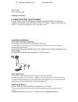
Where to place the gate:
Ideally, the Flood Gate should be placed on the outside of the property, in the reveal. All buildings differ
in the amount of reveal available and their surface type; it is recommended that you check your wall and
floor surfaces to ensure that water cannot seep under or around the barrier, nor into the plasterwork.
Add silicone caulk between Flood Gate and reveal as needed.
Example: Preferred Placement. (Outside)
Door-frame
Inside of building
DOO
R
FLOOD GATE
Outer wall
#1 Inward Opening Door (Preferred placement is on outside of property):
Place Flood Gate outside for continued access during flooding.
#2 Outward Opening Door:
Place Flood Gate inside for continued access during flooding.
Requires sufficient reveal for the Floodgate to grip the wall. Ideally, 2” (50 mm) of reveal is recommended,
although 1¼” (32 mm) - 1” (25 mm) may be sufficient as long as the Flood Gate can grip tight. This should be
measured from the furthest outward point on the door (usually the frame but look for threshold at
the bottom of the door that often protrude into the reveal space).
Measure this distance for Outward
Opening Door Inside Mount
Inside
Min. Reveal 1.25”-2” (32 mm - 50 mm)
FLOOD GATE PLACEMENT # 2
DOOR
Main wall of building
FLOOD GATE PLACEMENT # 1 (PREFERRED)
Outside
Min. Reveal 1.25”-2” (32 mm - 50 mm)
Measure this distance for Inward
Opening Door Outside Mount
3
R.E. Williams Contractor Inc.
www.rewci.com
Fitting Instructions
The Flood Gate is designed to seal off doorways from flood water. It can be reused for many years,
but must be properly maintained.
The Flood Gate system includes:
1.
2.
3.
4.
5.
6.
A metal frame expanding both horizontally and vertically - see Diagram A.
A neoprene sleeve - see Diagram B.
The rear of the sleeve allows access to the scissor jack and lower bolts - see Diagram C.
A hand tool for scissor jack. see Diagram A1
A ratchet wrench- see Diagram A2
Tube of Silicone Caulk - see Diagram A3.
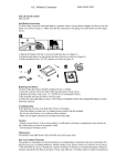
Installing your Flood Gate
Diagram A
Diagram A1
By following the procedures in the correct sequence, the barrier
will take approximately 2 minutes to install in position.
STEP ONE
Ensure that your entrance is smooth and clean of dust and debris
at the vertical and base area in preparation for positioning.
Silicone caulk may be applied to uneven surfaces between
wall and Flood Gate.
WARNING - Rough surfaces may damage the sleeve.
STEP TWO
Place the barrier with its face (see Diagram B) toward the flood
threat and as close as possible to your entrance in a solid reveal.
Diagram A2
Diagram B
WARNING - If you are not sure the reveal can withstand the forces
that will be applied to it you MUST seek advice from a structural
engineer.
STEP THREE
Keeping the unit in an upright position, apply downward pressure
to the unit, while adjusting the horizontal scissor jack (see Diagrams A & A1).
WARNING - Over extending the unit my weaken it and reduce its
effectiveness. It is recommended that expansion be no more than
5 inches (12.7 cm). If a larger unit would fit the opening, it must be
used instead of over extending a smaller unit.
Diagram A3
Diagram C
WALL
STEP FOUR
Adjust each of the 4 downward pressure bolts to a maximum
depth of ¼” (7 mm) to compact the sleeve along the ground (see Diagrams A & A2).
WARNING - DO NOT fully tighten these bolts as this will prevent further adjustment.
STEP FIVE
Silicone caulk may be used, in accordance with the manufacturer’s instructions, on the exterior edges of the frame
to ensure a complete seal - (see Diagram A3).
4
R.E. Williams Contractor Inc.
www.rewci.com
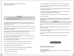
After-use Maintenance Instructions
1. Return the horizontal and vertical operating mechanisms to their closed position.
2. Remove the unit from its position.
3. Remove the sleeve and examine for damage caused by stress, use or wear and tear.
Repair or replace as necessary.
4. The sleeve can be hand washed in warm water up to 104° F (40° C). Rinse in cold water and hang
to dry in shaded area. DO NOT TUMBLE DRY.
5. Dry off excess moisture from the metal frame. Examine for damage caused by stress, use or wear and tear.
Apply rust proofing oil or grease to all expandable mechanisms.
6. Once all parts of the unit are dry, replace the sleeve over the metal frame so that access can be made to the
adjusting mechanisms on the back.
Storing your Flood Gate
1.
2.
3.
4.
5.
Store the unit in a secure location and only allow access by a responsible adult.
The unit should be stored in its closed and upright position. DO NOT STORE IN AN EXPANDED STATE.
Store the unit and its accessories in a dry and well ventilated area. DO NOT STORE IN DIRECT SUNLIGHT.
DO NOT EXPOSE THE PRODUCT TO EXTREME TEMPERATURES AND KEEP AWAY FROM OPEN FLAMES.
If you are storing more than one unit and do not intend on using the original packaging, the gates must be
stored face to face (The face as shown in Diagram B).
6. DO NOT STORE FACE TO BACK OR BACK TO BACK AT THIS CAN DAMAGE THE PRODUCTS.
7. Review the unit and its mechanisms periodically to ensure that the conditions of storage have not reduced
its effectiveness.
Important information
1.
2.
3.
4.
5.
6.
Do not handle the unit in an electrical storm.
Do not apply excessive force to any of the adjusting mechanisms of this product.
The unit must not be used in extreme temperatures and must be kept away from open flames at all times.
Do not apply to the unit, any solvents or other chemicals with which it may react.
The unit should only be installed by a responsible adult.
Metal finishing on this product can be sharp once the neoprene sleeve has been removed, wear suitable
protective gloves when handling metal frame.
7. Ensure that while adjusting the unit, all limbs, loose garments and other personal accessories are kept clear of
the moving parts.
8. The unit must not be used if damaged or incomplete.
9. This product is only to be used for the purpose for which it was designed and manufactured.
10. Absorbent Specialty Products (ASP), its associated entities and trading partners, do not accept responsibility for
any loss or damage caused by improper use of this product.
11. ASP, its associated entities and trading partners, do not accept responsibility for any loss or damage caused by
the ratchet wrench, hand tool or silicone caulk.
12. These products have a finite life and ASP, its associated entities and trading partners, do not accept responsibility
for any loss or damage resulting from the deterioration of these products.
5
R.E. Williams Contractor Inc.
www.rewci.com
Special Situations:
Doorways with no reveal:
Note: If you do NOT have a standard door that fits the Flood Gate, please review the following
options to adapt your door frame to accommodate the Flood Gate.
Many doors, particularly PVC doors, patio doors and French windows, are fitted almost flush with the outer face
of the building. In these situations, you would need to consider how you can extend the reveal sufficient to allow
the barrier to work.
Possible solutions:
SOLUTION # 1 Use a pair of side rails (optional) to fit to either the reveal or the outer face of the building
and provide a solid point to which the Floodgates can fit into. (See Example 1.)
Example 1: Side rails (optional accessory).
Side Rails
(optional)
Where Frames & Side Rails are fitted to the wall, the sides and bottom should be sealed with caulk
to ensure water cannot bypass the Flood Gate.
SOLUTION # 2 Secure a minimum 2 x 4 pressure treated post flush to exterior wall. Siding may have to be
adjusted to ensure a flush mount to wall. Apply silicone caulk between wall and post to
ensure water tight seal. Using a tapcon type bolt, ensure sufficient depth to allow Flood Gate
to function and post to resist force exerted when installing Flood Gate Barrier. (See Example 2.)
Example 2.
Where the pressure is exerted at 90° to the bolts securing the extra frame, the securing method should be able
to resist up to 1½ tons of pressure. Use Tapcon with Concrete shields (if necessary) to secure into brick, block, etc.
Added frame
(not included)
Door
Flood Gate
2-3”
3-4”
Apply silicone caulk to these joints.
6
R.E. Williams Contractor Inc.
www.rewci.com
Openings too wide for Flood Gates:
Example 3.
If opening is greater than 50”, additional frame may be added to decrease opening size. However, please
ensure that the screw heads do not protrude from the frame or stanchion and side rails (optional) may be
used to connect multiple units together.
Apply silicone caulk on outside joints and
along bottom of the new frame.
Flood Gate
Added frame
(not included)
Always ensure the joints between the new frame and the existing wall/frame are
‘sealed’ with a water resistant silicone caulk to protect against water intrusion.
No door frame options:
To fit the Flood Gate in a wall where the side walls are not adequate, you will need to create a side wall
support of some kind. Using optional Side Rails as shown in Examples 1 & 4 or adding additional wood
rails (not included). See Example 5
Example 4 (Optional Side Rails):
Side Rails
(optional)
Where Frames & Side Rails are fitted to the wall, the sides and bottom should be sealed with caulk
to ensure water cannot bypass the Flood Gate.
Example 5 (Wood rails):
New Frame
(not included)
Flood Gate positioned to flood side
The Frame must be a minimum of 1” (25 mm) deep, to provide sufficient support to the Flood Gate edges.
Its width dimension can vary & is not critical. The height of the Frame should match the height of the
Flood Gate at 27” (680 mm).
R.E. Williams Contractor Inc.
7
www.rewci.com
To connect multiple Flood Gates together the stanchion set must be used
Instructions for Stanchion & Side Rails (both optional)
The parts shown in illustrations (A) and (B) come in one kit with all of the necessary hardware.
Illustration (C) are the Side Rails & are sold in pairs.
ILL B
ILL A
Stanchion & Anchor
• Upright Stanchion
• Base
• Angle Brackets
Upright Stanchion
(ILL A)
(ILL A)
(ILL B)
• Side Rails (optional) (ILL C)
Flood water
comes from
this side
ILL C
TOP
Ground
Base
BOTTOM
UNDERGROUND
The evaluation should be done by a professional engineering consultant.
Prior to fitting the Flood Gate system to any existing structure or pre-construction, a full evaluation of the
structure must be completed to assess whether or not the structure is in fact suitable to withstand the
hydro dynamic and hydro static pressures that occur during a flood situation. This includes evaluating the
force impact of static water load pressures and moving pressures.
Choosing the correct size Flood Gate:
Determine the appropriate size or mixture of sizes of Flood Gates to fit your openings.
Flood Gate Size 30"- 35"
Max. Expansion: 39"
Height: 26.5"
Flood Gate Size 35" - 40"
Max. Expansion: 44"
Height: 26.5"
Flood Gate Size 40" - 45"
Max. Expansion: 49"
Height: 26.5"
Flood Gate Size 45" - 50"
Max. Expansion: 54"
Height: 26.5"
ILL D
The expandable Flood Gate unit should
not exceed 5 inches
D
The decision must be made prior to installing
the side rails and preparing the opening.
A
Once you have measured the opening
(D - see ILL D), you must choose
a combination of units
R.E. Williams Contractor Inc.
A = Gate Size
8
A
B width = 3.56”
Stanchion
Width
A
C width = 1 5/8”
Side Rails
Width
www.rewci.com
PREPARING THE OPENING
Ensure the planning and evaluation stage is complete and you have identified the products you require and
carried out any remedial work that is necessary to square and even wall reveals and ground area. If your
frame is not secure or is uneven, then installing side rails (optional) may be necessary.
Installing the Side Rails
Ensure the right and left jam plates are square with the floor at least 30 inches (76 cm) high.
(See illustration E and illustration F).
When the corners are squared, you can install the side rails. (See illustration G and illustration H).
Before you drill and install the side rail screws, you must apply a generous coat of
silicone caulk to the full length of each surface of the side rail where it comes in contact
with the backing surfaces (e.g. reveal, doorstop, jam plate, brick molding).
If you are fastening against a masonry surface use a carbide tipped 5/32 inch drill bit. Use screws suitable
for wood and concrete with shields. If threading into wood you need to drill a 3/32 inch hole first.
ILL E
ILL F
FRONT VIEW
30”
90º
90º
ILL G
90º
ILL H
TOP VIEW
DOOR STOP
RIGHT SIDE DOOR FRAME TOP VIEW
1 1/4”
DOOR JAM
DOOR
DOOR STOP
APPLY SILICONE THE
FULL LENGTH OF
BOTH FACES
THE 2 SIDE RAILS
MUST BE IN ALIGNMENT
JAM PLATE
SIDE RAILS
(OPTIONAL EXTRA)
SIDE RAILS
(OPTIONAL EXTRA)
ILL H
BRICK
MOLDING
When installing the tapered head screws, ensure the heads of the screws are flush
or below the top of the counter sink. If the screws are not flush or below they will
cut the outer fabric of the Flood Gate and cause a leak.
MASONRY RECESSED ENTRANCE
With a recessed entrance
the Floodgate System
mounts easily. Apply
silicone caulk to the
side rails which come in
contact with the property.
Squared to the walkway
and wall and screwed
into place.
R.E. Williams Contractor Inc.
WELDED CAP
GOES ON TOP
9
Note the design of the side
rails. There is a larger access
hole for the drill bit. The cap
on top of the side rail
prevents the Flood Gate
from riding up when
tightening the tension
bolts on the lower edge of
the Flood Gate, thus reducing
the amount of horizontal
pressure required to secure
the Flood Gate in place.
www.rewci.com
BORING THE HOLES FOR THE BASE
ILL I
CENTER LINE OF
STANCHION
90º
3”
STRAIGHT RIDGED
GUIDE BAR
SHIMS OR CLAMPS
ON BOTH ENDS
AS SHOWN
Whether or not you opt to use the side rails, the 3 in. / 76.2 mm centerline dimension
of the bored stanchion holes must always be maintained from whatever surface the back
CAUTION: face of the Flood Gate comes into contact with on the opening.
An engineer will advise on the most appropriate method of boring the hole. Two popular methods include (but are not
limited to) the use of a high pressure water saw or a diamond faced concrete hole drill.
Use a straight, rigid guide bar (not supplied), cut to the width of the door opening. A guide bar made of 1 ¼” x 1 ¼” x 1/8”
(31.75 mm x 31.75 mm x 3.17 mm) angle steel or aluminum is recommended.
Mark a line across the guide bar at appropriate intervals. These marks represent the center line spacing of the holes to be bored.
The intervals depend on the mix of Floodgate units you identified at the planning stage as the most suitable.
Lay a carpenters square on the floor against the inner surface of the guide bar and mark a vertical and horizontal line; this
becomes the center of each bored hole.
BORING THE HOLES FOR THE BASE
ILL J
8”
3”
3”
DOOR STOP
B
B
B
B
B
A
This illustration is an Example of an opening of 14¼ ft for (A). Using 5 Flood Gates, each stanchion, or
dimension (B) is positioned at their respective center lines.
NOTE: The 3 in. / 76.2 mm set back dimension to the center line of the bored holes is
critical to insure proper alignment of the Flood Gate panels.
10
R.E. Williams Contractor Inc.
www.rewci.com
ASSEMBLING THE ANGLE BRACKETS TO BASE
When the holes are bored and cleaned you are ready to set up the base.
1. Assemble the two angle brackets to the base using the four allen head cap screws.
Finger tighten at this point. (See illustration K)
NOTE: The front of the base is where the support rib is located (See illustration N).
2. Using a small square adjust the front angle bracket so it’s square to the top side edge
of the base. (see illustration K, L and N).
3. While holding the front angle bracket square to the base, tighten all four cap screws.
4. Re-check the front angle bracket again with the square (see illustration L).
5. Firmly clamp or block shim each end of the rigid straight edge into the side rails and against
the floor. Ensure that the center line marks (which are put on to the straight edge earlier) are facing
upward as these are the marks which you must later line up with the center line marks scribed on to the
face of the angle brackets (see illustration I).
ILL L
ILL K
A
FRONT
ANGLE
BRACKET
REAR
ANGLE
BRACKET
B
90º
The two angles are the same, but the Front Angle Bracket is
the one which is the positioning gauge for each stanchion,
therefore it must be squared with the side edge of the base
prior to tightening. (See illustration K). The Rear Angle
Face (A) and (B) must
be square to each other
as shown. A simple 6 in.
square works nicely for this.
Bracket need not be squared.
ILL M
PREPARING THE GROUND SURFACE AND BASE RECESS
ILL N
EXISTING
CONCRETE
SLAB
8”
EXISTING
CONCRETE
SLAB
CENTER LINE OF ANCHOR
SHOULD BE ON CENTRE
LINE OF HOLE AS SHOWN
TOWARDS
FLOOD
WATER
POSITIONING GAUGE
ANGLE FRONT
OUTSIDE OF BUILDING
10”
EXISTING
CONCRETE
SLAB
ANCHOR
ASSEMBLY
SUPPORT RIB
FACES TOWARDS
OUTSIDE OF
BUILDING
SUB
SOIL
Concrete floors and slabs vary greatly in terms
of thickness and type of concrete. You must
create a recess beneath the surface for the anchor which
SUB
SOIL
is then set in the concrete foundation. With this style of
construction the risk associated with under size floor
thickness, cracks and inadequate concrete reinforcement
is greatly reduced.
11
R.E. Williams Contractor Inc.
www.rewci.com
INSERTING BASE ASSEMBLIES
Pour and fill the hole with concrete to a depth of 4 inches from the top and tap or vibrate the concrete to
ensure it completely settles at the bottom of the hole. Position the base down into the concrete.
1. Align the center line marks on the angle brackets with the line marks on the center edge. (See illustration P).
Ensure you clamp the center line marks together so that both angle brackets are resting flat on the
surface of the floor. (See illustration N).
NOTE: Each base is designed with a 3” x 3” hollow square tube. At the very top of the tube and
through its rear wall, just under the threaded plate, there is a 3/4” hole in the tube. This hole allows air to
escape from the inside of the tube while the inside is filling with concrete. (See illustration O)
ILL O
AIR
RELIEF
HOLE
2. While filling with concrete, gently tap on the very
center of the top of the base with a block of wood
or handle end of a hammer.
It is critical that the inside of the base is
completely filled with concrete to maintain
maximum strength.
3. Ensure the top edge of angle brackets are flush with the
surface of the ground.
Do not remove the clamps and angle brackets for
at least 24 to 36 hours depending on the temperature,
humidity and soil mechanics to allow concrete to set.
ILL P
Dimension B
from ILL J
RIDGED
STRAIGHT
EDGE
CLAMP (4)
(not included)
Center line mark on
face of Angle Bracket
must line up with
marks on Ridged
Straight Edge
R.E. Williams Contractor Inc.
12
Center line mark on
Face of front angle
Bracket
www.rewci.com
GENERAL MAINTENANCE AND INSTALLATION
Removing the clamp
Keep the Allen Screws and Allen Wrench in a safe place as they will be needed to secure the
stanchion to the Base in the event of a flood.
ILL Q
Maintaining the Base
1. There are (4) 1/2 in. - grub screws with every stanchion.
These must be coated with a waterproof grease or
anti-seize compound and screwed into the holes on each plate.
This will protect the threads in the plate and allow traffic to move
across the anchor plate without damaging the threads
(See illustration Q).
2. These plugs should be flush with the top of the base
and no deeper. They should also be re-greased
periodically and after every use to ensure they will come
out when needed.
Before installing the stanchion
To prevent any leaking between the top of the Base and the bottom of the Stanchion there is a
machined 3/16” groove which should be filled with silicone caulk to add additional sealing
(See illustration R).
ILL R
SEALING
GROOVE
Maintaining the sealing surfaces
Always keep the top of the Base and the Bottom of the Stanchion clean and free of nicks and dents
as these are critical sealing surfaces.
13
R.E. Williams Contractor Inc.
www.rewci.com
Terms & Conditions
Flood Gate is intended to be used as outlined in this document and other Absorbent Specialty Products (ASP)
literature. Data and information provided in this document is for general information purposes only. Conditions
for each use of the Flood Gate will vary and are beyond the control of ASP. ASP cannot guarantee desired results.
When purchasing this product from ASP, you agree to assume all risks that may arise from ownership, installation,
and use of the Flood Gate and agree to release ASP from any and all claims brought by any person or entity
against ASP related to and/or arising from your ownership, installation, and/or use of the Flood Gate. ASP shall
not be liable for any improper or incorrect ownership, installation or use of this product and assumes no
responsibility for anyone’s ownership, installation or use of this product. In no event shall ASP be liable for any
direct, indirect, incidental, special, exemplary or consequential damages (including, but not limited to:
procurement or substitute goods or services; loss of use or profits; or business interruption) however caused
and on any theory arising in any way out of the use of this product, even if advised of the possibility of such
damage. This disclaimer of liability applies to any damages, injury or death, whether based on alleged breach
of contract, tortuous behavior, negligence or any other cause of action, including and not limited to damages or
injuries caused by any failure of performance, error, omission, defect or delay in operation.
Limited Warranty
ASP warrants this product and components to be free from defects in material and workmanship for a period of
one (1) year from date of shipment. If within the term of this warranty, if any Flood Gate component is found to be
defective upon inspection by an authorized Flood Gate representative, ASP will replace or repair, at ASP’s
discretion, any part found to be defective. Unauthorized modification of this product voids this limited warranty.
The neoprene sleeve is considered a “wear-item” and is not covered under this warranty. Replacements can be
purchased from ASP. Moving parts must be properly maintained prior to storage.
To make a claim under this warranty, contact ASP at this address:
Absorbent Specialty Products
51 Abbot Street
Suite #2
Cumberland, RI 02864
888-761-4405
[email protected]
Inspection and Maintenance
Usage and Maintenance Log
14
R.E. Williams Contractor Inc.
www.rewci.com