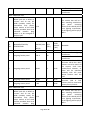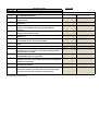
1
Annexure-II OIL INDIA LIMITED (A Government of India Enterprise) P.O. Duliajan-786602, Assam, India E-mail: [email protected] INVITATION FOR LOCAL COMPETITIVE BID OIL INDIA LIMITED invites Local Competitive Bid https://etender.srm.oilindia.in/irj/portal for the following items: (LCB) through its e-procurement E-Tender No Bid Closing/Opening Date Item Description SDI8849P16 Dt. 12.10.2015 03.12.2015 ELECTRICAL PMCC PANEL (QTY. – 15 NOS.) (Single Stage Two Bid System) SDI8859P16 Dt. 13.10.2015 (Single Stage Two Bid System) 03.12.2015 portal ELECTRICAL LIGHTING SYSTEM (QTY.- 01 NO. ) Tender fee (Non-refundable): Rs 1,000.00; Bid Closing/Opening Time: (11 Hrs.) IST/(14 Hrs.) IST; Period of sale of documents: Till one week prior to bid closing date. The complete bid documents and details for purchasing bid documents, participation in E-tenders are available on OIL’s e-procurement portal https://etender.srm.oilindia.in/irj/portal as well as OIL’s website www.oil-india.com. NOTE: All addenda, Corrigenda, time extension etc. to the tenders will be hosted on above website and e- portal only and no separate notification shall be issued in the press. Bidders should regularly visit above website and eportal to keep themselves updated. OIL INDIA LIMITED (A Government of India Enterprises) PO : Duliajan – 786602 Assam (India) TELEPHONE NO. (91-374) 2808719 FAX NO: (91-374) 2800533 Email: [email protected] ; [email protected] FORWARDING LETTER Tender No. : SDI8849P16 DT: 12.10.2015 Tender Fee : Rs 1,000.00 Bid Security Amount : Rs 8,47,300.00 Bidding Type : SINGLE STAGE TWO BID SYSTEM Bid Closing on : As mentioned in the e-portal Bid Opening on : -do- Performance Security : Applicable Integrity Pact : Applicable OIL invites Bids for PROCUREMENT OF PANEL FOR OCS/GCS – QTY = 15 NOS through its e-Procurement site under SINGLE STAGE TWO BID SYSTEM. The bidding documents and other terms and conditions are available at Booklet No. MM/LOCAL/E-01/2005 for E-Procurement LCB Tenders. The prescribed Bid Forms for submission of bids are available in the Technical RFx -> External Area - > Tender Documents The general details of tender can be viewed by opening the RFx [ Tender] under RFx and Auctions.. The details of items tendered can be found in the Item Data and details uploaded under Technical RFX. The tender will be governed by: a) “General Terms & Conditions” for e-Procurement as per Booklet No. MM/LOCAL/E01/2005 for E-Procurement LCB Tenders. b) Technical specifications and Quantity as per Annexure – 1A. c) The prescribed Bid Forms for submission of bids are available in the Technical RFx -> External Area - > Tender Documents. d) In the event of receipt of only a single offer against the tender within B.C. date, OIL reserves the right to extend the B.C. date as deemed fit by the Company. During the extended period, the bidders who have already submitted the bids on or before the original B.C. date, shall not be permitted to revise their quotation. e) All corrigenda, addenda, amendments, time extension, clarifications etc. To the tender will be hoisted on OIL’s website (www.oil-india.com) and in the e-portal (https://etenders.srm.oilindia.in/irj/portal) only and no separate notification shall be issued Page 1 of 6 in the press. Prospective bidders are requested to regularly visit the website and e-portal to keep themselves updated. f) Any sum of money due and payable to the contractor (including Security Deposit refundable to them) under this or any other contract may be appropriated by Oil India Limited and set-off against any claim of Oil India Limited (or such other person or persons contracting through Oil India Limited) for payment of sum of money arising out of this contract or under any other contract made by the contractor with Oil India Limited (or such other person or persons contracting through Oil India Limited). g) Bidder are advised to fill up the Technical bid check list (Annexure EEE) and Response sheet (Annexure FFF) given in MS excel format in Technical RFx -> External Area - > Tender Documents. The above filled up document to be uploaded in the Technical RFX Response. Special Note: 1.0 General Qualification Criteria: In addition to the general BRC/BEC, following criteria on Bidders' Experience and their financial capabilities shall be considered (documentary evidence to be provided along with the bid in Technical RFx -> External Area - > Tender Documents) as on the Bid Closing Date: Criteria Complied / Not Complied. Documentary evidence submitted / not submitted a) Annual financial turnover of the firm in any of the last 3 financial years or current financial year should not be less than Rs 847.25 Lakhs. For Annual financial turnover enclose the audited Annual Reports or balance sheet certified by a chartered accountant. 2.0 Application showing full address/email address with Tender Fee (Non-refundable) of Rs. 1,000.00 in favour of M/s Oil India Limited and payable at Duliajan is to be sent to HeadMaterials, Oil India Limited, P.O. Duliajan, Assam-786602. Application shall be accepted only upto one week prior to the bid closing date (or as amended in e-portal). The envelope containing the application for participation should clearly indicate “REQUEST FOR ISSUE OF USER ID AND PASSWORD FOR E TENDER NO …” for easy identification and timely issue of user ID and password. On receipt of requisite tender fee, USER_ID and initial PASSWORD will be communicated to the bidder (through e-mail) and will be allowed to participate in the tender through OIL’s e- Procurement portal. No physical tender documents will be provided. Details of NIT can be viewed using “Guest Login” provided in the eProcurement portal. The link to e-Procurement portal has been also provided through OIL’s web site www.oil-india.com. NOTE: a) Tender Fee may also be paid online upto one week prior to the bid closing date (or as amended in e-portal). Page 2 of 6 b) PSUs and SSI units are provided tender documents Free of Cost (as per govt guidelines), however they have to apply to OIL's designated office to issue the tender documents before the last date of sale of tender document mentioned in the tender. 3.0 The tender is invited under SINGLE STAGE-TWO BID SYSTEM. The bidders are required to submit both the “TECHNO-COMMERCIAL UNPRICED BID” and “PRICED BID” through electronic format in the OIL’s e-Tender portal within the Bid Closing Date and Time stipulated in the e-Tender. 3.1 Please ensure that Technical Bid / all technical related documents related to the tender are uploaded in the Technical RFx Response-> User - > Technical Bid only. The “TECHNO-COMMERCIAL UNPRICED BID” shall contain all techno-commercial details except the prices. Please note that no price details should be uploaded in Technical RFx Response. 3.2 The “PRICE BID” must contain the price schedule and the bidder’s commercial terms and conditions.The prices of the items should be quoted in “Conditions Tab”. Details of prices as per Bid format / Commercial bid can be uploaded as Attachment under the attachment option under “Notes & Attachments”. 3.3 A screen shot in this regard is given below. Offer not complying with above submission procedure will be rejected as per Bid Rejection Criteria mentioned in Annexure-CCC. Go to this Tab “Technical RFx Response” for Uploading “Technocommercial Unpriced Bid”. Go to this Tab “Notes and Attachments” for Uploading “Priced Bid” files. On “EDIT” Mode- The following screen will appear. Bidders are advised to Upload “Techno-Commercial Unpriced Bid” and “Priced Bid” in the places as indicated above: Page 3 of 6 Bid on “EDIT” Mode Area for uploading TechnoCommercial Unpriced Bid* Area for uploading Priced Bid** Note : * The “Techno-Commercial Unpriced Bid” shall contain all techno-commercial details except the prices. ** The “Price bid” must contain the price schedule and the bidder’s commercial terms and conditions. For uploading Price Bid, first click on Sign Attachment, a browser window will open, select the file from the PC and click on Sign to sign the Sign. On Signing a new file with extension .SSIG will be created. Close that window. Next click on Add Atachment, a browser window will open, select the .SSIG signed file from the PC and name the file under Description, Assigned to General Data and clock on OK to save the File. 4.0 Please note that all tender forms and supporting documents are to be submitted through OIL’s e-Procurement site only except following documents which are to be submitted manually in sealed envelope super scribed with Tender no. and Due date to Head Materials, Materials Department, Oil India Limited, Duliajan - 786602, Assam on or before the Bid Closing Date and Time mentioned in the Tender. a) Original Bid Security b) Detailed Catalogue (if any) c) Any other document required to be submitted in original as per tender requirement All documents submitted in physical form should be signed on all pages by the authorised signatory of the bidder and to be submitted in triplicate. 5.0 Benefits to Micro & Small Enterprises (MSEs) as per prevailing Govt guidelines as applicable on B.C date shall be given. MSEs who are interested in availing the benefits will upload with their offer proof of their being MSE registered for the item tendered. The MSE are also required to upload scanned copies of relevant documents indicating details of registration alongwith validity, name of the registering organization and details of the item, ownership etc,. failing which, their offer may not be liable for consideration of benefits to MSEs. Page 4 of 6 6.0 Bidders are requested to examine all instructions, forms, terms and specifications in the bid. Failure to furnish all information required as per the NIT or submission of offers not substantially responsive to the bid in every respect will be at the bidders risk and may result in rejection of its offer without seeking any clarifications. 7.0 Bidders must ensure that their bid is uploaded in the system before the tender closing date and time. Also, they must ensure that above documents which are to be submitted in a sealed envelope are also submitted at the above mentioned address before the bid closing date and time failing which the offer shall be rejected. 8.0 Bid must be submitted electronically only through OIL’s e-procurement portal. Bid submitted in any other form will be rejected. 9.0 SINGLE STAGE TWO BID SYSTEM shall be followed for this tender and only the PRICED-BIDS of the bidders whose offers are commercially and technically acceptable shall be opened for further evaluation. 10.0 a) The Integrity Pact is applicable against this tender. Therefore, please submit the Integrity Pact document duly signed along with your quotation as per BRC. OIL shall be entering into an Integrity Pact with the bidders as per format enclosed vide Annexure DDD of the tender document. This Integrity Pact proforma has been duly signed digitally by OIL’s competent signatory. The proforma has to be submitted by the bidder (along with the technical bid) duly signed (digitally) by the same signatory who signed the bid, i.e., who is duly authorized to sign the bid. Uploading the Integrity Pact with digital signature will be construed that all pages of the Integrity Pact has been signed by the bidder’s authorized signatory who sign the Bid. If any bidder refuses to sign Integrity Pact or declines to submit Integrity Pact with the offer, their bid shall be rejected straightway”. b) The name of the OIL’s Independent External Monitors at present are as under: SHRI RAGHAW SHARAN PANDEY, IAS (Retd.), Former Secretary, MOP & NG, e-Mail ID : [email protected] SHRI RAJIV MATHUR, IPS (Retd.) Former Director, IB, Govt. of India, e-Mail ID : [email protected] 11.0 The tender shall be governed by the Bid Rejection & Bid Evaluation Criteria given in enclosed Annexure-CCC. However, if any of the Clauses of the Bid Rejection Criteria / Bid Evaluation Criteria (as per Annexure-CCC) contradict the Clauses of the tender and / or “General Terms & Conditions” as per Booklet No. MM/LOCAL/E-01/2005 for Eprocurement (LCB Tenders) elsewhere, those in the BEC / BRC shall prevail. 12.0 To ascertain the substantial responsiveness of the bid OIL reserves the right to ask the bidder for clarification in respect of clauses covered under BRC also and such clarifications fulfilling the BRC clauses in toto must be received on or before the deadline given by the company, failing which the offer will be summarily rejected. 13.0 Please do refer the User Manual provided on the portal on the procedure How to create Response for submitting offer. \ Page 5 of 6 NOTE: Bidders should submit their bids (preferably in tabular form) explicitly mentioning compliance / non compliance to all the NIT terms and conditions of NIT. Yours Faithfully Sd(R ABARMAN) SR. MANAGER MATERIALS (IP) FOR : HEAD-MATERIALS Page 6 of 6 TENDER NO. SDI8849P16 DT: 12.10.2015 Annexure - CCC BID REJECTION CRITERIA (BRC) / BID EVALUATION CRITERIA (BEC) The following BRC/BEC will govern the evaluation of the bids received against this tender. Bids that do not comply with stipulated BRC/BEC in full will be treated as non responsive and such bids shall prima-facie be rejected. Bid evaluation will be done only for those bids that pass through the “Bid Rejection Criteria” as stipulated in this document. Other terms and conditions of the enquiry shall be as per General Terms and Conditions vide MM/LOCAL/E-01/2005 for E-Procurement LCB Tenders. However, if any of the Clauses of the Bid Rejection Criteria / Bid Evaluation Criteria (BRC / BEC) contradict the Clauses of the tender or MM/LOCAL/E-01/2005 elsewhere, those in the BRC / BEC shall prevail. Criteria 1.0 BID REJECTION CRITERIA (BRC): The bid shall conform generally to the terms and conditions given in this document. Notwithstanding the general conformity of the bids to the stipulated specifications, the following requirements will have to be particularly met by the Bidders without which the same will be considered as non-responsive and rejected. A) TECHNICAL: 1. Offers shall be complete in all respect to meet the technical specifications and general notes of the tender. 2. Bidder shall be a panel manufacturer/channel partner/authorized dealer of 415 VAC PCC/PMCC panels/switchboards. Bidders quoting on behalf of OEM shall submit copy of valid dealership certificate/authorization letter/certificate of channel partnership from the OEM along with the offer. 3. The bidder or their OEM shall have experience in design, manufacturing, testing, supply, installation and commissioning of minimum 5 sets (in single order or multiple orders) of 415 V PCC/PMCC panels with ACB/MCCB (air circuit breaker/moulded case circuit breaker) in any Central Govt./Govt. PSU/Public Limited Companies during last 5 years as on bid closing date of this tender. Bidders quoting on behalf of OEM shall submit either their own or OEM’s credentials such as PO copies with invoice/ performance certificate/completion certificate/ commissioning report etc. in design, manufacturing, supply and commissioning of panels. Page 1 of 5 Complied / Not Complied. (Remarks if any) B) COMMERCIAL: i). Validity of the bid shall be minimum 120 days from the Bid Closing Date. ii). Bid security: The bid must be accompanied by Bid Security of Rs 8,47,300.00 in OIL's prescribed format as Bank Guarantee or a Bank Draft/Cashier cheque in favour of OIL. The Bid Security may be submitted manually in sealed envelope superscribed with Tender no. and Bid Closing date to Head Materials, Materials Department, Oil India Limited, Duliajan- 786602, Assam on or before the Bid Closing Date and Time mentioned in the Tender. The Bank Guarantee towards Bid Security shall be valid for 10 months from Bid closing date. (i.e. upto 03.10.2016). Bid Security may also be paid online on or before the Bid Closing Date and Time mentioned in the Tender. If bid security in ORIGINAL of above mentioned Amount and Validity is not received or paid online within bid closing date and time, the bid submitted through electronic form will be rejected without any further consideration. For exemption for submission of Bid Security, please refer Clause No. 8.8 of General Terms and Conditions vide MM/LOCAL/E-01/2005 for E-Procurement LCB Tenders. The format of Bank Guarantee towards Bid Security (Annexure – VII) has been amended to Annexure – VII (Revised) and bidders should submit Bank Guarantee towards Bid Security as per Annexure – VII (Revised) only. In case of extension of Bid Closing date against the tender where a bidder has already submitted his bid with requisite bid security validity within the original B.C. Date, such bidders will extend validity of bid security covering the extended period of the bid closing date. iii). Bids are invited under “Single Stage Two Bid System”. Bidders have to submit both the “Techno-commercial Unpriced Bids” and “Priced Bids” through electronic form in the OIL’s e-Tender portal within the bid Closing date and time stipulated in the e-tender. The Techno-commercial Unpriced bid is to be submitted as per scope of works and Technical specification of the tender and the priced bid as per the online Commercial bid format. For details of submission procedure, please refer relevant para of General Terms and Conditions vide MM/LOCAL/E01/2005 for E-Procurement LCB Tenders. Any offer not complying with the above shall be rejected straightway. Page 2 of 5 v). Performance Security: a) The successful Bidder will have to provide Performance Security @ 10% of total cost of Equipment + Installation & Commissioning . The Performance Security must be valid for one year from the date of successful commissioning of the equipment or 18 months from the date of despatch whichever is earlier. The validity requirement of Performance Security is assuming despatch within stipulated delivery period and confirmation to all terms and conditions of order. In case of any delay in despatch or non-confirmation to all terms and conditions of order, validity of the Performance Security is to be extended suitably as advised by OIL. For exemption for submission of Performance Security, please refer Clause No. 9.12 of General Terms and Conditions vide MM/LOCAL/E01/2005 for E-Procurement LCB Tenders. iv). The Bank Guarantee should be allowed to be encashed at all branches within India. v). The prices offered will have to be firm through delivery and not subject to variation on any account. A bid submitted with an adjustable price will be treated as non-responsive and rejected. vi). Bids received after the bid closing date and time will be rejected. Similarly, modifications to bids received after the bid closing date & time will not be considered. vii). All the Bids must be Digitally Signed using “Class 3” digital certificate with Organisation’s name (e-commerce application) as per Indian IT Act obtained from the licensed Certifying Authorities operating under the Root Certifying Authority of India (RCAI), Controller of Certifying Authorities (CCA) of India. The bid signed using other than “Class 3 with Organisation’s Name” digital certificate, will be rejected. viii). Technical RFx Response folder is meant for Technical bid only. Therefore, No price should be given in Technical RFx Response folder, otherwise the offer will be rejected. ix). Price should be maintained in the “online price schedule” only. The price submitted other than the “online price schedule” shall not be considered. xi). Integrity Pact : OIL shall be entering into an Integrity Pact with the bidders as per format enclosed vide Annexure DDD of the tender document. This Integrity Pact proforma has been duly signed digitally by OIL’s competent signatory. The Page 3 of 5 proforma has to be submitted by the bidder (along with the technical bid) duly signed (digitally) by the same signatory who signed the bid, i.e., who is duly authorized to sign the bid. Uploading the Integrity Pact with digital signature will be construed that all pages of the Integrity Pact has been signed by the bidder’s authorized signatory who sign the Bid. If any bidder refuses to sign Integrity Pact or declines to submit Integrity Pact with the offer, their bid shall be rejected straightway”. xii). A bid shall be rejected straightway if it does not conform to any one of the following clauses: (a) Validity of bid shorter than the validity indicated in the Tender. (b) Original Bid Security not received within the stipulated date & time mentioned in the Tender. (c) Bid Security with (i) Validity shorter than the validity indicated in Tender and/or (ii) Bid Security amount lesser than the amount indicated in the Tender. (d) In case the Party refuses to sign Integrity Pact. (e) Average Annual Turnover of a bidder lower than the average Annual turnover mentioned in the Tender. 2.0 BID EVALUATION CRITERIA (BEC) The bids conforming to the terms and conditions stipulated in the tender and considered to be responsive after subjecting to the Bid Rejection Criteria as well as verification of original of any or all documents/ documentary evidences pertaining to BRC, will be considered for further evaluation as per the Bid Evaluation Criteria given below. A) TECHNICAL: i) The bids which qualify against the Bid Rejection Criteria will only be evaluated. ii) It is essential for OIL to remove the old panels from the installations for which a buy back system is incorporated. It is therefore mandatory for the bidders to quote against buy back of the dismantled panels on “as-is-where-is” basis. The quoted buy back price for the old panels shall be deducted from the total price against work schedule, i.e., supply +installation+ commissioning. Details of the buy-back arrangement are given in the clause “Special Conditions: Buy Back Arrangement” of Item Notes. Hence offers will be evaluated taking into account buy-back prices of old panels. (iii) Prices of spares shall be considered along with the price for main panels for evaluation of the bids. Bidder shall quote for all the panels/installation and commissioning jobs. (iv) As bidder has to buy back the old dismantled panels, bidder shall offer prices for both new panels along with spares (A) and buy-back prices of old panels (B). Final evaluation of suitable offers shall be based on the total price of offer, i.e., (A-B) and separate installation and commissioning charges. Page 4 of 5 B) COMMERCIAL: i). To evaluate the inter-se-ranking of the offers, Assam Entry Tax on purchase value will be loaded as per prevailing Govt. of Assam guidelines as applicable on bid closing date. Bidders may check this with the appropriate authority while submitting their offer. ii) Priced bids of only those bidders will be opened whose offers are found technically acceptable. The technically acceptable bidders will be informed before opening of the "priced bid". iii). To ascertain the substantial responsiveness of the bid OIL reserves the right to ask the bidder for clarification in respect of clauses covered under BRC also and such clarifications fulfilling the BRC clauses in toto must be received on or before the deadline given by the company, failing which the offer will be summarily rejected. NOTE: Bidders should submit their bids (preferably in tabular form) explicitly mentioning compliance / non compliance to all the NIT terms and conditions of NIT. -----xxxx----- Page 5 of 5 ANNEXURE-IA U TECHNICAL SPECIFICATIONS WITH QUANTITY Tender No & Date: SDI8849P16 DT: 12.10.2015 Design, Engineering & Manufacture, Supply, Installation, Testing and Commissioning of 15 nos. 415 V, 3 phase, 3 wire, 50 Hz Power and Motor Control Centre (PMCC) panels at the following Production‐Oil and Production‐Gas Installations of Oil India Limited, Duliajan, Assam Complied / Not Complied. (Remarks if any) All panels shall be similar in construction, except the quantities and capacity of incomers/outgoing feeders and starters and size. Details of individual panels for the installations are as per Annexure‐ Panel Feeder Lists. Item No. 10 PMCC Panel (Joypur OCS): Qty : 01 No. Detailed description of the PMCC panels: A. General Description of Panel: a) Panel shall be single front, extensible type, sheet steel clad, self‐supporting and floor mounted with integral base channel, cubicle type, indoor, dust and vermin protected. It shall contain copper bus bars (both horizontal main and vertical feeder) and individual motor starter/feeder panels suitable for operation from front side. Frames shall be made from suitably sized rigid framework of steel formed angles and channels and 2 mm thick CRCA sheet steel. Cubicles shall have individual front doors with sturdy hinges and fitted with special non‐deteriorating neoprene gasket. Lifting lugs shall be provided on the top of panel. b) Panel including busbar shall be suitable for future horizontal expansion on both sides. Busbars and cubicles/side walls of the panel shall be manufactured accordingly. c) Panel shall have horizontal main busbars(of ratings as given for individual panel details in the Annexure‐ Panel Feeder Lists) with alternate vertical busbar and cable alleys for proper distribution of panels. d) A 50 x 6mm GI strip should be provided on the backside of the panel with adequate holes (13mm dia each) with nuts, bolts and washers for making earth connections for all panels and cables. Length of GI strip shall be same as panel length. Zinc plated and passivated double earthing studs with nuts, bolts and washers shall be provided on the earthing strips. e) The PMCC panel shall be thoroughly cleaned and chemically pre‐treated for rust/grease removal and phosphate coating in a minimum seven tank chemical treatment process. After chemical treatment, the panel shall be powder coated/polished with epoxy resin based powder and stoved in a stoving oven. Coating (dry film) thickness shall be 50 micron minimum as per IS: 13871‐2006. Finish shall be glossy. f) Colour of the PMCC panel shall be light grey to IS: 5 of 2007. g) The complete PMCC panel shall be based on a 75x40x6 mm channel with suitable grouting arrangement. h) Danger plates (415 VAC) shall be fixed on both front and rear of panel including the Page 1 of 32 busbar chambers. i) Panel and its components shall be conforming to IS: 8623, 8828, 13947 and 12640 & IEC: 60947 & 60439‐1. Protection shall be as per IP‐54. Ambient‐40°C (Max)/ 5°C (Min), Humidity‐95% (Max). j) All components used must be suitable for the environment as mentioned. All hardware should be of high tensile steel & galvanised/ Zinc passivated. Size of spring washers & flat washers should be as per relevant IS for individual bolt. Panel can also be of modular design, with plug‐in/withdrawable type switchgear panel. In case of modular panels, the matching parts (male/female) in both power and control circuit shall be of high accuracy and quality for perfect insertion. The plug‐in panels must be designed for easy insertion and withdrawal. Component layout shall be designed for maximum heat dissipation. Cable alleys shall be provided for incoming and outgoing cables with labeled terminal blocks and fixing arrangement of cables. Limiting dimensions of the PMCC panel are 6000 mm (width) x 700 mm (depth/thickness) x 2300 mm (height). Minimum working height shall be 300 mm. However, minor deviation regarding size can be accepted after discussion with OIL. B. Detail Description of Panel All the panels shall have the same specifications except the no. of feeders/starters in each and hence size. The nos. of feeders and starters for each of the panels including the incomers (suitable for the designated installations) are given in the Annexure‐ Panel Feeder Lists). System basic design data: Rated Service Voltage‐ 690 V Rated operational voltage‐ 415 V Max‐ Min. ambient temp‐ 40/5 deg. Celcius Humidity‐ 98% Max. Altitude‐ 100 m above MSL a) Incomers: There will be 2 (two) incomers, with 690V (Ue), 800V (Ui), 50 kA Icu (ICu=Ics) or above breaking capacity rated three pole withdrawable type air circuit breaker or plug‐in type moulded case circuit breaker, electronic/ microprocessor controlled with LSIg protection with adjustable settings [long delay (0.4‐1.0 In)/short delay (1.5‐10 long delay setting)/Instantaneous (1‐ 10 x In & OFF)/ground fault (0.1‐1.0 In) with individual time settings] with separate earth leakage module. Incomer minimum rating will be 630 A. Incomers above 630 A will be air circuit breaker, rated 1000 A. Earth leakage module shall have range of 0.03‐3.0 Amps and 0‐ 3 seconds, both current and time in adjustable steps. The earth leakage protective device may either be in‐built earth leakage trip module (in case of ACB and larger MCCBs), a CBCT + EL module combination (for MCCBs) or a separate, but MCCB mountable EL module. The ACBs/MCCBs shall conform to IEC 60947/IS 13947‐2, tropicalized to Class‐II (high humidity). Make: Schneider/Legrand/Siemens/L & T/ABB /Indo‐Asian. Ratings of the incomer panel ACBs/MCCBs are as given in the Annexure‐ Panel Feeder Page 2 of 32 Lists. All incoming and outgoing terminals of ACBs/MCCBs shall be fitted with bus links or spreader links supplied by ACB/MCCB manufacturer or brought out phase links of copper in rectangular sections with holes. Zinc passivated nut bolts with flat and spring washers for connection shall be provided for cable termination (2 or 3nos. of 3.5x240 sq mm LT PVCA copper cable for incoming supply for each incomer, depending on incomer current rating). The links shall be supported on non‐hygroscopic insulating bars of FRP/DMC based materials and shall be of suitable size for cable termination. The vertical distance between the centre of connection hole in the links for cable connection and the bottom gland plate shall be minimum 450 mm. Detachable gland plate shall be provided which shall be suitable for fixing two/three nos. of cable glands of the size mentioned. Metering/ Instrumentation for the Incomer (two sets, one set for each incomer): 1) 01 no.‐ Digital multifunction meter indicating Voltage, Current, Frequency, Power factor, Power and Energy with RS‐485 capability; make‐ Swift‐Encore/Siemens/HPL‐ Socomec/Merlin Gerin (Schneider). The multi‐function meter shall also have function for maximum demand (maximum demand indicator). 2) 03 nos.‐ Current transformers, wire wound, 1000/5, 15 VA, Class 1 to IS: 2705; make‐ AE/Kappa/Siemens 3) 08 nos.‐ LED indication lamps for indication of ‘Supply ON’ (for R/Y/B phases), ‘CB Off/CB On/Trip‐OC/Trip‐SC/Trip‐EF’; make‐ Teknik/Siemens/Schneider/ABB 4) As required‐ MCBs for control circuit and instrument circuit protection; ‘C’ curve. make‐Schneider/Legrand/ABB/Indo‐Asian b) Busbars and bus chamber: Bus chamber shall be steel clad having front and rear bolted covers. The busbars shall consist of 1 set of hard drawn, high conductivity, three phase, electrolytic grade, virgin copper bars of purity 99.99% or better, rated minimum 1000/1250 Amps, supported at sufficient intervals on non‐hygroscopic, non‐inflammable glass reinforced plastic (GRP)/sheet moulding compound (SMC) supports. Busbars shall be rated to withstand short circuit fault currents of 50 KA for 1 second. The busbar individual phases shall be colour coded for easy identification. Main busbars shall be full length of the panel. Vertical bus bars for feeding individual starter/feeder shall be full height of the panel. Sufficient clearance shall be maintained in the bus chamber for proper cooling of the busbar. Busbar should be extensible type to facilitate future extension. c) Starter/Feeder Panels: No. and ratings of Starters/feeders will be as per individual panel outgoing details, given in Annexure‐ Panel Feeder Lists. However general description for these shall be as follows. Description of Starter/feeder panels: 1) MCCB isolator (Isolation requirement): Each feeder/motor starter cubicle shall be provided with one no. 690 V(Ue), 800V(Ui), min. 36 kA breaking capacity, three pole MCCB fitted with inbuilt microprocessor Page 3 of 32 controlled long time, short time, instantaneous, ground fault (LSIg) and earth leakage releases with adjustable settings for current & time and with Rotary Handle operating mechanism. For feeder panels also, threepole MCCBs shall be used with identical capacity and type. The MCCBs shall be operated from outside the panel. The MCCB handles shall also project outside the panel doors enabling breaker operation from outside the panel. All MCCB used shall be suitable for positive isolation requirement as per IEC 60947‐2. Control supply of individual starters shall be tapped from its own line; the starter shall be in‐operative if the MCCB is off. However remote start/stop pushbutton supply shall be from 30 V phase‐to‐phase (maximum) auxiliary bus. 2) Panel components: Various starters and feeders shall be housed in individual cubicles. Components shall be mounted on sheet steel base and all apparatus shall be suitable for front removal. All starters/feeders shall have suitably rated MCCBs as incomers. For feeder/starters above and including 20 HP, MCCB incomer connection to busbars shall be through suitably rated copper bus links/spreader bars only. This is to avoid mechanical stresses that may develop during short circuit condition. Motor starters above and including 12.5 HP shall be star‐delta starters (except soft starters). Starters below 12.5 HP shall be DOL starting. Earth leakage module shall have range of 0.03‐3.0 Amps and 0‐ 3 seconds, both current and time in adjustable steps. The earth leakage protective device may either be in‐built earth leakage trip module (in case of ACB and larger MCCBs), a CBCT + EL module combination (for MCCBs) or a separate, but MCCB mountable EL module. Starter panel components like MCCBs, contactors, overload relays, RCBOs etc. shall conform to IEC60947‐2/IS: 13947‐2 and IS: 12640. All starter/feeders shall be provided with Type II protection. The control voltage of remote push button stations for motors is to be limited to maximum 30 V as per CEA Regulations, 2010. An intrinsically safe barrier shall be placed between the remote pushbutton station and motor starter panel, so that no dangerous voltage (for hazardous area) is transmitted for operation of the remote pushbutton station. The intrinsically safe barrier may be placed in the motor starter panel. Low voltage power supply to panel contactors and intrinsically safe barrier power requirement may be generated through two nos. step down transformers placed at both ends of the panel. The low voltage secondary side of the transformers shall be connected to an auxiliary bus. Control voltage shall be tapped to individual motor starter/feeder panels from the auxiliary bus through auxiliary control MCBs in each starter/feeder panel. [As supply source (captive gensets) shall be installed with NGRs, the neutral cannot be used anywhere in the system. Hence all control voltages will be referred to phase‐phase only.] Control voltage transformers shall have individual MCBs of sufficient ratings as breakers in both primary and secondary sides (individual for each transformer). Each of the transformers shall be able to take the entire control voltage load of the panel. One of the transformers shall be on line and the other shall be standby. Page 4 of 32 Main components of individual starter/feeder panels (other than main incomers): Starter panel components (including soft Feeder panel components starter panels) Incomer MCCB Incomer MCCB EL detection module/CBCT+ELCB EL detection module/ CBCT+ELCB combination combination Magnetic contactor (for DOL or SD LED indication lamps for feeder starters) on/off/trip status Soft starter (only for soft starter panels) Starting and Bypass contactors (only for soft starter panels) Thermal overload relay Low voltage (maximum 30 V) supply for remote push button system, including all accessories Remote/local selector switch Local on/off (start/stop) pushbuttons Intrinsic safety barrier for the remote control system Ammeter (digital) CT, where required Control voltage transformers Control MCBs LED indication lamps for on/off/trip status i) Incomer MCCB (as isolator/main switch) ii) Earth leakage module in the downstream of MCCB (integral to MCCB, or through separate CBCT & earth leakage relay or directly mountable on the MCCB (as an add‐on block) with variable current and time settings (0.03‐ 3.0 A and 0‐3 second, in steps) iii) For starter panels only‐ Motor Starter magnetic contactor/s and adjustable thermal overload relay iv) Soft starter panels‐ Individual soft starter cubicles shall have individual soft starter units. Other components such as cubicle incomer MCCB, earth leakage protection with the MCCB, main (starting) contactor, running contactor, thermal overload relay, remote/local selector switch, start/stop pushbuttons, LED indications, intrinsically safe barriers etc. shall be as in the normal star/delta or DOL starter panels. v) Timer for star delta starter, range 0‐60 seconds, adjustable in steps/continuous vi) Remote/ local selector switch‐ for facilitating remote/local starting of motor vii) Local start/stop switch‐ for starting/stopping of motor from panel viii) Low voltage (maximum 30 V) supply system for remote pushbutton station, Page 5 of 32 ix) along with intrinsically safe barrier for isolating hazardous areas and non‐ hazardous areas (safe area), i. e., in the panel. Intrinsically safe isolators/barriers shall be in the panel. For starter panels only‐ Ammeter (accuracy class 1.0), directly mounted for starters below 10 HP and through CT for and above 10 HP. 'On', ‘Off’ and ‘Overload' LED type indicating lamps x) Make/models of the components: Only the following makes/models of the components shall be used in the starter/feeder panels. Name of component Make ModelRating Main panel incomer ACB with EDO type, fault level 50 kA or above at 500 VAC. minimum LSIg Protection Electrically and manually operated with O/c, S/c, (1000 A) (where ACB as instantaneous and earth fault protection. Spring charging shall be motorized with 230 Vac as well as manual. incomer is mentioned) Make: Schneider Masterpact NW series with Micrologic 6.0A or better /Siemens WL series with ETU GT‐N/GT‐ H/ABB‐ EMax series with ETU PR 121/122 / Legrand‐ DMX3‐N with ETU cat no. 028802 MP4 LSIg or MP6LSIg Main panel incomer MCCB Schneider Electric (Compact NSX with Micrologic 6.0 and with minimum LSIg Protection above)/ Legrand (Model DPX/DPX3 range with electronic (say for 630 A range) LSIg release‐Sg type)/ Siemens (Sentron VL with ETU 45 (where MCCB as incomer is LSIg) /ABB (Tmax T6 with PR 222)/Indo‐Asian (X TEC series with X5/X6 LSIg release) mentioned) Digital multifunction meter Swift‐Encore (Swift Encore SW3)/ Siemens (PAC 3100)/ HPL‐Socomec (Diris A40)/Schneider (EM 6400 accuracy 0.5) Incomer MCCB (for individual Schneider Electric(Compact NSX range) /Legrand (DPX3 cubicles) with LSIg Protection range)/Siemens (Sentron 3VT series)/ ABB (Tmax series)/Indo‐Asian (X‐TEC series) RCBO Schneider Electric/Legrand/Siemens/GIC CBCT+ELCB combination Schneider Electric (RH 197P+GA300 etc.)/ Legrand (0260 88+ 0260xx series)/GIC Magnetic contactor (for DOL Schneider Electric (TeSys series)/Siemens (3RT series)/ or SD starters) ABB (AXX series) Soft starter ABB/Siemens/Schneider Starting and Bypass contactors Schneider Electric/Siemens/ABB (only for soft starter panels) Thermal overload relay Schneider Electric/Siemens/ABB Timer Schneider/Siemens/ABB/Indo‐Asian Remote/local selector switch Siemens/L&T/Kaycee/Teknik/ABB Local on/off (start/stop) PBS Kaycee/L&T/Recom Intrinsic safety barrier for the Omega/R‐Stahl/ MTL/ Pepperl+Fuchs remote control system Ammeter (digital) AE/Rishabh/L & T/Schneider Control supply transformer AE/Kappa/Siemens/reputed make Page 6 of 32 CT, where required AE/Kappa/Siemens Wire wound, 1000/5, 15 VA, Class 1 to IS: 2705 LED indication lamps for L&T/BCH/ Teknik/Siemens/ As per voltage on/off/trip status Schneider/ ABB/Binay rating, all with LVGP Control MCBs Schneider/Legrand/ABB/ ‘C’ Curve Siemens/Indo‐Asian Important points to be considered while designing the starter/feeder panels: i) **As the panel will be installed in an oil/gas mine, as per Central Electricity Authority Regulations 2010, the remote starting facility of starter panels for motors shall be suitable for voltage below 30 Volt and intrinsically safe. The control voltage of remote push button stations for motors is to be limited to maximum 30 V as per CEA Regulations, 2010. An intrinsically safe barrier shall be placed between the remote pushbutton station and motor starter panel, so that no dangerous voltage (for hazardous area) is transmitted for operation of the remote pushbutton station. The intrinsically safe barrier may be placed in the motor starter panel itself. ii) Low voltage power supply to panel contactors and intrinsically safe barrier power requirement may be generated through two nos. step down transformers placed at both ends of the panel. The low voltage secondary side of the transformers shall be connected to an auxiliary bus. Control voltage shall be tapped to individual motor starter/feeder panels from the auxiliary bus through auxiliary control MCBs in each starter/feeder panel. iii) All ACBs & MCCBs shall have provision for padlocking and shall be provided with suitable locks with two keys for each lock. iv) MCCBs, contactors, overload relays shall be of one make only. However, earth leakage relays, CBCT etc. may be of different make than contactors/OLR etc. CBCT and sensing earth leakage relay shall be compatible and from the same manufacturer. v) One rating of components shall be used for a range of starters (e.g., one rating of contactors in all starters up to 20 HP, but suitable range of overload relay to match the panel rating). All device selection shall take motor starting current into consideration. vi) For hazardous areas, 3 phase 3 wire connection shall be used including lighting loads (through lighting transformer). However, in case 3 phase, 4 wire supply (for neutral) is required, power from the 3 pole feeder will be supplied through isolation transformer (415 V/415 V, delta/star‐neutral) only. Two nos. of such feeders (capacity30 KVA each, one running and one standby) shall be accommodated in each PMCC panel. [Isolation transformer is not in the scope of supply.] vii) Outgoing cables/bus links from the individual panels shall be terminated in individual TBs mounted in cable alleys. TBs will be sufficiently rated. Separate control and power TBs are to be used. TBs shall be covered/separated with insulation barriers. viii) 1 (one) cubicle box with three phase 63 A RCBO as incomer and 12 nos. DP MCBs (suitably rated) for illumination and power socket outlets for the panel installation area shall also be separately provided. This cubicle box will be a stand‐alone type panel. Incoming power to the cubicle will be from lighting transformer, as the Page 7 of 32 lighting for the entire installation will be phase to phase 240 V and will be supplied from the lighting transformers. One such cubicle is to be supplied with each panel. The cubicle box shall be suitable for floor mounting on a sturdy MS frame. 3) Panel wiring: i) All internal wiring and cabling inside the MCC starter panels shall be done with 1.1 KV grade fire retardant PVC insulated tinned copper multi‐stranded flexible cables with proper lugs. All wires and cable shall have proper ferrule numbers for easy identification. ii) Ring lugs shall be used at all critical connections such as CT connections. No more than two wires or lugs may be attached under any one screw. All control & CT wiring should be terminated on suitable TBs. All terminal strips to have minimum 2 nos. spare terminals to accommodate any modification required during commissioning / operation. All terminal strips shall be accessible for testing and troubleshooting/maintenance. iii) All control wiring inside the panels shall be done with single core, fire retardant multi‐stranded flexible copper PVC insulated (1100 V) wire, 1.5 mm2 for potential circuits and 2.5 mm2 for current circuits. Control wires shall be properly identified with ferrule numbers and suitably terminated with proper sized lugs; cable make‐ Finolex/Havells/Henley/Nicco/Reputed brand. 4) Features of the Panel: i) Thickness of gland plates shall be minimum 3.0 mm. ii) The panel doors shall have door latches suitable for latching in one turn only. Lifting hooks shall be provided. iii) Special non‐deteriorating Neoprene rubber gaskets shall be used in doors and as and where required. iv) All MCCB Operating handles shall be accessible for operation without opening the cubicle door. The handles will be interlocked with doors, i.e., unless MCCB is in OFF position, door cannot be opened. v) Adequate insulated barriers between the bus chamber and feeder shall be provided to achieve Form‐2 separation as per IEC 439‐1. vi) MCCB incoming terminals are to be provided with insulating barrier so that once the door is opened, no live part is exposed. vii) Vertical cable alleys with sturdy supports for carrying weight of vertically run PVCA cables will be placed next to the panels. The cable alleys will house sufficiently rated TBs. The cable alleys and vertical busbars shall be on either side of the panels. viii) All connection links between busbar and MCCB incoming side and from outgoing side to the cable alley TBs (for feeders/starters above and including 20 HP) shall be made with rectangular section of copper bus links conforming to IS. Current rating of links shall be minimum 1.5 times (rating for unassembled sections) the switch rating. All joints shall be checked for proper contact area. ix) Wiring cables from panel to door shall be protected with heavy duty PVC spiral binding. x) All the hardware should be of high tensile steel duly zinc passivated for corrosion protection & fitted with proper sized heavy duty spring washer & two nos. heavy duty flat washers. Page 8 of 32 xi) Sufficient space should be provided for proper glanding, dressing, connecting up and maintenance of cables. Adequate space should be provided for connecting the cable leads to the terminal blocks. xii) Suitable cable supporting arrangement shall be provided inside the cable alleys to firmly grip the cables connected to the terminal blocks of the outgoing feeders. xiii) All hinged doors shall be earthed with copper flexible loops / braids as per IS‐3043. xiv) A 50 x 6mm GI strip shall be provided with adequate holes (13mm dia each) with nut, bolts and washers for making earth connections for all panels and armours/screens of cables. Length of GI strip shall be same as panel length. The panel GI strap shall have provision with fasteners for connection to external earth electrodes with suitably sized GI strap. xv) Panel length should be limited to 4.0 mtr. Height shall be suitable for operation of feeders as per ISI. xvi) Suitable SS/brass material, NiCd plated single compression cable glands shall be provided in the panels. Gland sizes shall be provided by OIL during detailed engineering/drawing approval. Gland plates (3 mm thick) with suitable size knockouts shall be provided. Important: All MCCBs shall be mounted vertically. Suitable bus links/spreader bars to incoming/outgoing sides of MCCBs shall be provided as and where required. C. Drawings and Documents: 1. The following documents are required to be submitted with the offer. (i) Confirmation that the offered panels shall conform to all the points of the tender. Any deviation from the tender specs must be clearly mentioned with technical justifications. In case of an order on the party complete tender specs and the deviations accepted by OIL in writing shall only be mentioned in the order. (ii) Copy of test certificate for busbar rated 1000 Amps or above for fault level of 50kA for 1 second from CPRI or any govt. approved NABL accredited test laboratory. (iii) Copy of test certificate for busbar rated 1000 Amps or above for temperature rise from CPRI or any govt. approved NABL accredited test laboratory. (iv) Copy of test certificate for panels with Degree of Protection IP: 54 from CPRI or any govt. approved NABL accredited test laboratory (v) Indicative general arrangement and layout drawing of the panel (vi) Indicative schematic and single line diagram of the panel (vii) Quality Management Certification ISO: 9001 # 2008 version for Design, manufacture, installation and servicing of medium voltage Electrical control and distribution panels. (viii) Credentials of bidder having minimum 05 (five) years (till the bid closing date) experience in design, fabrication and testing of LT PMCC Electrical Panels. During these years bidder must have manufactured and supplied minimum 5 nos. of panels to Govt./semi‐govt./PSUs/Public limited companies. These panels must be in operation satisfactorily as on date. (ix) Credentials of Bidder having minimum seven tank anti rust treatment system and powder coating facility for treatment and painting of sheet metal works for durability. Tank sequence: degreasing, water rinse, de‐rusting, water rinse, activation, phosphating, Page 9 of 32 D. E. water rinse, passivation. (x) Indicative bill of materials with offered spares list and prices of spares (xi) Filled up technical check list (xii) General Quality Assurance Plan of the manufacturing process of the OEM 2. Detail foundation drawing, drawing of panel showing termination details, full wiring diagram, component layout diagram and complete bill of material must be submitted to OIL for approval within 30 days after placement of the order. OIL shall modify/correct drawings as necessary. The manufacturing of panel shall start only after approval of the drawings by OIL. Inthe event of an order on the party complete tender specifications and the deviations accepted by OIL in writing only shall be mentioned in the order. 3. Supplier shall also submit detailed ordered panel‐specific Quality Assurance Plan for the panels for OIL’s approval within 30 days after placement of order. Inspection and testing details of each and every component shall be elaborately given in the QAP. 4. Six spiral bound sets of the following documents, drawings and literatures are to be supplied with the panels, for each panel: (i) General arrangement, foundation, schematic diagram and wiring diagrams (“as built”) (ii) Works Test report containing result of tests done at factory during inspection (iii) Guarantee Certificate (iv) Technical Catalogues/manuals of Air circuit breakers, Moulded Case Circuit Breakers, soft starter units, starter components and Digital Meters (vii) Bill of Materials with part description, part nos. and details of items/components Guarantee: The LT panel and all parts must be guaranteed with all its components for a period of 12 months after commissioning. Party will arrange for repair/ replacement, as required by OIL, of defective parts within one month of reporting of the failure by OIL. This will be at no extra cost to OIL. Testing and Inspection: Panel shall be duly tested as per IS: 8623 at manufacturer’s works and routine test certificate shall be submitted at the time of pre‐despatch inspection. In addition to the routine tests as per IS, OIL representative shall carry out pre‐despatch inspection of the panel and witness all necessary testing at manufacturer’s works. Bidders shall separately quote charges towards inspection and witness test, if any. [To and fro charges of OIL’s personnel to manufacturer’s works will be to OIL’s account]. Panel shall be tested as per the following details for witness testing by OIL’s representative: (i) Accuracy of dimensions & circuitry as per approved drawings. Joints of busbar and links shall be checked for proper contact area. (ii) Inspection of the assembly including inspection of wiring and mechanical/electrical operation of components and starters/feeders (iii) Dielectric (insulation) tests (iv) Checking of protective measures and of the electrical continuity of the protective circuit (v) Secondary Injection test for Incomer breakers Page 10 of 32 Any alteration/modification requirements pointed out during the inspection shall be carried out by the manufacturer at no extra cost to OIL and confirmed before dispatch, without which dispatch clearance shall not be given. In case routine test parameters are found to be outside acceptable values, modifications shall be carried out and routine tests on the panel shall again be performed with no extra cost to OIL. Copies of the test certificates along with bound copies of complete test results (after acceptance) shall be submitted for approval of OIL prior to dispatch of the PMCC. Spares: (Consolidated for all panels) Bidder shall also include in their scope of supply the operational spares for the panel components with their offer for panels. The quantities of the spares for the panels shall be as follows. The spares will be exact replacement with the full rating, make and model of the units fitted in the panel. F. List of minimum indicative spares (total nos., to be supplied with the panels as per OIL approved Bill of Materials): a. Main panel Incomer ACB (1000 A)‐ 02 nos. (02 nos. of operating handles will be provided with each ACB) b. Main panel Incomer MCCB (630 A)– 06 (six) nos. c. All other outgoing feeder/starter panel MCCBs‐ 06 (six) nos. of each rating (400/250/100 A) d. Soft starters‐ 04 (four) nos. of each rating/capacity e. Intrinsic safety barrier for PBS ‐12 (twelve) nos. of each rating f. Contactors‐ 12 (twelve) nos. of each rating/size (for 100 HP soft starters, 40/20 HP SDS & 10/5 HP DOL starters) g. Overload relays‐12 (twelve) nos. of each rating/size (‐ do ‐) h. CBCT‐ 06 (six) nos. of each rating/size/type i. ELR (in conjunction with CBCT) ‐12 (twelve) nos. of each rating/size/type j. Ammeters and CTs‐ 03 (three) nos. of each rating and size k. Remote local selector switch and local start/stop switch‐ 03 (three) nos. of each rating/size/type l. ON/OFF/OVERLOAD/Other types LED indication lamps with low voltage glow protection‐ 12 (twelve) nos. each colour/type m. One set of operating tools required to operate/maintain all the items installed in the panel like box wrench set, screw driver set etc. Standard electrician’s tool kits from reputed firms like RS‐Components, Stanley etc. are to be supplied. G. If felt necessary, bidder may include further items in the above spares list and quote the prices for these accordingly. Prices of the spares shall be shown separately and these will be included for price evaluation/comparison of the bids. In the event of an order, final list of spares to be supplied shall be approved by OIL, after drawing approval. General Notes: Page 11 of 32 1. Material should be adequately packed to avoid damage and ingress of water during transit. OIL’s PO no. and date shall be embossed/engraved on the panel. 2. All items of the offered panel must be as per IS/ IEC (with latest amendments). 3. All feeders shall have engraved designation nameplates. Details of Feeder designation shall be provided by OIL at the time of approval of drawing. TECHNICAL CHECK LIST The check list must be completed and returned with the offer with bidder’s comment as per format detailed below. Bidder is to ensure that all the following points are covered in the offer. This will ensure proper evaluation of the offer. Remarks Sl. Points (Yes/No/A No. gree) Are you a panel manufacturer of 415 VAC PCC/MCC/PMCC panels with ACB/MCCB or authorized dealer/ channel partner of 415 VAC PCC/PMCC/ MCC panels/switchgear manufacturer OEM? Please note 1 bidders quoting on behalf of OEM of panels have to submit valid authorization certificate from the OEM along with the offer. [This is a bid rejection criterion.] Have you quoted for both (a) supply and (b) installation/ commissioning 2 of the PMCC panels at OIL’s designated site/s? [Please note this is a bid rejection criterion.] Have you submitted experience credentials for having successfully supplied and commissioned at least 5 (five) nos. of PCC/MCC/PMCC 3 panel with ACB/MCCBs to Central Govt./State Govt./ PSU/Public limited companies in the last 5 (five) years as on bid closing date. [Please note this is a bid rejection criterion.] Have you submitted credentials for having designed, engineered, manufactured and supplied at least one no. 415 V PCC/PMCC/MCC panel fitted with ACB rated minimum 800 A, 415 V with short circuit 4 breaking capacity of 50 kA for 1 second in the last 5 (five) years? The panel must be operating satisfactorily for a period of at least 1 (one) year as on bid closing date. [Please note this is a bid rejection criterion.] Have you submitted type test certificates for the following test for your designed and supplied PCC/MCC/PMCC panels (fitted with ACB/MCCB) as per IS: 8623 (with latest amendments) from a test house/ laboratory accredited by National Accreditation Board for testing and calibration 5 Laboratories (NABL), India. (a) Short time current withstand test (50 kA for 1 second) (b) Temp. rise test (c) Ingress protection test [Please note this is a bid rejection criterion.] Have you agreed for buying back of the panels (on as‐is‐where‐is basis) 5 and quoted buy‐back prices with your main offer? [Please note that this is a mandatory clause.] U Page 12 of 32 6 7 8 9 10 11 Have you quoted installation & commissioning charges separately? Have you offered spares as per NIT along with the panels with prices? Please note that spares as per NIT list are mandatory and prices of spares will be used for evaluation of offer. Have you submitted full technical specifications for the PMCC and accessories, indicative dimensional/GA and layout drawings of PMCC, indicative wiring diagram, QAP, Bill of Materials and datasheets of all the components used in the PMCC along with the quotation? Do you agree for pre‐despatch inspection? Please note that routine test certificates etc. are to be submitted at the time of final inspection, failing which dispatch clearance will not be given. Have you offered guarantee for 12 (twelve) months from the date of commissioning for the offered panels? Have you mentioned any deviations or other items/ points not indicated /included in the specifications but deemed necessary for design, Installation and commissioning, efficient control and operation of the PCC? Scope of supply: 1. Complete panels with the specifications as mentioned in the detailed specifications 2. Lighting cubicle box (one no. with each panel) 3. Commissioning spares‐ any left out spares shall be handed over to OIL. 4. Full sets of spares and tools as per OIL’s approved list 5. “As‐Built” drawings (Schematic and SLD), technical brochures & operation and maintenance manuals of all items, catalogues, test report etc. after final installation and commissioning, 06 (six) copies each. Item No. 20 PMCC Panel (OCS – 4 GENSET): Qty : 01 No. Detailed description of the PMCC panels: SAME AS ITEM 10 Item No. 30 PMCC Panel (OCS – 4 FWD): Qty : 01 No. Detailed description of the PMCC panels: SAME AS ITEM 10 Item No. 40 PMCC Panel (OCS – 4 GENSET): Qty : 01 No. Detailed description of the PMCC panels: SAME AS ITEM 10 Page 13 of 32 Item No. 50 PMCC Panel (OCS – 8 FWD): Qty : 01 No. Detailed description of the PMCC panels: SAME AS ITEM 10 Item No. 60 PMCC Panel (OCS – MAKUM OCS GENSET): Qty : 01 No. Detailed description of the PMCC panels: SAME AS ITEM 10 Item No. 70 PMCC Panel (OCS – MAKUM OCS FWD): Qty : 01 No. Detailed description of the PMCC panels: SAME AS ITEM 10 Item No. 80 PMCC Panel (OCS – NAGAJAN OCS FWD): Qty : 01 No. Detailed description of the PMCC panels: SAME AS ITEM 10 Item No. 90 PMCC Panel (OCS – HAPJAN OCS GENSET): Qty : 01 No. Detailed description of the PMCC panels: SAME AS ITEM 10 Item No. 100 PMCC Panel (OCS – HAPJAN OCS FWD): Qty : 01 No. Detailed description of the PMCC panels: SAME AS ITEM 10 Item No. 110 PMCC Panel (GCS – JOYPUR GCS): Qty : 01 No. Detailed description of the PMCC panels: SAME AS ITEM 10 Item No. 120 PMCC Panel (GCS – HAPJAN GCS): Qty : 01 No. Detailed description of the PMCC panels: SAME AS ITEM 10 Item No. 130 PMCC Panel (GCS – 8): Qty : 01 No. Detailed description of the PMCC panels: SAME AS ITEM 10 Item No. 140 PMCC Panel (GCS – 4): Qty : 01 No. Page 14 of 32 Detailed description of the PMCC panels: SAME AS ITEM 10 Item No. 150 PMCC Panel (GCS – DIGBOI): Qty : 01 No. Detailed description of the PMCC panels: SAME AS ITEM 10 Item No. 160 INSTALLATION & COMMISSIONING OF ITEM 10 ; QTY : 1 AU Scope of Installation and Commissioning: Supplier shall install and commission the PMCC panel in the designated installations of OIL. Supplier shall arrange for all manpower, tools and tackles, instruments etc. necessary for installation and commissioning of the PMCC panel. Jobs: 1. Installation and fixing (including cement grouting) of the supplied panel in the shed (Shed and trench/ foundation shall be constructed by OIL) 2. Connection of the incomer cables (supplied by OIL) to the PMCC incomer breaker (s) 3. Dismantling of the outgoing cables from old panels and connection and jointing (if required) to the new panels, including connection of the new cables if required (supplied by OIL). All cable lugs, terminals, ferrules, heat shrinkable cable jointing kits of proper size shall be supplied by the party. 4. Earthing of the panels as per IS: 3043, with GI straps and earth electrodes (as per OIL specifications) 5. Energization and testing of the panels‐ in no load condition 6. Testing of the panels in full load condition, including simulation of faults, with available loads 7. Any field modification jobs in the panel including wiring modification jobs 8. Submission of testing and commissioning reports and “As‐built” drawings Item No. 170 INSTALLATION & COMMISSIONING OF ITEM 20 ; QTY : 1 AU Scope of Installation and Commissioning: SAME AS ITEM 160 Item No. 180 INSTALLATION & COMMISSIONING OF ITEM 30 ; QTY : 1 AU Scope of Installation and Commissioning: SAME AS ITEM 160 Page 15 of 32 Item No. 190 INSTALLATION & COMMISSIONING OF ITEM 40 ; QTY : 1 AU Scope of Installation and Commissioning: SAME AS ITEM 160 Item No. 200 INSTALLATION & COMMISSIONING OF ITEM 50 ; QTY : 1 AU Scope of Installation and Commissioning: SAME AS ITEM 160 Item No. 210 INSTALLATION & COMMISSIONING OF ITEM 60 ; QTY : 1 AU Scope of Installation and Commissioning: SAME AS ITEM 160 Item No. 220 INSTALLATION & COMMISSIONING OF ITEM 70 ; QTY : 1 AU Scope of Installation and Commissioning: SAME AS ITEM 160 Item No. 230 INSTALLATION & COMMISSIONING OF ITEM 80 ; QTY : 1 AU Scope of Installation and Commissioning: SAME AS ITEM 160 Item No. 240 INSTALLATION & COMMISSIONING OF ITEM 90 ; QTY : 1 AU Scope of Installation and Commissioning: SAME AS ITEM 160 Item No. 250 INSTALLATION & COMMISSIONING OF ITEM 100 ; QTY : 1 AU Scope of Installation and Commissioning: SAME AS ITEM 160 Item No. 260 INSTALLATION & COMMISSIONING OF ITEM 110 ; QTY : 1 AU Scope of Installation and Commissioning: SAME AS ITEM 160 Page 16 of 32 Item No. 270 INSTALLATION & COMMISSIONING OF ITEM 120 ; QTY : 1 AU Scope of Installation and Commissioning: SAME AS ITEM 160 Item No. 280 INSTALLATION & COMMISSIONING OF ITEM 130 ; QTY : 1 AU Scope of Installation and Commissioning: SAME AS ITEM 160 Item No. 290 INSTALLATION & COMMISSIONING OF ITEM 140 ; QTY : 1 AU Scope of Installation and Commissioning: SAME AS ITEM 160 Item No. 300 INSTALLATION & COMMISSIONING OF ITEM 150 ; QTY : 1 AU Scope of Installation and Commissioning: SAME AS ITEM 160 ITEM NOTES 1. PMCC panels shall be installed and commissioned by the supplier at designated locations of OIL as per instruction and as listed in the tender. Supplier will be intimated one month in advance for installation and commissioning. Board, lodging and transportation of commissioning personnel will be in the scope of the supplier. Bidder shall quote commissioning charges separately. All necessary manpower, tools and tackles, instruments etc. required for commissioning shall be in the scope of the supplier. Though a list of designated installations is given, final placement of the panels shall be at OIL’s discretion at any of OIL installations. Most of OIL’s production installations are within a radius of about 50 km from Duliajan. Prospective bidders may visit the installations at their own cost before placing bids. OIL may be intimated beforehand. 2. The following documents shall be submitted with the bid for scrutiny: i. Confirmation that the offered board shall conform to all the points of the tender. Any deviation from the tender specs must be clearly mentioned with technical justifications. In case of an order on the party complete tender specs and the deviations accepted by OIL in writing shall only be mentioned in the order. Page 17 of 32 ii. Copy of test certificate for busbar rated 1000 Amps or above for fault level of 50kA for 1 second from CPRI or any govt. approved NABL accredited test laboratory. iii. Copy of test certificate for busbar rated 1000 Amps or above for temperature rise from CPRI or any govt. approved NABL accredited test laboratory. iv. Copy of test certificate for panels with Degree of Protection IP: 54 from CPRI or any govt. approved NABL accredited test laboratory v. Indicative general arrangement and layout drawing of the panel vi. Indicative schematic and single line diagrams of the panel vii. Credentials of bidder having minimum 05 (five) years (till the bid closing date) experience in design, fabrication and testing of LT PMCC Electrical Panels with ACBs and MCCBs. During these years bidder should have manufactured and supplied minimum 5 (five) nos. of panels to Govt./semi‐govt./PSUs/public limited companies. These panels must be in operation satisfactorily as on date and credentials shall be submitted for the same. viii. Credentials of Bidder having minimum seven tank anti rust treatment system and powder coating facility for treatment and painting of sheet metal works for durability. ix. Indicative bill of materials with spares list and prices of spares x. Filled up technical check list (Including credentials for supporting BRC evaluation) In the event of an order, successful bidder shall submit fresh sets of detailed drawings (as mentioned above) within one month of placement of order which shall be approved by OIL before actual assembly/ manufacturing of the PMCC panels. 3. Offered panels must be new and in unused condition. No reconstructed/ rebuilt panels will be acceptable. 4. Components used in the PMCC panels shall be of makes (as given in the detailed description) and easily available. Bidder shall submit Bill of Materials (including any additional item to the item list given in the detailed description, if considered essential). Bidder shall also supply all spares essential for installation and commissioning of the PMCC panels at the designated site of OIL. 5. Bidder shall also include in their scope of supply the operational spares for the panel components with their offer for panels. The quantities of the spares for the panels shall be as follows. The spares will be exact replacement with the full rating, make and model of the units fitted in the panel. List of minimum indicative spares (total nos., to be supplied with the panels as per OIL approved Bill of Materials): a. Main panel Incomer ACB (1000 A)‐ 02 nos. (02 nos. of operating handles will be provided with each ACB) b. Main panel Incomer MCCB (630 A)– 06 (six) nos. c. All other outgoing feeder/starter panel MCCBs‐ 06 (six) nos. of each rating (400/250/100 A) d. Soft starters‐ 04 (four) nos. of each rating/capacity e. Intrinsic safety barrier for PBS ‐12 (twelve) nos. of each rating f. Contactors‐ 12 (twelve) nos. of each rating/size (for 40/20 HP SDS & 10/5 HP DOL starters) g. Overload relays‐12 (twelve) nos. of each rating/size (‐ do ‐) Page 18 of 32 h. CBCT‐ 06 (six) nos. of each rating/size/type i. ELR (in conjunction with CBCT) ‐12 (twelve) nos. of each rating/size/type j. Ammeters and CTs‐ 03 (three) nos. of each rating and size k. Remote local selector switch and local start/stop switch‐ 03 (three) nos. of each rating/size/type l. ON/OFF/OVERLOAD/Other types LED indication lamps with low voltage glow protection‐ 12 (twelve) nos. each colour/type m. One set of operating tools required to operate/maintain all the items installed in the panel like box wrench set, screw driver set etc. Standard electrician’s tool kits from reputed firms like RS‐Components, Stanley etc. are to be supplied. If felt necessary, bidder may include further items in the above spares list. Prices of the spares shall be shown separately and these will be included for price evaluation/comparison of the bids. In the event of an order, final list of spares to be supplied shall be approved by OIL, after drawing approval. 6. Bidder shall mention any deviations or other items/ points not indicated /included in the specifications but deemed necessary for design, Installation and commissioning, efficient control and operation of the PMCC panels. However proper justification for deviation must be given. 7. OIL representatives shall carry out pre‐despatch inspection of panels and witness all necessary testing at manufacturer’s works. Bidders shall separately quote charges towards inspection and witness test, if any. [To and fro charges of OIL’s personnel to manufacturer’s works will be to OIL’s account]. 8. Routine Test certificates/reports for the PMCC panelscarried out at manufacturer’s works as per relevant IS shall be submitted at the time of final inspection by OIL’s representative failing which despatch clearance will not be given. 9. PMCC panels shall be guaranteed for 12 (twelve) months from the date of commissioning. 10. Supplier shall submit“As‐Built” drawings [6 (six) copies each] for the PMCC panels (after final assembly and commissioning at site) before handing over the same to OIL. In addition, supplier shall also submit technical brochures & operation and maintenance manuals of all items used in the panels. 11. Packing shall be done properly to avoid transit damage and water/ moisture ingress. 12. ALL THE ITEMS WILL BE PROCURED FROM THE SAME SOURCE. Special Condition: BUY BACK ARRANGEMENT: BUYING BACK THE REPLACED OLD PANELS IN THE INSTALLATIONS In this tender, 15 (fifteen) nos. of old CFS type switchboard/MCCB cubicles will be dismantled and shall be taken away by the supplier on “as‐is‐where‐is” basis, after successful installation and commissioning of the new panels. Page 19 of 32 It is essential for OIL to remove the old panels from the installations for which a buy back system is incorporated. It is mandatory for the bidders to quote against buy back of the dismantled panels. The quoted price for the old panels shall be deducted from the total offer price against supply schedule, i.e., supply of new panels and spares. The details and quantity of equipment are mentioned against each installation for buying back of the equipment in the Annexure‐Old Panels Details. Bidder shall offer prices for new panels (A) (with spares) and buy‐back prices of old panels (B). Offers shall be evaluated based on the total price of offer, i.e., supply of items (A‐B) and installation and commissioning charges. NOTE: Bidders should submit their bids (preferably in tabular form) explicitly mentioning compliance / non compliance to all the NIT terms and conditions of NIT. U Page 20 of 32 ANNEXURE A‐ PANEL FEEDER LISTS PMCC Panel 1 (Joypur OCS): 1 2 3 Incomer MCCB panel Outgoing feeder panel Outgoing feeder panel CAPACITY/ MOTOR/LOA D (HP/A) 630 A 400 A 250 A 4 Outgoing feeder panel 5 6 PANEL CAPACIT Y (HP) 45B INCOMER/STARTER/ FEEDER PANEL SL. NO. 15B QTY. (NO.) 30B REMARKS 0B 46B 2 2 1 ‐ ‐ ‐ 100 A 8 ‐ Outgoing starter panel 40 HP 3 40 HP Outgoing starter panel 10 HP 2 20 HP Note: Additional item 1 (one) cubicle box with double pole 63 A RCBO as incomer and 12 nos. DP MCBs (10 A minimum) for illumination and power 63 A socket outlets of the shed shall be provided. One 20 A industrial metallic plug socket is to be arranged in the box itself. 1 no. for lighting transformer 1 no. for isolation transformer Incomer MCCCB shall be minimum 160 A. Star‐ delta starters are to be used. All the starters shall have remote/local selector, as these will be operated remotely with the push button stations near the load. Incomer MCCB shall be minimum 100 A. star‐delta starters shall be used with remote/local s/switch. This cubicle box will be a floor standing stand‐alone type panel. Incoming power to the cubicle will be from lighting transformer, as the lighting will be ph‐ph 240 V. PMCC Panel 2 (Joypur GCS): CAPACITY/ MOTOR/LOA D (HP/A) 630 A PANEL CAPACIT Y (HP) 47B SL. NO. INCOMER/STARTER/ FEEDER PANEL 16B QTY. (NO.) 31B REMARKS 1B 48B 1 2 Incomer MCCB panel Outgoing feeder panel 100 A 2 8 Page 21 of 32 ‐ ‐ 1 no. for transformer 1 no. for lighting isolation 3 Outgoing starter panel 40 HP 3 40 HP 4 Outgoing starter panel 10 HP 2 20 HP 5 Outgoing starter panel 5 HP 2 20 HP Note: Additional item 1 (one) cubicle box with double pole 63 A RCBO as incomer and 12 nos. DP MCBs (10 A minimum) for illumination and power 63 A socket outlets of the shed shall be provided. One 20 A industrial metallic plug socket is to be arranged in the box itself. PMCC Panel 3 (Makum OCS‐ Generator Shed): CAPACITY/ SL. INCOMER/STARTER/ MOTOR/LOA NO. FEEDER PANEL D (HP/A) 1 Incomer MCCB panel 630 A 2 Outgoing feeder panel 400 A PANEL CAPACIT Y (HP) 49B 17B QTY. (NO.) transformer Incomer MCCCB shall be minimum 160 A. Star‐ delta starters are to be used. All the starters shall have remote/local selector, as these will be operated remotely with the push button stations near the load. Incomer MCCB shall be minimum 100 A. Star‐delta starters shall be used with remote/local s/switch. Incomer MCCB shall be minimum 100 A. DOL starters shall be used with remote/local s/switch. This cubicle box will be a floor standing stand‐alone type panel. Incoming power to the cubicle will be from lighting transformer, as the lighting will be ph‐ph 240 V. 32B REMARKS 2B 50B 2 4 ‐ ‐ 3 Outgoing feeder panel 100 A 12 ‐ 5 Outgoing starter panel 40 HP 2 40 HP Page 22 of 32 1 no. for lighting transformer 1 no. for isolation transformer Incomer MCCCB shall be minimum 160 A. Star‐ delta starters are to be used. All the starters shall have remote/local selector, as these will be operated remotely with the push button stations near the load. Note: Additional item 1 (one) cubicle box with double pole 63 A RCBO as incomer and 12 nos. DP MCBs (10 A minimum) for illumination and power 63 A socket outlets of the shed shall be provided. One 20 A industrial metallic plug socket is to be arranged in the box itself. This cubicle box will be a floor standing stand‐alone type panel. Incoming power to the cubicle will be from lighting transformer, as the lighting will be ph‐ph 240 V. PMCC Panel 4 (Makum OCS‐Formation Water Disposal/Booster Motor Shed): CAPACITY/ PANEL MOTOR/LOA QTY. SL. INCOMER/STARTER/ CAPACIT REMARKS (NO.) D NO. FEEDER PANEL Y (HP) (HP/A) 1 Incomer MCCB panel 630 A 2 ‐ Outgoing starter panel (soft 2 100 HP 4 100 HP starter) Incomer MCCCB shall be minimum 160 A. Star‐ delta starters are to be used. All the starters shall have remote/local selector, as 3 Outgoing starter panel 40 HP 10 40 HP these will be operated remotely with the push button stations near the load. Incomer MCCB shall be 4 Outgoing starter panel 10 HP 5 20 HP minimum 100 A. DOL starters shall be used with 5 Outgoing starter panel 5 HP 2 20 HP remote/local s/switch. 1 no. for lighting transformer 6 Outgoing feeder panel 100 A 6 ‐ 1 no. for isolation transformer Note: Additional item This cubicle box will be a 1 (one) cubicle box with floor standing stand‐alone double pole 63 A RCBO as type panel. Incoming incomer and 12 nos. DP 63 A power to the cubicle will be MCBs (suitably rated) for from lighting transformer, illumination and power 51B 3B 18B 3B 52B Page 23 of 32 as the lighting will be ph‐ph 240 V. socket outlets of the shed shall be provided. One 20 A industrial metallic plug socket is to be arranged in the box itself. PMCC Panel 5 (OCS 4): CAPACITY/ MOTOR/LOA D (HP/A) 1000 A 250 A PANEL CAPACIT Y (HP) 53B SL. NO. INCOMER/STARTER/ FEEDER PANEL 19B QTY. (NO.) 34B REMARKS 4B 54B 1 2 Incomer ACB panel Outgoing feeder panel 3 Outgoing feeder panel 100 A 4 Outgoing starter panel (soft 100 HP starter) 2 2 7 ‐ 4 100 HP 5 Outgoing starter panel 40 HP 6 40 HP 6 Outgoing starter panel 15 HP 3 20 HP Note: Additional item 1 (one) cubicle box with double pole 63 A RCBO as incomer and 12 nos. DP MCBs (suitably rated) for illumination and power 63 A socket outlets of the shed shall be provided. One 20 A industrial metallic plug socket is to be arranged in the box itself. Page 24 of 32 ‐ ‐ 1 no. for transformer 1 no. for transformer lighting isolation Incomer MCCCB shall be minimum 160 A. Star‐ delta starters are to be used. All the starters shall have remote/local selector, as these will be operated remotely with the push button stations near the load. Incomer MCCB shall be minimum 100 A. Star‐delta starters shall be used with remote/local s/switch. This cubicle box will be a floor standing stand‐alone type panel. Incoming power to the cubicle will be from lighting transformer, as the lighting will be ph‐ph 240 V. PMCC Panel 6 (GCS 4): 1 Incomer ACB panel CAPACITY/ MOTOR/LOA D (HP/A) 1000 A 2 Outgoing feeder panel 100 A 12 ‐ 3 Outgoing starter panel 40 HP 4 40 HP 5 Outgoing starter panel 15 HP 2 20 HP PANEL CAPACIT Y (HP) 5B INCOMER/STARTER/ FEEDER PANEL SL. NO. 20B QTY. (NO.) 35B REMARKS 5B 56B Note: Additional item 1 (one) cubicle box with double pole 63 A RCBO as incomer and 12 nos. DP MCBs (suitably rated) for illumination and power 63 A socket outlets of the shed shall be provided. One 20 A industrial metallic plug socket is to be arranged in the box itself. 2 ‐ 1 no. for lighting transformer 1 no. for isolation transformer Incomer MCCCB shall be minimum 160 A. Star‐ delta starters are to be used. All the starters shall have remote/local selector, as these will be operated remotely with the push button stations near the load. Incomer MCCB shall be minimum 100 A. Star‐delta starters shall be used with remote/local s/switch. This cubicle box will be a floor standing stand‐alone type panel. Incoming power to the cubicle will be from lighting transformer, as the lighting will be ph‐ph 240 V. PMCC Panel 7 (OCS 8‐ Substation Shed): CAPACITY/ MOTOR/LOA D (HP/A) 1000 A 400 A 200 A PANEL CAPACIT Y (HP) 57B SL. NO. INCOMER/STARTER/ FEEDER PANEL 21B QTY. (NO.) 36B REMARKS 6B 58B 1 2 3 Incomer ACB panel Outgoing feeder panel Outgoing feeder panel 2 4 2 Page 25 of 32 ‐ ‐ ‐ 4 Outgoing feeder panel 100 A 3 ‐ 5 Outgoing starter panel 40 HP 2 40 HP Note: Additional item 1 (one) cubicle box with double pole 63 A RCBO as incomer and 12 nos. DP MCBs (suitably rated) for illumination and power 63 A socket outlets of the shed shall be provided. One 20 A industrial metallic plug socket is to be arranged in the box itself. 1 no. for lighting transformer Incomer MCCCB shall be minimum 160 A. Star‐ delta starters are to be used. All the starters shall have remote/local selector, as these will be operated remotely with the push button stations near the load. This cubicle box will be a floor standing stand‐alone type panel. Incoming power to the cubicle will be from lighting transformer, as the lighting will be ph‐ph 240 V. PMCC Panel 8 (OCS 8‐Formation Water Disposal/Booster Motor Shed): CAPACITY/ PANEL SL. INCOMER/STARTER/ MOTOR/LOA QTY. CAPACIT NO. FEEDER PANEL D (NO.) Y (HP) (HP/A) 1 Incomer MCCB panel 630 A 2 ‐ Outgoing starter panel (soft 2 100 HP 2 100 HP starter) 59B 37B REMARKS 2B 7B 60B 3 Outgoing starter panel 40 HP 4 40 HP 4 Outgoing starter panel 15 HP 2 20 HP 5 Outgoing feeder panel 100 A 8 ‐ Page 26 of 32 Incomer MCCCB shall be minimum 160 A. Star‐ delta starters are to be used. All the starters shall have remote/local selector, as these will be operated remotely with the push button stations near the load. Incomer MCCB shall be minimum 100 A. Star‐delta starters shall be used with remote/local s/switch. 1 no. for lighting transformer 1 no. for transformer Note: Additional item 1 (one) cubicle box with double pole 63 A RCBO as incomer and 12 nos. DP MCBs (suitably rated) for illumination and power 63 A socket outlets of the shed shall be provided. One 20 A industrial metallic plug socket is to be arranged in the box itself. PMCC Panel 9 (GCS 8): CAPACITY/ MOTOR/LOA SL. INCOMER/STARTER/ D NO. FEEDER PANEL (HP/A) 1 Incomer ACB panel 1000 A QTY. (NO.) This cubicle box will be a floor standing stand‐alone type panel. Incoming power to the cubicle will be from lighting transformer, as the lighting will be ph‐ph 240 V. PANEL CAPACIT Y (HP) 61B 23B isolation 38B REMARKS 8B 62B 2 ‐ 2 Outgoing feeder panel 100 A 10 ‐ 4 Outgoing starter panel 40 HP 4 40 HP 5 Outgoing starter panel 10 HP 2 20 HP 6 Outgoing starter panel 5 HP 2 20 HP Note: Additional item 1 (one) cubicle box with double pole 63 A RCBO as incomer and 12 nos. DP MCBs (suitably rated) for 63 A illumination and power socket outlets of the shed shall be provided. One 20 A industrial metallic plug Page 27 of 32 1 no. for lighting transformer 1 no. for isolation transformer Incomer MCCCB shall be minimum 160 A. Star‐ delta starters are to be used. All the starters shall have remote/local selector, as these will be operated remotely with the push button stations near the load. Incomer MCCB shall be minimum 100 A. DOL starters shall be used with remote/local s/switch. This cubicle box will be a floor standing stand‐alone type panel. Incoming power to the cubicle will be from lighting transformer, as the lighting will be ph‐ph 240 V. socket is to be arranged in the box itself. PMCC Panel 10 (OCS Nagajan‐ Generator shed): CAPACITY/ SL. INCOMER/STARTER/ MOTOR/LOA NO. FEEDER PANEL D (HP/A) 1 Incomer MCCB panel 630 A Outgoing feeder panel 2 400 A PANEL CAPACIT Y (HP) 63B 24B QTY. (NO.) 39B REMARKS 9B 64B 2 2 ‐ ‐ 3 Outgoing feeder panel 100 A 5 ‐ 5 Outgoing starter panel 40 HP 2 40 HP 6 Outgoing starter panel 20 HP 3 20 HP Note: Additional item 1 (one) cubicle box with double pole 63 A RCBO as incomer and 12 nos. DP MCBs (suitably rated) for illumination and power 63 A socket outlets of the shed shall be provided. One 20 A industrial metallic plug socket is to be arranged in the box itself. PMCC Panel 11 (OCS Nagajan‐ Air Compressor House shed): SL. INCOMER/STARTER/ CAPACITY/ QTY. NO. FEEDER PANEL MOTOR/LOA (NO.) 25B 65B Page 28 of 32 1 no. for lighting transformer 1 no. for isolation transformer Incomer MCCCB shall be minimum 160 A. Star‐ delta starters are to be used. All the starters shall have remote/local selector, as these will be operated remotely with the push button stations near the load. Incomer MCCB shall be minimum 100 A. Star‐delta starters shall be used with remote/local s/switch. This cubicle box will be a floor standing stand‐alone type panel. Incoming power to the cubicle will be from lighting transformer, as the lighting will be ph‐ph 240 V. PANEL CAPACIT REMARKS 40B 10B 1 Incomer MCCB panel D (HP/A) 630 A 2 Outgoing feeder panel 100 A 6 ‐ 4 Outgoing starter panel 40 HP 8 40 HP 5 Outgoing starter panel 10 HP 8 20 HP 6 Outgoing starter panel 5 HP 2 20 HP Y (HP) 6B Note: Additional item 1 (one) cubicle box double pole 63 A RCBO as incomer and 12 nos. DP MCBs (suitably rated) for illumination and power 63 A socket outlets of the shed shall be provided. One 20 A industrial metallic plug socket is to be arranged in the box itself. 2 ‐ PMCC Panel 12 (Hapjan OCS‐ Generator Shed): CAPACITY/ MOTOR/LOA SL. INCOMER/STARTER/ D NO. FEEDER PANEL (HP/A) 1 Incomer MCCB panel 630 A Outgoing starter panel (soft 2 100 HP starter) PANEL CAPACIT Y (HP) 67B 26B QTY. (NO.) 1 no. for lighting transformer 1 no. for isolation transformer Incomer MCCCB shall be minimum 160 A. Star‐ delta starters are to be used. All the starters shall have remote/local selector, as these will be operated remotely with the push button stations near the load. Incomer MCCB shall be minimum 100 A. DOL starters shall be used with remote/local s/switch. This cubicle box will be a floor standing stand‐alone type panel. Incoming power to the cubicle will be from lighting transformer, as the lighting will be ph‐ph 240 V. 41B REMARKS 1B 68B 3 Outgoing starter panel 40 HP 2 ‐ 2 100 HP 40 HP Incomer MCCCB shall be minimum 160 A. Star‐ delta starters are to be used. All the starters shall have remote/local selector, as these will be operated 12 Page 29 of 32 4 Outgoing starter panel 10 HP 5 20 HP 5 Outgoing starter panel 5 HP 2 20 HP 6 Outgoing feeder panel 100 A 6 ‐ Note: Additional item 1 (one) cubicle box with double pole 63 A RCBO as incomer and 12 nos. DP MCBs (suitably rated) for illumination and power 63 A socket outlets of the shed shall be provided. One 20 A industrial metallic plug socket is to be arranged in the box itself. remotely with the push button stations near the load. Incomer MCCB shall be minimum 100 A. DOL starters shall be used with remote/local s/switch. 1 no. for lighting transformer 1 no. for isolation transformer This cubicle box will be a floor standing stand‐alone type panel. Incoming power to the cubicle will be from lighting transformer, as the lighting will be ph‐ph 240 V. PMCC Panel 13 (Hapjan OCS‐ Formation Water Disposal/Booster Motor Shed): CAPACITY/ PANEL MOTOR/LOA QTY. SL. INCOMER/STARTER/ CAPACIT REMARKS (NO.) D NO. FEEDER PANEL Y (HP) (HP/A) 1 Incomer MCCB panel 630 A 2 ‐ Outgoing starter panel (soft 2 100 HP 2 100 HP starter) Incomer MCCCB shall be minimum 160 A. Star‐ delta starters are to be used. All the starters shall have remote/local selector, as 3 Outgoing starter panel 40 HP 4 40 HP these will be operated remotely with the push button stations near the load. Incomer MCCB shall be minimum 100 A. Star‐delta 4 Outgoing starter panel 15 HP 2 20 HP starters shall be used with remote/local s/switch. 5 Outgoing feeder panel 100 A 8 ‐ 1 no. for lighting 69B 42B 27B 12B 70B Page 30 of 32 transformer 1 no. for transformer Note: Additional item 1 (one) cubicle box with double pole 63 A RCBO as incomer and 12 nos. DP MCBs (suitably rated) for illumination and power 63 A socket outlets of the shed shall be provided. One 20 A industrial metallic plug socket is to be arranged in the box itself. PMCC Panel 14 (Hapjan GCS): CAPACITY/ MOTOR/LOA SL. INCOMER/STARTER/ D NO. FEEDER PANEL (HP/A) 1 Incomer MCCB panel 630 A QTY. (NO.) This cubicle box will be a floor standing stand‐alone type panel. Incoming power to the cubicle will be from lighting transformer, as the lighting will be ph‐ph 240 V. PANEL CAPACIT Y (HP) 71B 28B isolation 43B REMARKS 13B 72B 2 ‐ 2 Outgoing feeder panel 100 A 8 ‐ 3 Outgoing starter panel 40 HP 3 40 HP 4 Outgoing starter panel 10 HP 2 20 HP 5 Outgoing starter panel 5 HP 2 20 HP Note: Additional item 1 (one) cubicle box with double pole 63 A RCBO as 63 A incomer and 12 nos. DP MCBs (10 A minimum) for Page 31 of 32 1 no. for lighting transformer 1 no. for isolation transformer Incomer MCCCB shall be minimum 160 A. Star‐ delta starters are to be used. All the starters shall have remote/local selector, as these will be operated remotely with the push button stations near the load. Incomer MCCB shall be minimum 100 A. Star‐delta starters shall be used with remote/local s/switch. Incomer MCCB shall be minimum 100 A. DOL starters shall be used with remote/local s/switch. This cubicle box will be a floor standing stand‐alone type panel. Incoming power to the cubicle will be from lighting transformer, as the lighting will be ph‐ph 240 V. illumination and power socket outlets of the shed shall be provided. One 20 A industrial metallic plug socket is to be arranged in the box itself. PMCC Panel 15 (Digboi GCS): 1 Incomer MCCB panel CAPACITY/ MOTOR/LOA D (HP/A) 630 A 2 Outgoing feeder panel 3 PANEL CAPACIT Y (HP) 73B SL. NO. INCOMER/STARTER/ FEEDER PANEL 29B QTY. (NO.) 4B REMARKS 14B 74B 2 ‐ 100 A 8 ‐ Outgoing starter panel 40 HP 3 40 HP 4 Outgoing starter panel 10 HP 2 20 HP 5 Outgoing starter panel 5 HP 2 20 HP Note: Additional item 1 (one) cubicle box with double pole 63 A RCBO as incomer and 12 nos. DP MCBs (10 A minimum) for illumination and power 63 A socket outlets of the shed shall be provided. One 20 A industrial metallic plug socket is to be arranged in the box itself. Page 32 of 32 1 no. for lighting transformer 1 no. for isolation transformer Incomer MCCCB shall be minimum 160 A. Star‐ delta starters are to be used. All the starters shall have remote/local selector, as these will be operated remotely with the push button stations near the load. Incomer MCCB shall be minimum 100 A. Star‐delta starters shall be used with remote/local s/switch. Incomer MCCB shall be minimum 100 A. DOL starters shall be used with remote/local s/switch. This cubicle box will be a floor standing stand‐alone type panel. Incoming power to the cubicle will be from lighting transformer, as the lighting will be ph‐ph 240 V. TECHNICAL CHECK LIST The check list must be completed and returned with the offer with bidder’s comment as per format detailed below. Bidder is to ensure that all the following points are covered in the offer. This will ensure proper evaluation of the offer. Sl. No. 1 2 3 4 5 6 7 8 9 10 11 Points Are you a panel manufacturer of 415 VAC PCC/PMCC panels with ACB/MCCB or authorized dealer/ channel partner of 415 VAC PCC/PMCC panels/switchgear manufacturer OEM? Please note bidders quoting on behalf of OEM of panels have to submit valid dealership/authorization certificate from the OEM along with the offer. [This is a bid rejection criterion.] Have you quoted for both (a) supply and (b) installation/ commissioning of the PMCC panels at OIL’s designated sites? Have you submitted credentials for having designed, engineered, manufactured and supplied at least five nos. 415 V PCC/PMCC panels fitted with ACB/MCCB in any Central Govt./Govt. PSU/Public Limited Companies in the last 5 (five) years as on bid closing date? In case of authorized dealers, their OEM’s credentials in design and manufacturing of panels shall be applicable. [Please note this is a bid rejection criterion.] Have you submitted type test certificates for the following tests for your designed and supplied PCC/PMCC panels (fitted with ACB/MCCB) as per IS: 8623 (with latest amendments) from a test house/ laboratory accredited by National Accreditation Board for testing and calibration Laboratories (NABL), India? Authorized dealers shall submit their OEM’s credentials in this regard. (a) Short time current withstand test (50 kA for 1 second) (b) Temp. rise test (c) Ingress Protection test (minimum IP52) [Please note this is a bid rejection criterion.] Have you agreed for buying back of the panels (on as-is-where-is basis) and quoted buy-back prices with your main offer? [Please note that this is a mandatory clause.] Have you quoted installation & commissioning charges separately? Have you offered spares as per NIT along with the panels with prices? Please note that spares as per NIT list are mandatory and prices of spares will be used for evaluation of offer. Have you submitted full technical specifications for the PMCC and accessories, indicative dimensional/GA and layout drawings of PMCC, indicative wiring diagram, QAP, Bill of Materials and datasheets of all the components used in the PMCC along with the quotation? Do you agree for pre-despatch inspection? Please note that routine test certificates etc. are to be submitted at the time of final inspection, failing which dispatch clearance will not be given. Have you offered guarantee for 12 (twelve) months from the date of commissioning for the offered panels? Have you mentioned any deviations or other items/ points not indicated /included in the specifications but deemed necessary for design, Installation and commissioning, efficient control and operation of the PCC? Remarks (Yes/No/ Agree) Annexure- DDD INTEGRITY PACT Between Oil India Limited (OIL) hereinafter referred to as "The Principal" And ( Name of the bidder ).......................................hereinafter referred to as "The Bidder/Contractor" Preamble : The Principal intends to award, under laid down organizational procedures, contract/s for Tender No. SDI8849P16 The Principal values full compliance with all relevant laws and regulations, and the principles of economic use of resources, and of fairness and transparency in its relations with its Bidder/s and Contractor/s. In order to achieve these goals, the Principal cooperates with the renowned international Non-Governmental Organisation "Transparency International" (TI). Following TI's national and international experience, the Principal will appoint an external independent Monitor who will monitor the tender process and the execution of the contract for compliance with the principles mentioned above. Section 1 - Commitments of the Principal (1) The Principal commits itself to take all measures necessary to prevent corruption and to observe the following principles:1. No employee of the Principal, personally or through family members, will in connection with the tender for, or the execution of a contract, demand, take a promise for or accept, for him/herself or third person, any material or immaterial benefit which he/she is not legally entitled to. 2. The Principal will, during the tender process treat all Bidders with equity and reason. The Principal will in particular, before and during the tender process, provide to all Bidders the same information and will not provide to any Bidder confidential/additional information through which the Bidder could obtain an advantage in relation to the tender process or the contract execution. 3. (2) The Principal will exclude from the process all known prejudiced persons. If the Principal obtains information on the conduct of any of its employees which is a criminal offence under the relevant Anti-Corruption Laws of India, or if there be a Page 2 of 6 substantive suspicion in this regard, the Principal will inform its Vigilance Office and in addition can initiate disciplinary actions. Page 1 of 5 Section 2 - Commitments of the Bidder/Contractor (1) (2) The Bidder/Contractor commits itself to take all measures necessary to prevent corruption. He commits himself to observe the following principles during his participation in the tender process and during the contract execution. 1. The Bidder/Contractor will not, directly or through any other person or firm, offer, promise or give to any of the Principal's employees involved in the tender process or the execution of the contract or to any third person any material or immaterial benefit which h e/she is not legally entitled to, in order to obtain in exchange any advantage of any kind whatsoever during the tender process or during the execution of the contract. 2. The Bidder/Contractor will not enter with other Bidders into any undisclosed agreement or understanding, whether formal or informal. This applies in particular to prices, specifications, certifications, Subsidiary contracts, submission or non-submission of bids or any other actions to restrict competitiveness or to introduce cartelisation in the bidding process. 3. The Bidder/Contractor will not commit any offence under the relevant Anticorruption Laws of India; further the Bidder/Contractor will not use improperly, for purposes of competition or personal gain, or pass on to others, any information or document provided by the Principal as part of the business relationship, regarding plans, technical proposals and business details, including information contained or transmitted electronically. 4. The Bidder/Contractor will, when presenting his bid, disclose any and all payments he has made, is committed to or intends to make to agents, brokers or any other intermediaries in connection with the award of the contract. The Bidder/Contractor will not instigate third persons to commit offences outlined above or be an accessory to such offences. Section 3 - Disqualification from tender process and exclusion from future Contracts If the Bidder, before contract award has committed a transgression through a violation of Section 2 or in any other form such as to put his reliability or risibility as Bidder into question, the Principal is entitled to disqualify the Bidder from the tender process or to terminate the contract, if already signed, for such reason. 1. If the Bidder/Contractor has committed a transgression through a violation of Section 2 such as to put his reliability or credibility into question, the Principal is entitled also to exclude the Bidder/Contractor from future contract award processes. The imposition and duration of the exclusion will be determined by the severity of the transgression. The severity will be determined by the circumstances of the case, in particular the number of transgressions, the position of the transgressions within the company hierarchy of the Bidder and the amount of the damage. The exclusion will be imposed for a minimum of 6 months and maximum of 3 years. Page 2 of 5 2. The Bidder accepts and undertakes to respect and uphold the Principal's Absolute right to resort to and impose such exclusion and further accepts and undertakes not to challenge or question such exclusion on any ground, including the lack of any hearing before the decision to resort to such exclusion is taken. This undertaking is given freely and after obtaining independent legal advice. 3. If the Bidder/Contractor can prove that he has restored/recouped the Damage caused by him and has installed a suitable corruption prevention system, the Principal may revoke the exclusion prematurely. 1. A transgression is considered to have occurred if in light of available evidence no reasonable doubt is possible. Section 4 - Compensation for Damages 1. If the Principal has disqualified the Bidder from the tender process prior to the award according to Section 3, the Principal is entitled to demand and recover from the Bidder liquidated damages equivalent to 3 % of the value of the offer or the amount equivalent to Earnest Money Deposit/Bid Security, whichever is higher. 2. If the Principal has terminated the contract according to Section 3, or if the Principal is entitled to terminate the contract according to section 3, the Principal shall be entitled to demand and recover from the Contractor liquidated damages equivalent to 5% of the contract value or the amount equivalent to Security Deposit/Performance Bank Guarantee, whichever is higher. 3. The bidder agrees and undertakes to pay the said amounts without protest or demur subject only to condition that if the Bidder/Contractor can prove and establish that the exclusion of the Bidder from the tender process or the termination of the contract after the contract award has caused no damage or less damage than the amount or the liquidated damages, the Bidder/Contractor shall compensate the Principal only to the extent of the damage in the amount proved. Section 5 - Previous transgression 1. The Bidder declares that no previous transgression occurred in the last 3 years with any other Company in any country conforming to the TI approach or with any other Public Sector Enterprise in India that could justify his exclusion from the tender process. 2. If the Bidder makes incorrect statement on this subject, he can be disqualified from the tender process or the contract, if already awarded, can be terminated for such reason. Section 6 - Equal treatment of all Bidders/Contractor/Subcontractors 1. The Bidder/Contractor undertakes to demand form all subcontractors a commitment in conformity with this Integrity Pact, and to submit it to the Principal before contract signing. 2. The Principal will enter into agreements with identical conditions as this one with all Bidders, Contractors and Subcontractors. Page 3 of 5 3. The Principal will disqualify from the tender process all bidders who do not sign this Pact or violate its provisions. Section 7 - Criminal charges against violating Bidders/Contractors/ Subcontractors If the Principal obtains knowledge of conduct of a Bidder, Contractor or Subcontractor, or of an employee or a representative or an associate of a Bidder, Contractor or Subcontractor, which constitutes corruption, or if the Principal has substantive suspicion in this regard, the Principal will inform the Vigilance Office. Section 8 - External Independent Monitor/Monitors (three in number depending on the size of the contract) (to be decided by the Chairperson of the Principal) 1. The Principal appoints competent and credible external independent Monitor for this Pact. The task of the Monitor is to review independently and objectively, whether and to what extent the parties comply with the obligations under this agreement. 2. The Monitor is not subject to instructions by the representatives of the parties and performs his functions neutrally and independently. He reports to the Chairperson of the Board of the Principal. 3. The Contractor accepts that the Monitor has the right to access without restriction to all Project documentation of the Principal including that provided by the Contractor. The Contractor will also grant the Monitor, upon his request and demonstration of a valid interest, unrestricted and unconditional access to his project documentation. The same is applicable to Subcontractors. The Monitor is under contractual obligation to treat the information and documents of the Bidder/Contractor/Subcontractor with confidentiality. 4. The Principal will provide to the Monitor sufficient information about all meetings among the parties related to the Project provided such meetings could have an impact on the contractual relations between the Principal and the Contractor. The parties offer to the Monitor the option to participate in such meetings. 5. As soon as the Monitor notices, or believes to notice, a violation of this agreement, he will so inform the Management of the Principal and request the Management to discontinue or heal the violation, or to take other relevant action. The monitor can in this regard submit non-binding recommendations. Beyond this, the Monitor has no right to demand from the parties that they act in a specific manner, refrain from action or tolerate action. 6. The Monitor will submit a written report to the Chairperson of the Board of the Principal within 8 to 10 weeks from the date of reference or intimation to him by the 'Principal' and, should the occasion arise, submit proposals for correcting problematic situations. 7. If the Monitor has reported to the Chairperson of the Board a substantiated suspicion of an offence under relevant Anti-Corruption Laws of India, and the Chairperson has not, within reasonable time, taken visible action to proceed Page 4 of 5 against such offence or reported it to the Vigilance Office, the Monitor may also transmit this information directly to the Central Vigilance Commissioner, Government of India. 8. The word 'Monitor' would include both singular and plural. Section 9 - Pact Duration This Pact begins when both parties have legally signed it. It expires for the Contractor 12 months after the last payment under the respective contract, and for all other Bidders 6 months after the contract has been awarded. If any claim is made/ lodged during this time, the same shall be binding and continue to be valid despite the lapse of this pact as specified above, unless it is discharged/determined by Chairperson of the Principal. Section 10 - Other provisions 1. This agreement is subject to Indian Law. Place of performance and jurisdiction is the Registered Office of the Principal, i.e. New Delhi. 2. Changes and supplements as well as termination notices need to be made in writing. Side agreements have not been made. 3. If the Contractor is a partnership or a consortium, this agreement must be, signed by all partners or consortium members. 4. Should one or several provisions of this agreement turn out to be invalid, the remainder of this agreement remains valid. In this case, the parties will strive to come to an agreement to their original intensions. R BARMAN SR MANAGER MATERIALS (IP) ---------------------------------For the Principal Place. Duliajan. Date 13.10.2015 ------------------------For the Bidder/Contractor Witness 1 : ............................. . Witness 2 : ............................. Page 5 of 5 PMCC Panel 1 (Joypur OCS): SL. NO. INCOMER/STARTER/ FEEDER PANEL ANNEXURE- PANEL FEEDER LISTS CAPACITY/ MOTOR/LOAD (HP/A) QTY. (NO.) PANEL CAPACITY (HP) 1 2 3 4 Incomer MCCB panel Outgoing feeder panel Outgoing feeder panel 630 A 400 A 250 A 2 2 1 Outgoing feeder panel 100 A 8 5 Outgoing starter panel 40 HP 3 40 HP 6 Outgoing starter panel 10 HP 2 20 HP Note: Additional item 1 (one) cubicle box with double pole 63 A RCBO as incomer and 12 nos. DP MCBs (10 A minimum) for illumination and power socket outlets of the shed shall be provided. One 20 A industrial metallic plug socket is to be arranged in the box itself. PMCC Panel 2 (Joypur GCS): SL. NO. INCOMER/STARTER/ FEEDER PANEL - 63 A CAPACITY/ MOTOR/LOAD (HP/A) QTY. (NO.) PANEL CAPACITY (HP) Incomer MCCB panel 630 A 2 - 2 Outgoing feeder panel 100 A 8 - 3 Outgoing starter panel 40 HP 3 40 HP 4 Outgoing starter panel 10 HP 2 20 HP 5 Outgoing starter panel 5 HP 2 20 HP 63 A 1 no. for lighting transformer 1 no. for isolation transformer Incomer MCCCB shall be minimum 160 A. Star- delta starters are to be used. All the starters shall have remote/local selector, as these will be operated remotely with the push button stations near the load. Incomer MCCB shall be minimum 100 A. star-delta starters shall be used with remote/local s/switch. This cubicle box will be a floor standing stand-alone type panel. Incoming power to the cubicle will be from lighting transformer, as the lighting will be ph-ph 240 V. 1 Note: Additional item 1 (one) cubicle box with double pole 63 A RCBO as incomer and 12 nos. DP MCBs (10 A minimum) for illumination and power socket outlets of the shed shall be provided. One 20 A industrial metallic plug socket is to be arranged in the box itself. REMARKS REMARKS 1 no. for lighting transformer 1 no. for isolation transformer Incomer MCCCB shall be minimum 160 A. Star- delta starters are to be used. All the starters shall have remote/local selector, as these will be operated remotely with the push button stations near the load. Incomer MCCB shall be minimum 100 A. Star-delta starters shall be used with remote/local s/switch. Incomer MCCB shall be minimum 100 A. DOL starters shall be used with remote/local s/switch. This cubicle box will be a floor standing stand-alone type panel. Incoming power to the cubicle will be from lighting transformer, as the lighting will be ph-ph 240 V. PMCC Panel 3 (Makum OCS- Generator Shed): SL. NO. INCOMER/STARTER/ FEEDER PANEL CAPACITY/ MOTOR/LOAD (HP/A) QTY. (NO.) PANEL CAPACITY (HP) 1 2 Incomer MCCB panel Outgoing feeder panel 630 A 400 A 2 4 - 3 Outgoing feeder panel 100 A 12 - 5 Outgoing starter panel 40 HP 2 40 HP Note: Additional item 1 (one) cubicle box with double pole 63 A RCBO as incomer and 12 nos. DP MCBs (10 A minimum) for illumination and power socket outlets of the shed shall be provided. One 20 A industrial metallic plug socket is to be arranged in the box itself. REMARKS 1 no. for lighting transformer 1 no. for isolation transformer Incomer MCCCB shall be minimum 160 A. Star- delta starters are to be used. All the starters shall have remote/local selector, as these will be operated remotely with the push button stations near the load. This cubicle box will be a floor standing stand-alone type panel. Incoming power to the cubicle will be from lighting transformer, as the lighting will be ph-ph 240 V. 63 A PMCC Panel 4 (Makum OCS-Formation Water Disposal/Booster Motor Shed): SL. NO. 1 2 INCOMER/STARTER/ FEEDER PANEL Incomer MCCB panel Outgoing starter panel (soft starter) CAPACITY/ MOTOR/LOAD (HP/A) QTY. (NO.) PANEL CAPACITY (HP) 630 A 2 - 100 HP 4 100 HP 3 Outgoing starter panel 40 HP 10 40 HP 4 Outgoing starter panel 10 HP 5 20 HP 5 Outgoing starter panel 5 HP 2 20 HP 6 Outgoing feeder panel 100 A 6 - Note: Additional item 1 (one) cubicle box with double pole 63 A RCBO as incomer and 12 nos. DP MCBs (suitably rated) for illumination and power socket outlets of the shed shall be provided. One 20 A industrial metallic plug socket is to be arranged in the box itself. 63 A REMARKS Incomer MCCCB shall be minimum 160 A. Star- delta starters are to be used. All the starters shall have remote/local selector, as these will be operated remotely with the push button stations near the load. Incomer MCCB shall be minimum 100 A. DOL starters shall be used with remote/local s/switch. 1 no. for lighting transformer 1 no. for isolation transformer This cubicle box will be a floor standing stand-alone type panel. Incoming power to the cubicle will be from lighting transformer, as the lighting will be ph-ph 240 V. PMCC Panel 5 (OCS 4): SL. NO. INCOMER/STARTER/ FEEDER PANEL CAPACITY/ MOTOR/LOAD (HP/A) QTY. (NO.) PANEL CAPACITY (HP) 1 2 Incomer ACB panel Outgoing feeder panel 1000 A 250 A 2 2 - 3 Outgoing feeder panel 100 A 7 - 4 Outgoing starter panel (soft starter) 100 HP 4 100 HP 5 Outgoing starter panel 40 HP 6 40 HP 6 Outgoing starter panel 15 HP 3 20 HP Note: Additional item 1 (one) cubicle box with double pole 63 A RCBO as incomer and 12 nos. DP MCBs (suitably rated) for illumination and power socket outlets of the shed shall be provided. One 20 A industrial metallic plug socket is to be arranged in the box itself. REMARKS 1 no. for lighting transformer 1 no. for isolation transformer Incomer MCCCB shall be minimum 160 A. Star- delta starters are to be used. All the starters shall have remote/local selector, as these will be operated remotely with the push button stations near the load. Incomer MCCB shall be minimum 100 A. Star-delta starters shall be used with remote/local s/switch. This cubicle box will be a floor standing stand-alone type panel. Incoming power to the cubicle will be from lighting transformer, as the lighting will be ph-ph 240 V. 63 A PMCC Panel 6 (GCS 4): SL. NO. INCOMER/STARTER/ FEEDER PANEL CAPACITY/ MOTOR/LOAD (HP/A) QTY. (NO.) PANEL CAPACITY (HP) 1 Incomer ACB panel 1000 A 2 - 2 Outgoing feeder panel 100 A 12 - 3 Outgoing starter panel 40 HP 4 40 HP 5 Outgoing starter panel 15 HP 2 20 HP Note: Additional item 1 (one) cubicle box with double pole 63 A RCBO as incomer and 12 nos. DP MCBs (suitably rated) for illumination and power socket outlets of the shed shall be provided. One 20 A industrial metallic plug socket is to be arranged in the box itself. 63 A REMARKS 1 no. for lighting transformer 1 no. for isolation transformer Incomer MCCCB shall be minimum 160 A. Star- delta starters are to be used. All the starters shall have remote/local selector, as these will be operated remotely with the push button stations near the load. Incomer MCCB shall be minimum 100 A. Star-delta starters shall be used with remote/local s/switch. This cubicle box will be a floor standing stand-alone type panel. Incoming power to the cubicle will be from lighting transformer, as the lighting will be ph-ph 240 V. PMCC Panel 7 (OCS 8- Substation Shed): SL. NO. INCOMER/STARTER/ FEEDER PANEL CAPACITY/ MOTOR/LOAD (HP/A) QTY. (NO.) PANEL CAPACITY (HP) 1 2 3 4 Incomer ACB panel Outgoing feeder panel Outgoing feeder panel Outgoing feeder panel 1000 A 400 A 200 A 100 A 2 4 2 3 - 5 Outgoing starter panel 40 HP 2 40 HP Note: Additional item 1 (one) cubicle box with double pole 63 A RCBO as incomer and 12 nos. DP MCBs (suitably rated) for illumination and power socket outlets of the shed shall be provided. One 20 A industrial metallic plug socket is to be arranged in the box itself. REMARKS 1 no. for lighting transformer Incomer MCCCB shall be minimum 160 A. Star- delta starters are to be used. All the starters shall have remote/local selector, as these will be operated remotely with the push button stations near the load. This cubicle box will be a floor standing stand-alone type panel. Incoming power to the cubicle will be from lighting transformer, as the lighting will be ph-ph 240 V. 63 A PMCC Panel 8 (OCS 8-Formation Water Disposal/Booster Motor Shed): SL. NO. 1 2 INCOMER/STARTER/ FEEDER PANEL Incomer MCCB panel Outgoing starter panel (soft starter) CAPACITY/ MOTOR/LOAD (HP/A) QTY. (NO.) PANEL CAPACITY (HP) 630 A 2 - 100 HP 2 100 HP 3 Outgoing starter panel 40 HP 4 40 HP 4 Outgoing starter panel 15 HP 2 20 HP 5 Outgoing feeder panel 100 A 8 - Note: Additional item 1 (one) cubicle box with double pole 63 A RCBO as incomer and 12 nos. DP MCBs (suitably rated) for illumination and power socket outlets of the shed shall be provided. One 20 A industrial metallic plug socket is to be arranged in the box itself. 63 A REMARKS Incomer MCCCB shall be minimum 160 A. Star- delta starters are to be used. All the starters shall have remote/local selector, as these will be operated remotely with the push button stations near the load. Incomer MCCB shall be minimum 100 A. Star-delta starters shall be used with remote/local s/switch. 1 no. for lighting transformer 1 no. for isolation transformer This cubicle box will be a floor standing stand-alone type panel. Incoming power to the cubicle will be from lighting transformer, as the lighting will be ph-ph 240 V. PMCC Panel 9 (GCS 8): SL. NO. INCOMER/STARTER/ FEEDER PANEL CAPACITY/ MOTOR/LOAD (HP/A) QTY. (NO.) PANEL CAPACITY (HP) 1 Incomer ACB panel 1000 A 2 - 2 Outgoing feeder panel 100 A 10 - 4 Outgoing starter panel 40 HP 4 40 HP 5 Outgoing starter panel 10 HP 2 20 HP 6 Outgoing starter panel 5 HP 2 20 HP Note: Additional item 1 (one) cubicle box with double pole 63 A RCBO as incomer and 12 nos. DP MCBs (suitably rated) for illumination and power socket outlets of the shed shall be provided. One 20 A industrial metallic plug socket is to be arranged in the box itself. REMARKS 1 no. for lighting transformer 1 no. for isolation transformer Incomer MCCCB shall be minimum 160 A. Star- delta starters are to be used. All the starters shall have remote/local selector, as these will be operated remotely with the push button stations near the load. Incomer MCCB shall be minimum 100 A. DOL starters shall be used with remote/local s/switch. This cubicle box will be a floor standing stand-alone type panel. Incoming power to the cubicle will be from lighting transformer, as the lighting will be ph-ph 240 V. 63 A PMCC Panel 10 (OCS Nagajan- Generator shed): SL. NO. INCOMER/STARTER/ FEEDER PANEL CAPACITY/ MOTOR/LOAD (HP/A) QTY. (NO.) PANEL CAPACITY (HP) 1 2 Incomer MCCB panel Outgoing feeder panel 630 A 400 A 2 2 - 3 Outgoing feeder panel 100 A 5 - 5 Outgoing starter panel 40 HP 2 40 HP 6 Outgoing starter panel 20 HP 3 20 HP Note: Additional item 1 (one) cubicle box with double pole 63 A RCBO as incomer and 12 nos. DP MCBs (suitably rated) for illumination and power socket outlets of the shed shall be provided. One 20 A industrial metallic plug socket is to be arranged in the box itself. 63 A REMARKS 1 no. for lighting transformer 1 no. for isolation transformer Incomer MCCCB shall be minimum 160 A. Star- delta starters are to be used. All the starters shall have remote/local selector, as these will be operated remotely with the push button stations near the load. Incomer MCCB shall be minimum 100 A. Star-delta starters shall be used with remote/local s/switch. This cubicle box will be a floor standing stand-alone type panel. Incoming power to the cubicle will be from lighting transformer, as the lighting will be ph-ph 240 V. PMCC Panel 11 (OCS Nagajan- Air Compressor House shed): SL. NO. INCOMER/STARTER/ FEEDER PANEL CAPACITY/ MOTOR/LOAD (HP/A) QTY. (NO.) PANEL CAPACITY (HP) 1 Incomer MCCB panel 630 A 2 - 2 Outgoing feeder panel 100 A 6 - 4 Outgoing starter panel 40 HP 8 40 HP 5 Outgoing starter panel 10 HP 8 20 HP 6 Outgoing starter panel 5 HP 2 20 HP Note: Additional item 1 (one) cubicle box double pole 63 A RCBO as incomer and 12 nos. DP MCBs (suitably rated) for illumination and power socket outlets of the shed shall be provided. One 20 A industrial metallic plug socket is to be arranged in the box itself. REMARKS 1 no. for lighting transformer 1 no. for isolation transformer Incomer MCCCB shall be minimum 160 A. Star- delta starters are to be used. All the starters shall have remote/local selector, as these will be operated remotely with the push button stations near the load. Incomer MCCB shall be minimum 100 A. DOL starters shall be used with remote/local s/switch. This cubicle box will be a floor standing stand-alone type panel. Incoming power to the cubicle will be from lighting transformer, as the lighting will be ph-ph 240 V. 63 A PMCC Panel 12 (Hapjan OCS- Generator Shed): SL. NO. 1 2 INCOMER/STARTER/ FEEDER PANEL Incomer MCCB panel Outgoing starter panel (soft starter) CAPACITY/ MOTOR/LOAD (HP/A) QTY. (NO.) PANEL CAPACITY (HP) 630 A 2 - 100 HP 2 100 HP 3 Outgoing starter panel 40 HP 12 40 HP 4 Outgoing starter panel 10 HP 5 20 HP 5 Outgoing starter panel 5 HP 2 20 HP 6 Outgoing feeder panel 100 A 6 - Note: Additional item 1 (one) cubicle box with double pole 63 A RCBO as incomer and 12 nos. DP MCBs (suitably rated) for illumination and power socket outlets of the shed shall be provided. One 20 A industrial metallic plug socket is to be arranged in the box itself. 63 A REMARKS Incomer MCCCB shall be minimum 160 A. Star- delta starters are to be used. All the starters shall have remote/local selector, as these will be operated remotely with the push button stations near the load. Incomer MCCB shall be minimum 100 A. DOL starters shall be used with remote/local s/switch. 1 no. for lighting transformer 1 no. for isolation transformer This cubicle box will be a floor standing stand-alone type panel. Incoming power to the cubicle will be from lighting transformer, as the lighting will be ph-ph 240 V. PMCC Panel 13 (Hapjan OCS- Formation Water Disposal/Booster Motor Shed): SL. NO. 1 2 INCOMER/STARTER/ FEEDER PANEL Incomer MCCB panel Outgoing starter panel (soft starter) CAPACITY/ MOTOR/LOAD (HP/A) QTY. (NO.) PANEL CAPACITY (HP) 630 A 2 - 100 HP 2 100 HP 3 Outgoing starter panel 40 HP 4 40 HP 4 Outgoing starter panel 15 HP 2 20 HP 5 Outgoing feeder panel 100 A 8 - Note: Additional item 1 (one) cubicle box with double pole 63 A RCBO as incomer and 12 nos. DP MCBs (suitably rated) for illumination and power socket outlets of the shed shall be provided. One 20 A industrial metallic plug socket is to be arranged in the box itself. REMARKS Incomer MCCCB shall be minimum 160 A. Star- delta starters are to be used. All the starters shall have remote/local selector, as these will be operated remotely with the push button stations near the load. Incomer MCCB shall be minimum 100 A. Star-delta starters shall be used with remote/local s/switch. 1 no. for lighting transformer 1 no. for isolation transformer This cubicle box will be a floor standing stand-alone type panel. Incoming power to the cubicle will be from lighting transformer, as the lighting will be ph-ph 240 V. 63 A PMCC Panel 14 (Hapjan GCS): SL. NO. INCOMER/STARTER/ FEEDER PANEL CAPACITY/ MOTOR/LOAD (HP/A) QTY. (NO.) PANEL CAPACITY (HP) 1 Incomer MCCB panel 630 A 2 - 2 Outgoing feeder panel 100 A 8 - 3 Outgoing starter panel 40 HP 3 40 HP 4 Outgoing starter panel 10 HP 2 20 HP 5 Outgoing starter panel 5 HP 2 20 HP Note: Additional item 1 (one) cubicle box with double pole 63 A RCBO as incomer and 12 nos. DP MCBs (10 A minimum) for illumination and power socket outlets of the shed shall be provided. One 20 A industrial metallic plug socket is to be arranged in the box itself. 63 A REMARKS 1 no. for lighting transformer 1 no. for isolation transformer Incomer MCCCB shall be minimum 160 A. Star- delta starters are to be used. All the starters shall have remote/local selector, as these will be operated remotely with the push button stations near the load. Incomer MCCB shall be minimum 100 A. Star-delta starters shall be used with remote/local s/switch. Incomer MCCB shall be minimum 100 A. DOL starters shall be used with remote/local s/switch. This cubicle box will be a floor standing stand-alone type panel. Incoming power to the cubicle will be from lighting transformer, as the lighting will be ph-ph 240 V. PMCC Panel 15 (Digboi GCS): SL. NO. INCOMER/STARTER/ FEEDER PANEL CAPACITY/ MOTOR/LOAD (HP/A) QTY. (NO.) PANEL CAPACITY (HP) 1 Incomer MCCB panel 630 A 2 - 2 Outgoing feeder panel 100 A 8 - 3 Outgoing starter panel 40 HP 3 40 HP 4 Outgoing starter panel 10 HP 2 20 HP 5 Outgoing starter panel 5 HP 2 20 HP Note: Additional item 1 (one) cubicle box with double pole 63 A RCBO as incomer and 12 nos. DP MCBs (10 A minimum) for illumination and power socket outlets of the shed shall be provided. One 20 A industrial metallic plug socket is to be arranged in the box itself. 63 A REMARKS 1 no. for lighting transformer 1 no. for isolation transformer Incomer MCCCB shall be minimum 160 A. Star- delta starters are to be used. All the starters shall have remote/local selector, as these will be operated remotely with the push button stations near the load. Incomer MCCB shall be minimum 100 A. Star-delta starters shall be used with remote/local s/switch. Incomer MCCB shall be minimum 100 A. DOL starters shall be used with remote/local s/switch. This cubicle box will be a floor standing stand-alone type panel. Incoming power to the cubicle will be from lighting transformer, as the lighting will be ph-ph 240 V. Technical Bid Checklist Annexure-EEE Tender No. Bidder's Name : Compliance by Bidder SL. NO. 1 2 3 4 5 6 7 8 9 10 11 12 13 BEC / TENDER REQUIREMENTS Bidder to confirm that he has not taken any exception/deviations to the bid document . Confirm that the product offered strictly conform to the technical specifications. Confirm that the Offer has been made with Bid Bond / Bank Guarantee / Earnest Money along with the offer (Wherever Applicable) ? Confirm unconditional validity of the bid for 120 days from the date of opening of techno-commercial bid. Confirm that the prices offered are firm and / or without any qualifications? Confirm that all relevant fields in the on-line biding format been filled in by the bidders for the items quoted by them. Confirm that the the price bid is in conformity with OIL’s online bidding format ? Confirm that the Bid comply with all the terms & conditions ? Confirm that the offers and all attached documents are digitally signed using digital signatures issued by an acceptable Certifying Authority (CA) as per Indian IT Act 2000. CONFIRM THAT YOU HAVE SUBMITTED THE DULY SIGNED INTEGRITY PACT DOCUMENT (Wherever Applicable) CONFIRM THAT YOU HAVE SHALL SUBMIT PERFORMANCE BANK GUARANTEE AS PER NIT IN THE EVENT OF PLACEMENT OF ORDER ON YOU (Wherever Applicable) CONFIRM THAT YOU HAVE SUBMITTED DOCUMENTS AS PER GENERAL QUALIFICATION CRITERIA Confirm that you have submitted Name and Full Address of Issuing Bank including Telephone, Fax Nos and Email id of branch manager where Bid security has been submitted as Bank Guarantee. NOTE: Please fill up the greyed cells only. Indicate 'Confirmed' / 'Not Indicate Corresponding page ref. of Confirmed' / Not applicable unpriced bid or Comments Response Sheet Annexure-FFF Tender No. Bidders Name Sl No. 1 2 3 4 5 6 7 8 9 10 11 12 13 14 15 16 17 18 19 Bidders Response Sheet Description Name of Bidder Whether tender document purchased from OIL’s offices. Place of Despatch Whether Freight charges have been included in your quoted prices Whether Insurance charges have been included in your quoted prices Make of quoted Product Offered Validity of Bid as per NIT Delivery Period in weeks from placement of order Complied to Standard Payment Terms of OIL or not. Bid Security Submitted (if applicable) Details of Bid Security Submitted to OIL (if applicable) a) Bid Security Amount (In Rs): b) Bid Security Valid upto: If Bid security submitted as Bank Guarantee, Name and Full Address of Issuing Bank including Telephone, Fax Nos and Email id of branch manager Bid Security if Not submitted reasons thereof Whether you shall submit Performance Security in the event of placement of order on you (if applicable) Integrity Pact Submitted (if applicable) Whether submitted documents in support of General Qualification criteria of NIT If bidder is Small scale unit whether you have quoted your own product If bidder is Small scale unit whether you are eligible for purchase preference (as per Govt guideliness) Whether filled up the bank details for online payment as per Annexure GGG NOTE: Please fill up the greyed cells only. Remarks ANNEXURE - GGG (TO BE FILLED UP BY ALL THE VENDOR IN THEIR OWN LETER HEAD) (ALL FIELDS ARE MANDATORY) Tender No. Name of Beneficiary Vendor Code :…………………………………………………………………… :M/s…………………………………………………………………… :………………………………………………………………………... Address :..………………………………………………………………………. ..……………………………………………………………………….. Phone No. (Land Line) :..………………………………………………………………………. Mobile No. :..………………………………………………………………………. E-mail address :..………………………………………………………………………. Bank Account No. (Minimum Eleven Digit No.) :..………………………………………………………………………. Bank Name :..………………………………………………………………………. Branch :..………………………………………………………………………. Complete Address of your :..………………………………………………………………………. Bank :..………………………………………………………………………. IFSC Code of your Bank a) RTGS :………………………………………………………………………... b) NEFT :………………………………………………………………………... PAN :………………………………………………………………………... VAT Registration No. :………………………………………………………………………... CST Registration No. :………………………………………………………………………... Service Tax Registration No. :………………………………………………………………………... Provident Fund Registration :………………………………………………………………………... I/We confirm and agree that all payments due to me/us from Oil India Limited can be remitted to our above mentioned account directly and we shall not hold Oil India Limited responsible if the amount due from Oil India Limited is remitted to wrong account due to incorrect details furnished by us. Office Seal ……………………………… Signature of Vendor Counter Signed by Banker: Seal of Bank: Enclosure: Self attested photocopies of the following documents1) 2) 3) 4) 5) 6) 7) PAN Card VAT Registration Certificate Service Tax Registration CST Registration Provident Registration Certificate Cancelled cheque of the bank account mentioned above (in original). Bank Statement not older than 15 days on the date of submission.