1
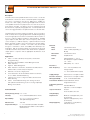
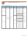
measuring
Insertion Paddle Wheel
Flow Meter / Monitor
•
monitoring
•
for Low Viscosity Liquids
analyzing
DOR
● Flow Range:
5.5 … 180 GPM to 25,000 … 800,000 GPM
● Flow Velocity Range: 1.0...33.0 ft/s
● pmax: 1160 PSI
● tmax: 300 °F
● Connection: 1½" NPT, 2" NPT Male, R 1½,
& R 2 Male for Pipe Sizes: 1½"...100"
● Linearity: ± 1.5% with Well Established
Flow Profile
● Body Material: Stainless Steel
● Outputs: Pulse, LCD Display,
Batching, Totalizing, 4 - 20mA, Switches
Order from:
03/2- 2015
C A Briggs Company
632 Davisville Road
Willow Grove, PA 19090
Phone: 215-784-9250; Fax: 215-784-0611
E-Mail: [email protected]
www.cabriggs.com
1.412.788.4890
[email protected]
www.koboldusa.com
Insertion Paddle Wheel Flow Meter / Monitor Model DOR
Description
The DOR series insertion paddle wheel flow sensor offers cost effective
measurement of the flow of water or water-like liquids in large pipes.
The sensor is inserted into the process piping via a suitable tee,
thread-o-let or half coupling. Flow through the pipe results in rotation
of the paddle wheel which is proportional to the flow velocity and to
the flowrate in the pipe. The DOR is much less expensive than full
bore flowmeters, especially in larger pipe sizes. Insertion paddle wheel
sensors are rugged and boast exceptional tolerance to dirt and solids.
The DOR features an all 316 L stainless steel body. The rotor is made of
PVDF or PEEK, with a long-life graphite/PTFE self-lubricating bearing.
It has an integral, precision insertion mechanism that allows insertion of
the rotor to a precise depth in the pipe for optimal readings. Available
signal outputs include NPN open collector frequency, and/or reed
contact frequency or millivolt frequency. Optional indicators include
battery powered totalizers and loop powered rate meter/totalizers
with outputs and batch controllers. The DOR-5 may be installed
through a 2" ball valve to allow serviceability with minimal process
interruption. With its symmetrical design, the DOR may also be used
for bi-directional flow measurement when fitted with the quadrature
output option in conjunction with an appropriate discriminator circuit
or display.
Materials
Body:
316L Stainless Steel
Rotor:
PVDF or PEEK (Depending on
Model)
Rotor Shaft:
316L Stainless Steel
Applications
Bearing:
Graphite/PTFE
●
Seals:
FKM (Standard): 5 … 300 °F
EPR (Ethylene Propylene Rubber):
-40 … 260 °F
NBR (Nitrile): -40 … 260 °F
●
●
●
●
●
●
●
HVAC: Hot and Cold Water, Fire Systems, and Thermal
Energy Monitoring
Municipal: Water Distribution, Water Management and
Water Treatment
Irrigation: Water Management
Water Treatment: Chlorination, Desalination and Mechanical
Filtration Plants, Chemical Injection Systems
Refineries: Fire and Cooling Systems
Power Generation: Boiler Feed Water, Steam Condensate,
Process Water and Water Balancing
Chemical: Process & Cooling Tower Water, Chemical and
Water Batching
Others: Cement Manufacturing, Flow Testing, Fire Truck
and Hydrant Flow Monitoring, Food Processing, Pulp/Paper,
Mining, and Fountains
Technical Details
Electronics
Max. Frequency:
73 ... 80 Hz (Reed Switch Output)
Supply Voltage:
See Electronics Comparison Table
Electronic Features:
See Electronics Comparison Table
Wiring (Standard):
10 Ft., 5 wire Shielded Cable
Transmission Distance: 3000 ft Maximum, without
Integrated Electronics
Cable Entry (Terminal
Box):
Standard: M20x1.5
Optional: 1/2" NPT via Adapter
Ingress Protection:
Velocity Range (Linear): 1.0 ... 33 ft/s
Linearity:
±1.5% w/Well Established Flow Profile
Repeatability:
±1% of f. s. at Factory Conditions
and Optimal Straight Runs
Max Pressure:
1160 PSI
Temperature Range:
5 … 212 °F Standard, See Max. Allowable
Media Temperature Table for Other Options
and Restrictions
220 ... 240 Hz (Hall Effect and
Voltage Output)
Straight Piping
Requirement:
Weight (Approx.):
IP 66/67
IP 68 w/Cable Connection
Minimum: 10xd (Upstream), 5xd
(Downstream)
Optimal: 25xd (Upstream), 10xd
(Downstream)
3.6 lb (DOR-4), 5.5 lb (DOR-5)
without Electronics
2
www.koboldusa.com
No responsibility taken for errors;
subject to change without prior notice.
Insertion Paddle Wheel Flow Meter / Monitor Model DOR
Electronic Options with LCD Display
Electrical Output Specifications
Model
Hall Effect Sensor Output (Fx, Nx, Qx)
The Hall Effect Sensor is a high resolution, solid state 3 wire device
providing an unsourced, open collector, NPN transistor output.
The term "unsourced" means that no voltage is applied to the
output from within the flowmeter. It must be pulled to a 'high' or
'on' state by 5 - 24VDC supplied from an external source, typically
the receiving instrument. The pulse output between signal and
-0V is a voltage square wave with the high level being the DC
voltage available at the open collector and the low level being
-0V. The receiving instrument must incorporate a pull up resistor
(typically greater than 10 kΩ) which ties the open collector to the
available DC voltage level when the Hall sensor is not energized.
When energized, the open collector output is pulled to ground
through the emitter (-0V). The power supply requirement is: 5 - 24
VDC, 20 mA max.
Voltage Pulse Output (Fx)
A self generating 2 wire voltage pulse output with 1.5V voltage
spike of approximately 10 microseconds duration is generated
with no dependence on rotor speed.
Reed Switch Pulse Output (Rx)
The reed switch output is a two wire normally open SPST voltage
free contact ideal for installations without power or for use in
hazardous area locations (simple apparatus) when Intrinsically
Safe (I.S.) philosophy is adopted. When using the reed switch
output, the liquid temperature must not change at a rate greater
than 18 ºF per minute. In general, the reed switch life will exceed
2 billion actuations when switching less than 5VDC at 10mA. The
voltage/current limits are: 30 VDC max, 200 mA max.
..Z1
..B1
Dual
Rate
Rate
Batch
Totalizer
Totalizer
Controller
yes
yes
yes
no
8 - 24 VDC
8 - 24 VDC
8 - 24 VDC
12 - 24 VDC
-Line 1 / no. of Digits
7.5 mm/5
9 mm/8
17 mm/6
9 mm/8
-Line 2 / no. of Digits
Power Source
Battery-powered
External (Required for
Output, Backlighting)
LCD Display
3.6 mm/8
–
7 mm/8
–
Selectable Units
yes
yes
yes
yes
Decimal Point
yes
yes
yes
yes
Subscripts Displayed
yes
yes
yes
yes
Accumulated Total
yes
yes
yes
yes
Resettable Total
yes
yes
yes
no
Linearization
no
yes
no
no
Rate Display
no
yes
yes
no
Backlighting
no
no
yes
no
Input Type
Unpowered Sensors
See display user manual
Powered Sensors
See display user manual
Outputs
4-20 mA (750 Ω)
no
yes
no
High/Low Flow Output
no
NPN/PNP
no
no
Batch End & Control
no
no
no
NPN/PNP
NPN/PNP
NPN/PNP
NPN
NPN/PNP
no
optional*
no
optional*
yes
yes
yes
yes
Cable Entries
2 x gland
3 x ½"NPT
3 x M16
3 x ½"NPT
Intrinsic Safe Option
upon req.l
upon req.
no
no
Pulse Output
no
Installation
IP 66/67
Standard: Meter mounted via stem
Mounting
Optional: Wall, pipe or panel mounting
Ambient Temperature
NPN Inductive Pick-up (Ex)
Inductive pick-up with non-magnetic rotor for applications with
high ferrous content liquids. The signal output is 3-wire, NPN
transistor. The power supply requirement is: 5 - 24 VDC, 20 mA max.
..Z7
Totalizer
Function
2 x SPDT Relays
Quadrature Pulse Output (Qx)
Two Hall-Effect sensors are arranged to give separate outputs out
of phase with one another. The Quadrature output is commonly
used to provide verification of output signal integrity or to measure
bi-directional flow in conjunction with an appropriate discriminator
circuit or display. The power supply requirement is: 8 - 24 VDC,
20 mA max.
..Z3
-4...176 °F (non-condensing)
* Replaces solid state outputs, consult factory for availability
DOR Series Nominal Flow Measuring Ranges
(Sch 40 Steel Pipe, 1...33 ft/s Fluid Velocity)
Line Size
(Sch. 40 Steel)
Nominal
Measuring
Range (GPM)
Line Size
(Sch. 40 Steel)
Nominal
Measuring
Range (GPM)
1-1/2"
6...210
10"
245...8,080
2"
10...345
12"
360...11,625
2-1/2"
15...490
14"
480...15,850
3"
25...760
16"
560...18,175
4"
40...1,300
18"
700...23,100
6"
90...2,975
20"
875...28,550
8"
160...5,170
24"
1,250...41,250
3
No responsibility taken for errors;
subject to change without prior notice.
www.koboldusa.com
Insertion Paddle Wheel Flow Meter / Monitor Model DOR
Order Details (Example: DOR-42 2 F N8 F6 Z3)
Model
Sealing
Material
Rotor/Shaft
Mechanical
Connection
DOR-42 Options
Output/
Electrical Connection
..F1.. =
..F2.. =
..N8.. = 1½" NPT
Male
..F3.. =
..F4.. =
..N9.. = 2" NPT
Male
DOR-42.. = Pipe Size
1½" ... 36"
..F5.. =
..F6.. =
..R8.. = R 1½
Male
..R9.. = R2 Male
..2.. =
PVDF/SS
(Max. 212 °F)
..4.. =
PEEK/SS
(Max. 300 °F)
..F.. = FKM
(Standard)
..N5*.. = NPN OC + Terminal Box
on Stem kit + High Temp.
Sensor
DOR-52.. = Pipe Size
2" ... 100"
DOR-52 Options
..N9.. = 2" NPT
Male
..00 = Frequency
Output
Only
..R1.. =
..R2.. =
..R3.. =
..R4.. =
..R5.. =
Reed Switch + 10' Cable
Reed Switch + 30' Cable
Reed Switch + 60' Cable
Reed Switch + 150' Cable
Reed Switch + Terminal
Box on Stem Kit
Only for Output
F6
..Q1.. =
..Q2.. =
..Q3.. =
..Q4.. =
..Q5.. =
2x NPN OC + 10' Cable
2x NPN OC + 30' Cable
2x NPN OC + 60' Cable
2x NPN OC + 150' Cable
2x NPN OC + Terminal
Box on Stem Kit
..Z1 = Dual
Totalizer
..E1.. =
Non-magnetic Rotor for
Ferrous Media, NPN,
10' Cable
Non-magnetic Rotor for
Ferrous Media, NPN,
30' Cable
Non-magnetic Rotor for
Ferrous Media, NPN,
60' Cable
Non-magnetic Rotor for
Ferrous Media, NPN,
150' Cable
Non-magnetic Rotor for
Ferrous Media, NPN,
Terminal Box on Stem Kit
..E.. = EPR
..N.. = NBR
NPN OC + 1.5V-Pulse +
10' Cable (Standard)
NPN OC + 1.5V-Pulse +
30' Cable
NPN OC + 1.5V-Pulse +
60' Cable
NPN OC + 1.5V-Pulse +
150' Cable
NPN OC + 1.5V-Pulse +
Terminal Box on Stem Kit
NPN OC + 1.5V-Pulse +
Integral Electronic on
Stem Kit
Electronics
..E2.. =
..R9.. = R2 Male
..E3.. =
..E4.. =
..E5.. =
..B1 = Batch
Controller
..Z3 = Rate/Dual
Totalizer
..Z7 = Rate/Dual
Totalizer
* Only available with PEEK rotor and sealing material: "F"
4
www.koboldusa.com
No responsibility taken for errors;
subject to change without prior notice.
Insertion Paddle Wheel Flow Meter / Monitor Model DOR
Process Temperature Limits
with Rotor and Output Options*
Rotor
Through-Valve Installation for DOR-52 series
Max. Media
Temperature
PVDF
212 °F
PEEK
300 °F
Output Type
E1 - E4
185 °F
F1 -F4
R1 - R4
Q1 - Q4
212 °F/260°F*
F5, F6, R5
260 °F*
N5
300 °F*
Model DOR-52
Ball or gate valve:
female 2" NPT or R2
connection
NOTE: Minimum
internal diameter
to be 44.0 mm
*
Must use PEEK rotor for all output options with
media temperatures > 212 °F. Additionally, be sure
to select an appropriate seal material suitable for
both media compatibility and the maximum media
temperature.
2" NPT or R2
Nipple
Typical DOR Installation
Female 2" NPT or R2
Threadolet
NOTE: Minimum internal
diameter to be 44.0 mm
Insertion Depth =
1/8 of Pipe
Inner Diameter
DOR Upstream/Downstream Straight Piping Requirements
Major obstructions, such as
pumps, valves, reducers or strainers
must be kept well outside of the
required straight run pipe sections
10 pipe dia. Minimum
25 pipe dia. Preferred
5 pipe dia. Minimum
10 pipe dia. Preferred
FLOW
5
No responsibility taken for errors;
subject to change without prior notice.
www.koboldusa.com
Insertion Paddle Wheel Flow Meter / Monitor Model DOR
Dimensions (mm)
TERMINAL
BOX
91
Z1
Z
7
Z5
85
113
Z3/B1
122
62.5
H
B
DOR-52
1-½" or 2" NPT/R2
2" NPT/R2
B
198
444
Configuration
H
H
Terminal Box
385
869
Z1
394
880
Z3/B1
415
900
Z7
380
865
13
DOR-42
ØA
ØA
All dimensions in mm, ± 2 mm
6
www.koboldusa.com
No responsibility taken for errors;
subject to change without prior notice.