1
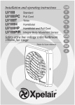
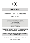
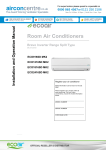
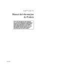
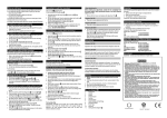
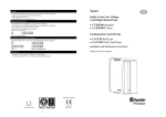
airooncentre.co.uk
The Ventilation Specialists
Quick Order Hotline
0800 865 4567
þ Guaranteed Low Prices
þ Huge Stock Available
þ Xpelair Stockist
or 0121 250 2186
Mon-Fri: 8:30am - 6:30pm | Sat & Sun: 11am - 5pm
F
D
uk
GB
.c
o.
Installation and maintenance instructions
DX100
Standard
DX100PC Pull Cord
DX100T Timer
DX100H Humidistat
DX100HP Humidistat and Pull Cord
DX100PIR Integral Body Movement Sensor
DX100VTD Delay Timer
Toilet/Bathroom 100mm/4" Fan Range
irc
tre
I
S
GR
N
SE
on
ce
n
Retain for future reference
NL
A
®
airooncentre.co.uk
The Ventilation Specialists
Quick Order Hotline
0800 865 4567
þ Guaranteed Low Prices
þ Huge Stock Available
þ Xpelair Stockist
or 0121 250 2186
Mon-Fri: 8:30am - 6:30pm | Sat & Sun: 11am - 5pm
D
tre
.c
o.
uk
A
DX100PIR
E
on
ce
n
m
5m
12
F
C
G
mm
2
5
11
irc
B
airooncentre.co.uk
The Ventilation Specialists
Quick Order Hotline
0800 865 4567
þ Guaranteed Low Prices
þ Huge Stock Available
þ Xpelair Stockist
or 0121 250 2186
Mon-Fri: 8:30am - 6:30pm | Sat & Sun: 11am - 5pm
J
tre
.c
o.
DX100H & DX100HP
uk
H
K
on
ce
n
I
irc
DX100T
DX100PIR
L
3
airooncentre.co.uk
The Ventilation Specialists
Quick Order Hotline
0800 865 4567
þ Guaranteed Low Prices
þ Huge Stock Available
þ Xpelair Stockist
or 0121 250 2186
Mon-Fri: 8:30am - 6:30pm | Sat & Sun: 11am - 5pm
Please leave this leaflet
with the fan for the
benefit of the user
What the installer will need
THESE APPLIANCES ARE DOUBLE
INSULATED AND DO NOT REQUIRE AN
EARTH CONNECTION.
• A double pole isolating switch with a minimum
contact gap of 3mm (wall or ceiling mounted).
• If metal switch boxes are used, earthing
regulations must be followed.
• Suitably rated 2-core cable (DX100,
uk
These appliances are intended for connection to
fixed wiring. Check that the electrical rating shown
on each fan matches the mains supply.
DX100PC, DX100HP and DX100PIR).
All installations must be supervised by a qualified
electrician. Installations and wiring must conform
to current IEE Regulations (UK), local or
appropriate regulations (other countries).
• Suitably rated 3-core cable (DX100T, DX100H
If you have any queries before installing these
products or after they have been installed, call
the Xpelair Technical Hotline
+44 (0) 8709 000430. Our engineers are there to
help you during normal office hours (UK only)
and may be faxed at all other times on
+44 (0) 8709 000530.
• A wall or ceiling on/off switch with built-in
Customers outside the UK should contact your
local Xpelair distributor.
Description
and DX100VTD).
.c
o.
Xpelair
Toilet/Bathroom
Fans DX100,
DX100PC, DX100T,
DX100H, DX100HP
DX100PIR &
DX100VTD
installation &
operating
instructions
Installing the fan
• 3mm electrician's screwdriver and no.1 or 2
Pozdriv screwdrivers.
indicator light (DX100, DX100T, and
DX100VTD).
tre
GB
Xpelair fans have the following features:
• Universal mounting kit allows window/ wall
from water ingress, a condensation trap
(Xpelair no. XCT100) must be fitted as
close as possible to the fan in all situations
where any section of the duct work is
positioned higher than the fan itself.
If wall mounting the fan, you will also need
• Masonry drill, hammer & chisel (or core drill
equipment if available).
• Mortar to make good the hole if required.
on
ce
n
panel/ ventilation shaft/ ceiling mounting
options.
• To prevent a possible hazardous situation
• You will need a window pane between 3mm
• Operate the fan using an on/off switch
• Do not install in glass 3mm thick if the window
DX100PC
• If installing in sealed double glazing, a
DX100
(not supplied).
•
Operate the fan using integral pull cord.
DX100T
• Built-in timer automatically operates fan for a
preset delay of up to 30 minutes.
DX100H
•
Operates either when triggered automatically
by the humidity sensor or when turned on at
the on/off switch (light indicates when fan is
operating in manual mode).
DX100HP
• Operates either when triggered automatically
by the humidity sensor or when turned on
using the integral pull cord switch (light
indicates when fan is operating in manual
mode). Built-in timer automatically operates
fan for a preset delay of up to 20 minutes.
irc
DX100PIR
4
If window mounting the fan
• Single speed extraction
• An integral body movement sensor operates
the fan as long as movement is detected.
Built-in timer automatically operates fan for a
preset delay of up to 20 minutes.
DX100VTD
• Operate the fan using the on/off switch (not
supplied). The fan will not start for
approximately 2.5 minutes (+/- 27%).
After this time, the fan will operate. When the
fan is switched off, it will continue to operate
for approximately 7.5 minutes (+/- 27%).
and 6mm thick (preferably 4mm).
pane area is more than 0.2sq.m.
specially manufactured unit should be
obtained from the glazing manufacturer. You
will also require a special kit, Xpelair Cat. ref.
DXDG.
• If installing in sash windows, you should
mount the fan in the upper window. Secure the
upper sash in the closed position and fit stops
just below the level of the fan, to prevent
damaging it when the sash is raised.
• If installing in a panel which is between 9mm
and 46mm thick, you will need a special kit,
Xpelair Cat. ref. DXDG. Do not install these
fans in a panel which is more than 46mm
thick.
If ceiling mounting the fan
You will need to use the appropriate ancillaries
for termination. These items are available from
Xpelair.
1. WT10 - Termination ducting kit.
2. CFWG100 - Soffit board termination grille
(white or brown).
3. FD100 / 3 and FD100 / 6 - Flexible ducting.
Where to locate the fan
• Locate it as high as possible.
• At least 110mm from the edges of the
mounting surface to the centre of the hole.
• As far away as possible from and opposite to
the main source of air replacement to ensure
airooncentre.co.uk
The Ventilation Specialists
Quick Order Hotline
0800 865 4567
þ Guaranteed Low Prices
þ Huge Stock Available
þ Xpelair Stockist
or 0121 250 2186
Mon-Fri: 8:30am - 6:30pm | Sat & Sun: 11am - 5pm
to exceed 50˚C.
• If installed in a kitchen fans must not be
mounted immediately above a cooker hob,
or eye level grill.
• If installing in a room containing a fuel
• Exhaust air must not be discharged into a
flue used for exhausting of fumes from
appliances supplied with energy other than
electric. Requirements of all authorities
concerned must be observed for exhaust
air discharge and intake flow rates.
• When intended for use in possible
Preparing the hole
If working above ground floor level,
appropriate safety precautions must be
observed.
WARNING: EYE PROTECTION MUST BE
WORN DURING ALL DRILLING AND
CHISELLING OPERATIONS.
If installing in a wall
1. Check there are no buried pipes or cables
in the wall or obstructions on the outside
e.g. electricity, gas, water.
If in doubt, seek professional advise.
2. Mark on the wall the centre of the duct hole.
on
ce
n
chemical corrosive atmospheres, consult
out Technical Service Department. (For
overseas markets contact your local
Xpelair distributor).
WARNING : CHILDREN SHOULD NOT PLAY WITH
THE APPLIANCE AND ENSURE THAT YOUNG
CHILDREN AND THE INFIRM ARE SUPERVISED
tre
burning device which has a non-balanced
flue, it is the installer's responsibility to
ensure that there is enough replacement
air to prevent fumes being drawn down the
flue when the fan is operating up to
maximum extract.
Refer to Building Regulations for specific
requirements.
These models are permanently connected to the
supply and operation is controlled by a remote
switch. They should be directly wired to the
supply through an approved 10amp wall mounted
surface switch with at least 3mm clearance
between contacts.
uk
•
• Not where ambient temperatures are likely
flexible 2-core cable complete with 3 pin plug for
insertion into an approved 10 amp GPO or
directly wired through an approved 10A wallmounted surface switch with at least 3mm
clearance between contacts.
For Australia only (DX100T, DX100H & DX100VTD)
.c
o.
airflow across the room (e.g. opposite the
internal doorway).
Near the source of steam or odours.
• DX100PIR Only - Siting must ensure
detection of movement. Care should be
taken to avoid obstruction that may affect
detection beams A .
Installing the isolating switch and cables
1. Check that the electrical rating shown inside
the back plate matches your mains supply.
2. Check there are no buried pipes or cables
e.g. electricity, gas, water behind the switch
location (in the wall or above the ceiling).
If in doubt, seek professional advise.
3. Isolate the mains supply.
4. Lay in the cable from the isolating switch to
the fan location via the on/off switch
(if required).
5. Lay in the cable from the isolating switch to
the point of connection to the mains supply.
6. Install the isolating switch and on/off switch
(if required).
7. Make all connections within the isolating
switch and the on/off switch (if required).
irc
Note: on/off switch must be situated so that it
cannot be touched by persons making use of
the bath or shower.
WARNING : DO NOT MAKE ANY
CONNECTIONS TO THE ELECTRICAL
SUPPLY AT THIS STAGE.
For Australia only (DX100, DX100PC. DX100HP &
DX100PIR)
Connection to the supply can be made by a
3. Use this centre to mark a circle to suit the
wall duct (115mm diameter).
If core drill equipment is available:
4a.Use as directed by core drill manufacturer.
If core drill equipment is not available:
4b. Drill a centre hole right through the wall.
5. Cut the hole. Do not cut right through the
wall. (The recommended method is to drill a
series of holes, close together, around the
edge of the cutting line and remove the brick
between the holes with a chisel).
6. Go outside and cut a hole in the outer wall,
repeating the process described above.
7. Cut ducting to the correct length if required.
The wall tube supplied is telescopic and can
extend to 300mm maximum.
8. Fit the ducting. Ensure that the duct slopes
down away from the fan to allow drainage of
any incoming rain water to the outside.
9. Make good the hole. Allow the mortar to set
before continuing the fan installation.
If installing in a window or panel
1. Cut a hole, 125mm in diameter or if installing
in a window, obtain a ready cut pane.
2. The centre of the hole should be at least
110mm away from the edge of the panel or
pane of glass.
If installing in a ventilation shaft
1. Check there are no buried pipes or cables
in the ventilation shaft.
If in doubt, seek professional advise.
2. Cut a hole 110mm in diameter, in the side of
the shaft.
5
airooncentre.co.uk
The Ventilation Specialists
Quick Order Hotline
0800 865 4567
þ Guaranteed Low Prices
þ Huge Stock Available
þ Xpelair Stockist
or 0121 250 2186
Mon-Fri: 8:30am - 6:30pm | Sat & Sun: 11am - 5pm
Please leave this leaflet
with the fan for the
benefit of the user
If installing in a ceiling
1. Check there are no buried pipes or cables
in the ceiling/joists etc.
If in doubt, seek professional advise.
2. Cut a hole 115mm diameter.
Preparing the fan for installation
Remove the front cover by pressing the release
catches located on the sides of the unit with a
3mm screwdriver, whilst pulling the front cover
forward L
Mount the fan in the hole
uk
4. Fit ducting and condensation trap if
necessary, positioning condensation trap as
near to the fan as possible.
3. Making sure that the back draught shutter is
level, mark the positions of the two fixing
holes in the top right hand and bottom left
hand corners.
4. Remove the back draught from the wall duct.
5. Drill screw holes in these positions, and fit
the remaining wall plugs.
6. Holding open the top and bottom vanes, refit
the back draught shutter and fasten it to the
wall using the pointed and self-tapping
screws. Do not over tighten screws.
.c
o.
Xpelair
Toilet/Bathroom
Fans DX100,
DX100PC, DX100T,
DX100H, DX100HP
DX100PIR &
DX100VTD
installation &
operating
instructions
3. If the shaft has cavity wall, use the wall tube
to bridge the cavity.
7. Make sure that the vanes open
and shut freely.
If installing in window or panel
tre
GB
If working above ground floor level,
appropriate safety precautions must be
observed.
If installing in a wall, ceiling or vent
Mark the position of the back plate B
1. If installing in a window or panel no more
than 9mm thick, fit the white rubber gasket
around the edge of the hole. If installing in a
panel or sealed double glazing more than
9mm thick, a DXDG double glazing kit is
required. Follow the instructions supplied with
the special kit.
Attach the back draught shutter to the
spacer F
1. Holding the top and bottom vanes, insert the
back draught shutter 2 into the spacer 3 so
that the fixing holes in the top right and
bottom left hand corners match those on the
spacer.
on
ce
n
1. Hold the backplate so that the terminal block
faces you in the top left hand corner and the
lip points towards the hole.
Sealing the hole E
2. Carefully insert the lip into the wall
duct/ceiling or vent shaft.
3. Adjust the position of the back plate until it is
level.
4. Mark on the wall/ceiling or vent shaft the
positions of the three fixing holes in the back
plate.
5. Remove the back plate from the ducting.
6. Drill screw holes in these positions if
necessary, and fit wall plugs if necessary.
Mount the back plate C
1. Push the ribbed gasket (RG100) onto the lip
of the back plate 1
2. If installing in a ceiling or vent, push the
larger diameter piece of the telescopic wall
tube onto the ribbed gasket. Cut the tube to
the required length first, if necessary.
3. If wiring the fan from behind, remove
knockout. Feed the mains cable through the
cable entry hole in the back plate to the
terminals D.
irc
4. If wiring from above, leave the cable free to
be fitted into labyrinth.
6
5. Insert the lip of the back plate into the wall
duct/ceiling or vent shaft as before.
6. Fasten the back plate to the wall/ceiling or
vent shaft using appropriate fasteners. If
using screws, do not overtighten the
screws.
Mount the back draught shutter
1. Peel the backing from the foam strip supplied
and attach it around the outside of the lip on
the back draught shutter.
2. Go outside. Holding open the top and bottom
vanes, insert the lip into the wall duct.
2. Insert two of the flat ended self-tapping
screws provided and fasten the back draught
shutter to the spacer.
Mount the fan in the window G
1. Someone else must hold the back draught
shutter and spacer in position outside, with
the spacer against the glass.
2. Make sure that the two raised fixing holes in
the spacer are horizontal and are positioned
within the hole.
3. From inside, hold the back plate so that the
terminal block faces you in the top left hand
corner and the lip points towards that hole.
4. Align the holes in the back plate with those in
the spacer.
5. Insert two of the flat ended self-tapping
screws provided in the fixing holes, and
fasten the back plate to the spacer. Do not
overtighten the screws.
Wire the electrical connections
•
Make sure the mains supply is isolated,
1. Wire the fan as shown in H check the fan
model to diagram, feeding the cable between
the two raised pegs, if wiring from above, and
through labyrinth to terminal block.
2. Switch off the mains electrical supply and
remove fuses
3. Connect the cable from the isolating switch to
the electrical supply wiring.
•
For fixed wiring circuits the protective
airooncentre.co.uk
The Ventilation Specialists
Quick Order Hotline
0800 865 4567
þ Guaranteed Low Prices
þ Huge Stock Available
þ Xpelair Stockist
or 0121 250 2186
Mon-Fri: 8:30am - 6:30pm | Sat & Sun: 11am - 5pm
fuse for the appliance must not exceed
5A.
Cleaning (recommended once a month)
A QUALIFIED ELECTRICIAN MUST CARRY
OUT ALL CLEANING.
To adjust the over-run period turn the control
(T) clockwise to increase and anti-clockwise
to decrease.
DX100H & DX100HP only J
•
•
Humidity operation is factory set at approx.
70% Relative Humidity (RH), but can be
adjusted between 50% and 90% RH by
control(H).
Time delay is factory set at approx. 20 mins,
but can be adjusted by control (T).
Both controls are adjustable. Turn the controls
clockwise to increase time or RH, and anticlockwise to decrease.
DX100PIR only K
•
Adjust the overrun period with control (T).
Turn screwdriver clockwise to increase and
anti-clockwise to decrease.
All fans
•
3. To clean the front cover, either wipe it with a
damp, lint free cloth or wash it in warm soapy
water. Thoroughly dry the front cover and
refit.
4. Do not immerse the fan in water or other
liquids to clean any other parts of the fan.
5. Never use strong solvents to clean the fan.
6. Apart from cleaning, no other maintenance is
required.
Fit the front cover by aligning it square to the
duct and pushing it onto the duct until the
release catches snap into the slots on the
front cover.
on
ce
n
•
If wiring from above cut out the cable entry
slot marked on top of the front cover.
2. Remove the front cover by pressing the
release catches located on the sides at the
unit with a 3mm screwdriver, whilst pulling the
front cover forward L
tre
•
1. Before cleaning, isolate the fan completely
from the mains supply.
uk
•
.c
o.
DX100T only I
Using the fan
DX100 & DX100VTD only
•
Operate the fan using the on/off switch.
Repeat to switch off.
DX100PC only
•
Operate the fan by pulling and releasing the
cord. Repeat to switch off.
DX100T only
•
Operate the fan using the on/off switch. When
the switch is turned off, the fan continues to
operate for the adjustable time delay.
DX100H only
•
•
Manual mode: use the on/off switch. When
you switch off, the fan goes into automatic
mode after the time delay (light indicates
when fan is operating in manual mode).
Automatic mode: fan operates when relative
humidity rises and turns off again when
humidity drops.
DX100PIR only
The sensor detects movement in the room
and activates the fan. When movement is
sensed, the fan will run for a pre-set overrun
period and any further movement sensed will
re-start the sequence. This ensures that the
room is only ventilated during and
immediately after use. When the fan is first
installed there will be a stabilising period
of approximately five minutes. During this
time the fan will run for up to two minutes.
irc
•
7
airooncentre.co.uk
The Ventilation Specialists
Quick Order Hotline
0800 865 4567
þ Guaranteed Low Prices
þ Huge Stock Available
þ Xpelair Stockist
or 0121 250 2186
Mon-Fri: 8:30am - 6:30pm | Sat & Sun: 11am - 5pm
Notes
irc
on
ce
n
tre
.c
o.
uk
DX100,
DX100PC,
DX100T, DX100H,
DX100HP,
DX100PIR &
DX100VTD
54
airooncentre.co.uk
The Ventilation Specialists
Quick Order Hotline
0800 865 4567
þ Guaranteed Low Prices
þ Huge Stock Available
þ Xpelair Stockist
or 0121 250 2186
Mon-Fri: 8:30am - 6:30pm | Sat & Sun: 11am - 5pm
Do's and dont's
uk
• Do read all the instruction leaflet before commencing installation.
• Do install each fan with a double pole isolating switch with a contact gap of 3mm in
each pole.
• Do make sure the mains supply is switched off before attempting to make electrical
connections or carry out any maintenance or cleaning
• Don't install this fan in any window/panel which is less than 4mm thick.
Customers outside UK - see international below.
• UK: The fan is guaranteed against defects for 3 years from the date of purchase.
• Please keep your purchase receipt.
• If you have any problems, contact Xpelair's Head Office at the address shown below.
Technical advice and service
Please ask for details:
• By telephone on Techline:
• By fax on Techfax:
• At the address below
tre
Customers outside UK - see international below.
UK: Xpelair have a comprehensive range of services including:
• Free technical advice help-desk from Engineers on all aspects of ventilation.
• Free design service, quotations and site surveys.
• Service and maintenance contracts to suit all requirements.
.c
o.
Guarantee
+44 (0) 8709 000430
+44 (0) 8709 000530
Head Office, UK Sales Office and Spares
Applied Energy Products Ltd, Morley Way, Peterborough, PE2 9JJ England
+44 (0) 1733 456789
+44 (0) 1733 310606
+44 (0) 8709 000420
Sales/Spares Faxline:
http:\\www.xpelair.co.uk
+44 (0) 8709 000520
on
ce
n
Telephone:
Fax:
Sales/Spares Hotline:
International
irc
• Guarantee: Contact your local distributor or Xpelair direct for details.
• Technical Advice and Service: Contact your local Xpelair distributor.
Part No. 567202501
(Revision C)