1
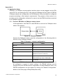
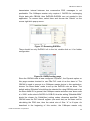
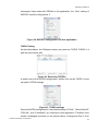
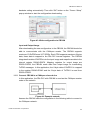
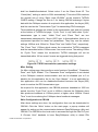
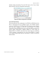
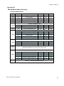
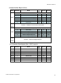
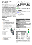
CBCAN CANopen Communication Board User’s Manual V1.0 07 Nov. 2011 FATEK Automation Corporation CBCAN User Manual Table of Contents Table of Contents ............................................................................................ 2 Tables.............................................................................................................. 4 Figures............................................................................................................. 5 1. Overview .................................................................................................... 7 2. Specifications ............................................................................................. 7 3. Installation and Wiring ................................................................................ 8 4. PLC Application Interface........................................................................... 9 4.1 Communication interface area ............................................................ 9 4.2 Parameter data area ........................................................................... 9 4.3 Process data area ............................................................................... 9 4.4 Module status area............................................................................ 10 5. LED Indicators.......................................................................................... 11 6. EasyCANopener Software Operations ..................................................... 12 6.1 PLC connection................................................................................. 13 6.2 Configuration setup ........................................................................... 13 6.2.1 Create new configurations........................................................ 13 6.2.2 Save configurations to files ...................................................... 19 6.2.3 Open old configuration files...................................................... 19 6.2.4 Read CBCAN Board configurations ......................................... 19 6.2.5 Write configurations to CBCAN Board ..................................... 20 6.2.6 Generate EDS files .................................................................. 20 6.2.7 End configuration setup ........................................................... 21 6.3 SDO Service ..................................................................................... 21 6.3.1 SDO Read................................................................................ 21 6.3.2 SDO Write ................................................................................ 22 6.3.3 SDO Batch ............................................................................... 22 6.4 PLC remote monitoring service ......................................................... 24 6.4.1 Open service ............................................................................ 25 6.4.2 Run service .............................................................................. 25 6.5 NMT Services.................................................................................... 26 6.6 CBCAN Firmware Update ................................................................. 26 FATEK Automation Corporation 2 CBCAN User Manual 6.6.1 Select firmware files ................................................................. 27 6.6.2 Start firmware update ............................................................... 27 6.7 End operations .................................................................................. 27 Appendix A .................................................................................................... 28 1.1 Application Notes .............................................................................. 28 1.1.1 Connect CBCAN to a CANopen master device........................ 28 1.1.2 Connect CBCAN to a CANopen slave device .......................... 33 Appendix B .................................................................................................... 40 CBCAN Board Object Dictionary .............................................................. 40 FATEK Automation Corporation 3 CBCAN User Manual Tables Table 1: CBCAN specification ...........................................................................................................7 Table 2: Definition of the pinning for the CBCAN connector ........................................................8 Table 3: Process data area ................................................................................................................9 Table 4: Module status area ............................................................................................................10 Table 5: Run LED .............................................................................................................................. 11 Table 6: ERR LED ............................................................................................................................. 11 Table 7: Run LED – Single status indicator mode........................................................................12 Table 8: Example – network configuration ....................................................................................28 Table 9: Example - network configuration .....................................................................................34 FATEK Automation Corporation 4 CBCAN User Manual Figures Figure 1: CBCAN Top View ...............................................................................................................8 Figure 2: FBs Top View ......................................................................................................................8 Figure 3: CANopen line termination .................................................................................................8 Figure 4: Term jumper location..........................................................................................................9 Figure 5: Indicator status and flash rate ........................................................................................ 11 Figure 6: EasyCANOpener main page ..........................................................................................12 Figure 7: Comm. setup.....................................................................................................................13 Figure 8: Configuration setup ..........................................................................................................13 Figure 9: RPDO setup page ............................................................................................................14 Figure 10: RPDO pop-up menu ......................................................................................................14 Figure 11: Edit RXPDO ....................................................................................................................15 Figure 12 Transmission type ...........................................................................................................16 Figure 13: TXPDO setup page........................................................................................................17 Figure 14: Misc. setup page ............................................................................................................18 Figure 15 Read configuration comm. setup ..................................................................................19 Figure 16: Node scan page .............................................................................................................20 Figure 17: Search result window ....................................................................................................20 Figure 18: Generate EDS file ..........................................................................................................20 Figure 19: SDO service page ..........................................................................................................21 Figure 20: SDO read page...............................................................................................................21 Figure 21: SDO write page ..............................................................................................................22 Figure 22: SDO batch page.............................................................................................................22 Figure 23: SDO batch setup page ..................................................................................................23 Figure 24: Pop-up menu for creating batch ..................................................................................23 Figure 25: Add a SDO command....................................................................................................23 Figure 26: PLC remote monitoring service ...................................................................................24 Figure 27: Gateway status window ................................................................................................25 Figure 28: Winproladder connection setup page .........................................................................26 Figure 29: NMT service ....................................................................................................................26 Figure 30: Firmware update ............................................................................................................26 Figure 31: Firmware information.....................................................................................................27 Figure 32: Example Network ...........................................................................................................28 Figure 33: Main page........................................................................................................................29 Figure 34: Module configuration page ...........................................................................................29 Figure 35: Node ID configuration....................................................................................................29 Figure 36: Baud Rate configuration ...............................................................................................29 Figure 37: Removing RXPDOs .......................................................................................................30 Figure 38: RXPDO setting page .....................................................................................................30 Figure 39: RXPDO1 configuration for this application.................................................................31 Figure 40: Removing TXPDOs........................................................................................................31 Figure 41: TXPDO settings..............................................................................................................31 Figure 42: TXPDO transmission parameters settings .................................................................32 Figure 43: Write configuration to CBCAN......................................................................................33 Figure 44: Example network............................................................................................................33 Figure 45: Main page........................................................................................................................35 Figure 46: Module configuration page ...........................................................................................35 FATEK Automation Corporation 5 CBCAN User Manual Figure 47: Node ID configuration....................................................................................................35 Figure 48: Baud Rate configuration ...............................................................................................35 Figure 49: Removing RXPDOs .......................................................................................................36 Figure 50: RXPDO setting page .....................................................................................................36 Figure 51: RXPDO1 configuration for this application.................................................................37 Figure 52: Removing TXPDOs........................................................................................................37 Figure 53: TXPDO settings..............................................................................................................37 Figure 54: TXPDO transmission parameters settings .................................................................38 Figure 55: Write configuration to CBCAN......................................................................................39 FATEK Automation Corporation 6 CBCAN User Manual CBCAN Board User’s Manual 1. Overview The CBCAN board is the communication board of the FBs PLC series from FATEK. It can be directly mounted on the extension board slot of the CPU module without the additional space. With the CBCAN, the PLC can directly communicate with other devices connected to the CANopen network. CANopen is a CAN-based industrial protocol and is widely used in field applications, such as automatic controls for industrial machinery, automobile control systems, factory automation, medical equipment control, building automation, remote data collection and control, environmental monitoring and others. 2. Specifications Item Table 1: CBCAN specification Characteristics Compliance with PDO quantity SDO quantity CAN 2.0A , DS301 V4.02 RPDO 10, maximum TPDO 10, maximum Server 1 Client 1 Application Parameter Object 1,000 registers, maximum Sync Master Configurable sync. time period NMT Master Available via utility tool Time Stamp Consumer Error Control Heartbeat Communication Baud Rate 20K, 50K, 125K, 250K, 500K, 750K, 1M, programmable Configuration Remote operation Supported Tooling PC software EasyCANopener Method Modify via PLC communication port Remote PLC Programming Supported Vendor ID 2EF (Hexadecimal) Signal Terminal 3-pin spring terminal Electric Isolation Yes Voltage/Current 5V, 150mA Working Temperature 0-60C Storage Temperature -20-80C FATEK Automation Corporation 7 CBCAN User Manual 3. Installation and Wiring The CBCAN is a CANopen communication board for FBs series PLC. FBs PLCs provides an extension slot for installing optional communication boards. Figure 1: CBCAN Top View Figure 2: FBs Top View The CBCAN is connected to the CANopen network via a 3-pin spring style connector. Table 2: Definition of the pinning for the CBCAN connector Pin Signal Description 1 CAN_H CAN_H bus line (dominant high) 2 CAN_L CAN_L bus line (dominant low) 3 CAN_GND Ground / 0V / V- Figure 3: CANopen line termination Normally for a node located at either left or right most side of network, a 120Ω 1/4W line termination resistor should be connected between CAN_H and CAN_L terminal pins as shown in above picture to ensure the signal quality, but for CBCAN, there’s an easier way to implement the same function - short the jumper (JP4) labeled “Term” inside the CBCAN module. The following picture shows the “Term” jumper location of CBCAN. FATEK Automation Corporation 8 CBCAN User Manual Figure 4: Term jumper location 4. PLC Application Interface The PLC CPU communicates with the CBCAN board via its internal registers. These registers basically fall into the following areas: 4.1 Communication interface area In this area, there are 70 reserved registers, ranging from R3700-R3769. These registers shall be reserved for internal system operation and CAN NOT be used for user’s applications since the configuration tool EasyCANopener communicates with the CBCAN through this area. 4.2 Parameter data area The size of this area is configurable up to 1000 registers. From the network point of view, these registers in this area act as objects in that control node. These registers can be addressed by their indexes and sub-indexes, thus they can be accessed by SDO services. With this function, users can change/adjust parameters of users’ applications over network easily during system installation in the field. 4.3 Process data area There are 80 registers in this area, ranging from R3600-R3679. The real-time data of the PLC is exchanged with other nodes on the network via this area. Sequence 1 2 3 4 5 ~ 40 41 42 43 44 45 ~ 80 FATEK Automation Corporation Table 3: Process data area Item Function Word #1 Word #2 TPDO1 Word #3 Word #4 TPDO2 ~ TPDO10 Word #1 Word #2 RPDO1 Word #3 Word #4 RPDO2 ~ RPDO10 Register R3600 R3601 R3602 R3603 R3604 ~ R3639 R3640 R3641 R3643 R3644 R3645 ~ R3679 9 CBCAN User Manual The data length (0-4, with one register size per unit) of each PDO (Process Data Object) is configurable. When the data length is smaller than 4, registers in the front will be used first. For example, if the length of TPDO1 is 2, only the first two registers R3600 and R3601 will be used. The starting register number of each PDO is fixed and will not be changed regardless of the preceding PDO length settings. Any unoccupied registers in this range can be free to use by applications. 4.4 Module status area Table 4: Module status area Sequence Register 1 R3680 Module Status 2 R3681 RPDO Status 3 R3682 4 R3683 5 R3684 6 R3685 Node 48-63 7 R3686 Node 64-79 8 R3687 Node 80-95 9 R3688 Node 96-101 10 R3689 Node 102-127 11 R3690 Second (0-59) 12 R3691 Minute (0-59) 13 R3692 14 R3693 15 R3694 Month (1-12) 16 R3695 Year (2000-2099) FATEK Automation Corporation Heart beat status Time Stamp Function Low Byte: Bit 0 : =0, Normal =1,Stppped when excessive RX error occur while startup. Bit 1: Sync signal time-out, valid only if at least one TXPDO is configured in sync. mode. Bit 2: Reserved Bit 3: =1, CAN Rx error Bit 4: =1, CAN Tx error High Byte: Bit[15:8] CBCAN state. =0, init. =5, OPERATIONAL. =4, STOPPED. =127 PRE-OPERATIONAL Each bit represents the receiving status of each RPDO. When Bit =1, it means data update is normal. Bit #0 means RPDO1. Bit #9 means RPDO10. Nodes 1-15 When Bit #1=1, it means the heartbeat in Node 1 is detected. The detection cycle is determined by Heartbeat guard Time (refer 6.2.1.4). When Heartbeat guard time = 0, this register is not valid since CBCAN will not monitor heartbeat signals. Node 16-31 Node 32-47 Hour (0-23) Day (1-31) 10 CBCAN User Manual 5. LED Indicators If the check item “Single status indicator” (refer 6.2.1.4) is not checked, the RUN and ERR Led will be operated as follow: RUN LED (green) Indicator State Table 5: Run LED Node Operation State Single flash STOPPED On OPERATIONAL Blinking PRE-OPERATIONAL ERR LED (red)– Indicator State Table 6: ERR LED Error State Off No error Single flash Warning limit reach Triple flash Rcv. SYNC signal is time-out Quadruple flash Any one of expected RXPDOs is time-out On Bus off Figure 5: Indicator status and flash rate The RUN and ERR LED will be operated as follows when the check item “Single status indicator” is checked. RUN LED (green) – FATEK Automation Corporation 11 CBCAN User Manual Table 7: Run LED – Single status indicator mode Indicator State Node State On Normal network operation(OPERATIONAL) Blink (period = 1Sec.) Warning limit reach Blink (period = 5Sec.) Bus OFF Off Not OPERATIONAL state ERR LED – Always off. 6. EasyCANopener Software Operations Run EasyCANOpener.exe, and the main page will pop up as follows. Figure 6: EasyCANOpener main page Major functions of the software: Create, modify and set CBCAN configurations: Users can save configurations into a file to be used for duplication, storage and modification offline. SDO Service: Users can either access a single controller object directly or access multiple objects by batch operation. The batch contents can also be saved in files to be re-used in the future. PLC remote access bridge: The FBs PLC is usually connected to the Winproladder software via local serial port. When this function is enabled, the CBCAN can work as a remote programming gateway and Winproladder can connect to another FBs PLC at remote site through the CBCAN. NMT service: with a single operation, users can send “Start Remote”, “Enter PRE-OPERATIONAL”, “Reset Node”, “Reset Communication” and “Stop” commands to one single node or all nodes on the network. CBCAN firmware update: Users can update the firmware of the CBCAN Board on the PLC via the serial port. FATEK Automation Corporation 12 CBCAN User Manual 6.1 PLC connection Using this software to modify system settings of the PLC can only be done when the PLC is connected to the software via serial port, except for some offline operations such as creating or modifying configuration and SDO batch files. After the serial port is connected, click the “Comm. Port Setup” function key to set the serial port configuration as shown in the screen below. Figure 7: Comm. setup After the configuration is done, click the “Test” button to start the connection test. 6.2 Configuration setup Click the “Module Configuration” button on the main page to enter the Configuration Setup screen as shown below. Figure 8: Configuration setup 6.2.1 Create new configurations When entering the Configuration Setup screen, a new configuration file will be generated automatically and all parameters are in their default values. 6.2.1.1 Basic setup Functions at the top of configuration setup page as shown in the Figure 8 are described as follows: Baud Rate: This is the network operating speed. The default value is 250K bps. The range is 20K-1M bps. The same baud rate must be set for all node devices on the network; otherwise, they will not operate properly. Node ID: This ID is set to indicate the CBCAN’s node id on the CANopen FATEK Automation Corporation 13 CBCAN User Manual network and can be configured 1-127 or “Dynamic”. When it is set to “Dynamic”, the node ID will be configured with the same ID as the ID of the PLC CPU module. The advantage of using “Dynamic” is to prevent different CBCANs from using the same ID and causing conflicts, thus each node ID will be unique. Otherwise, the CBCAN will not be able to communicate with other nodes on the CANopen network. The default value for this setting is Dynamic. 6.2.1.2 RPDO setup Click the RPDO tab to enter the receive process data object (RPDO) setup page as shown in the Figure 9 below. Figure 9: RPDO setup page The number in parentheses of the tab name represents the quantity of PDOs that has been defined. As shown in the Figure 9, four RXPDOs have been defined. The RPDO is configured by the popup menu as shown in the Figure 10 below. Figure 10: RPDO pop-up menu The functions in this popup menu are described below. Edit: Right-click on the PDO you want to edit to start the pop menu, and select Edit… from the menu. Or, simply double-click the PDO you want to edit to start the following screen. FATEK Automation Corporation 14 CBCAN User Manual Figure 11: Edit RXPDO From this screen, users can configure the communication object ID (COB-ID) and data length. Items as shown in the Figure 11 are described as follows. Dynamic option: A COB-ID can be a fixed value or a value changed with CPU node id. This option is valid only when the current Node ID is set to Dynamic. The COB-ID can be set by either from master or slave perspectives as follows: By Role: Basically, every PDO of the master and slave nodes on the network has a default independent COB-ID. The default setting of each node is assigned with four TXPDO COB-IDs and four RXPDO COB-IDs. By Value: Input a value between 181H and 5FFH. Size Setup: The size of the RXPDO can be set to one to four 16-bit words. Delete: Right-click the PDO you want to delete and select “Delete” from the pop menu to delete the PDO. Insert: Right-click any location where a PDO to be inserted and select “Insert” from the pop menu to start the PDO Edit screen. After the configuration on the popup menu is done, a new PDO will be inserted at the location addressed. Add: Right-click the screen to start the popup menu. Select “Add” to start the PDO Edit screen. After the configuration on the popup menu is done, a new PDO will be added at the end of the list. Up: Right-click the PDO to be moved up. Select “Up” on the popup menu to move the PDO to one position upward. Down: Right-click the PDO to be moved down. Select “Down” on the FATEK Automation Corporation 15 CBCAN User Manual popup menu to move the PDO to one position downward. Delete All: Right-click on the screen to start the pop menu. Select “Delete All” to delete all PDOs in the list. There is an additional item “Timeout Time” at the bottom of the RPDO setup page as shown in Figure 9: Timeout Time: This setting is used to indicate the deadline after the reception of an RPDO message. If RPDO messages are received properly within this interval, the corresponding bit of PLC internal register R3681 “RPDO status” will be set to 1. If not, the bit will be set to 0 to indicate the RPDO timeout event. The default value for this setting is 1.5 seconds. 6.2.1.3 TPDO setup The TPDO setup is similar to the RPDO’s; this section only described the difference between TPDO and RPDO setup. Please refer to the section 6.2.1.1 for those similar settings. There is one additional item “Transmission Type” added to the TXPDO Edit page. Figure 12 Transmission type Transmission Type: It indicates the transmission type of the TPDO. Async (asynchronous transmission): A TPDO is transmitted when the TPDO data is changed or event time is elapsed without any data change. After TPDO messages are transmitted, the end of the Inhibit Time must be reached before sending next TPDO message. With this function, users can prevent the communication bandwidth from being consumed by unexpected high frequency input signals. Sync. (synchronous transmission): Whenever the status change, the TPDO message will be transmitted immediately after the next SYNC message is received. ETime+Sync (Event Time + SYNC): It differs from the Sync. mode in one additional transmission condition. In this mode, TPDO messages are also transmitted immediately after the next SYNC message is FATEK Automation Corporation 16 CBCAN User Manual received even if the status is not change during pre-defined event time. Cyclic: TPDO messages are transmitted periodically in time with the cyclic time setting. Figure 13 shows the TXPDO setup page. Three general settings for TXPDO transmission type at the bottom of the setup page are described as follows. Figure 13: TXPDO setup page Inhibit Time: The minimum transmission time interval when TXPDO are transmitted in Async. mode. After the transmitting of TXPDO messages, the next TXPDO message will not be sent until the end of inhibit time even if the status is changed during the inhibit time period. The default value is 100ms. Event Time: The maximum transmission time interval when TXPDO are transmitted in Async. mode. After the transmitting of TXPDO messages, the next TXPDO message will be sent immediately after the end of event time even if the status is not changed during the event time period. The default value is 1 second. Cyclic Time: The transmission time interval used in the Cyclic mode. The default value is 2 seconds. 6.2.1.4 Miscellaneous Click the “Misc.” tab to edit miscellaneous setup as shown in the Figure 14 below. FATEK Automation Corporation 17 CBCAN User Manual Figure 14: Misc. setup page Heartbeat: This represents the existence of a node within a specific time interval. In normal circumstances, a node will send a heartbeat signal at a regular interval. Other nodes determine if this node is operating normally based on this signal. Cycle Time: This represents the regular interval the node sends the heartbeat signal. If the value is “0”, this means the heartbeat function is disabled. Guard Time: This represents the time criteria for a node to detect if the heartbeat of other nodes is normal. In general, individual nodes have individual cycle times, thus users should set different cycle times for different nodes. However, this system assumes that the cyclic time of all nodes are the same in order to simplify the configuration process. In this case, the value must be greater than the default value. Parameter Data: In general, there are usually some parameters that do not change frequently. These parameters can be mapped to the CANOpen objects through the SDO (Service Data Object) service for remote access over the network. Size: This setting is to indicate the quantity of the mapped registers. The maximum value is 1000. Start Address: This represents the start address of the mapped register. Only R-registers can be mapped as parameter registers. Sync. Master option: When this option is enabled (checked), the CBCAN will operate as the sync. master node which transmits synchronous messages. If this option is disabled and any TXPDO is configured in sync mode, the CBCAN will monitor sync messages produced by the sync master on the network. If the sync master does not generate the sync messages within the pre-defined sync timeout time, a timeout event will be generated (R3680 Bit1). FATEK Automation Corporation 18 CBCAN User Manual Sync. Time: When Sync master option is enabled, this value represents the interval of synchronous messages transmission. When Sync master option is disabled, this value represents the sync timeout time for sync messages monitoring. A longer timeout time than the sync messages interval shall be given for getting the monitoring mechanism works properly. 6.2.1.5 Commands By inputting commands via this function, users can make additional configurations for the CBCAN Board. 6.2.2 Save configurations to files Click the “Save…” or “Save As” button. The save configuration window will pop up. Input the name of the file to be saved and click the “Save” button to save the configurations. 6.2.3 Open old configuration files Click the “Open...” button. The open configuration file window will pop up. Click the button and select the configuration files that have been saved. Click the OK button to open the selected configuration file. 6.2.4 Read CBCAN Board configurations Click the “Read” button. The Comm.Setup window as shown below will pop up. Figure 15: Read configuration comm. setup The Baud Rate and Comm. Port are the parameters for the PC serial communication port. Node ID: This presents the ID (1-127) of the CBCAN node to be read. If Local Node is selected, the system will read the contents of the CBCAN which mounted on the local PLC connected to the PC directly. Scan button: Click this button to scan nodes on the network. The screen is shown below:. FATEK Automation Corporation 19 CBCAN User Manual Figure 16: Node scan page Search Range: By setting the search range, users can narrow the scan range to save more time. Start Node: The ID of the start node for the scan. End Node: The ID of the end node for the scan. Click the “Start Scan” button to start scanning. By clicking the “Stop Scan” button, users can end the scan immediately. The information of the searched modules as shown below will be listed in the window. Figure 17: Search result window Information shown in the Vendor ID and CBCAN Serial number can help users to select a module. Read Completion: After setting the above items, click the OK button to complete reading CBCAN Board configurations. 6.2.5 Write configurations to CBCAN Board The operations are similar to section 6.2.4. The only difference is the clicking of the “Write” button. Please refer to Section 6.2.4 for details. 6.2.6 Generate EDS files Select “Generate EDS...”. The Generate EDS File window will pop up. Figure 18: Generate EDS file Description: Additional descriptions of the EDS file. FATEK Automation Corporation 20 CBCAN User Manual Created By: The name of the author who creates the EDS file. The settings of two items above will be included in the EDS file. Click the “OK” button to finish creating the EDS file. 6.2.7 End configuration setup Click the “Close” button to exit the relevant configuration setup functions. 6.3 SDO Service Click the “Device Parameter Access” button on the main page to enter the SDO Service screen as shown below. The setup items are described below. Figure 19: SDO service page Node ID: This represents the ID of the node you want to access. Index: This represents the main index of the object. Sub-Index: This represents the sub-index of the object. 6.3.1 SDO Read Click the SDO Read tab to enter the SDO Service screen as shown below. Cyclic Read option: Select (check) this option to read SDO data repeatedly. This function is useful for observing the dynamic change of objects. Read button: Click the button to start reading SDO data. The results will be displayed in the window as shown below. Figure 20: SDO read page The value “4” in the Data Size item means that the size of the data is 4 bytes. The data content are given in decimal (10), hexadecimal (AH) and string type FATEK Automation Corporation 21 CBCAN User Manual (0xa 0x0 0x0 0x0). 6.3.2 SDO Write Click the SDO Write tab to enter the SDO Write service screen as shown below. Figure 21: SDO write page Data Type: This means the type of object data. At present, the system supports only Byte, Word and Dword data. Data: The value you want to input. Users can select data format from the pull-down list next to the box: Hex (hexadecimal) or Decimal. Write button: Click the button and start writing. An error window will pop up if there is any error. 6.3.3 SDO Batch By using the SDO Batch, a list of pre-defined multiple SDO commands can be sent out sequentially. It is very useful when multiple CBCAN modules need to be set up with similar configuration, thus users don’t need to configure all functions one by one. First, click the SDO Batch tab to enter the SDO Batch screen as shown below. Figure 22: SDO batch page Click on the SDO batch window as shown in Figure 22 to start SDO Batch editing below. FATEK Automation Corporation 22 CBCAN User Manual Figure 23: SDO batch setup page 6.3.3.1 Create batch contents After entering the SDO Batch service screen, there should be no batch contents. Then, users can create the batch content. The menu pops up as shown below. Figure 24: Pop-up menu for creating batch Add: Right-click the batch content window and select “Add” from the pop menu to start the following window. Figure 25: Add a SDO command Node ID: Select the ID of the node you want to write SDO data to. Index: Input the index value. Sub-Index: Input the sub-index value. Data Type: Select SDO data type: Byte, Word or Dword. Value: Input a value. Click the OK button to complete creation of the new batch content. Insert: Right-click the location where the batch command to be inserted and select “Insert” from the pop-up menu. Click the “OK” button to insert a new batch command in the specified location. Delete: Right-click the batch item you want to delete and select “Delete” FATEK Automation Corporation 23 CBCAN User Manual from the pop-up menu to delete the SDO command. Delete All: Right-click the batch content window and select “Delete All” from the pop-up menu to delete all batch commands. Edit: Right-click the batch item you want to edit and select “Edit” from the pop-up menu or double-click the command item to edit its content. Then, click the “OK” button to complete modifying the content. 6.3.3.2 Save batch contents Click “File” from the main menu at the top of the window and click “Save” or “Save As” from the pull-down to save the current batch contents in a file. 6.3.3.3 Read this batch file Click “File” from the main menu at the top of the window and click “Open” from the pull-down list to read the contents of the batch file. 6.3.3.4 Execute batch write First, select the “Write” option in the operation group. Then, click the “Execute” button to start batch write. SDO write commands will be sent out according to the contents in the batch window. 6.3.3.5 Execute batch read First, select the “Read” option in the operation group. Then, click the “Execute” button to start batch read. SDO read commands will be sent out according to the contents in the batch window. It differs from “batch write” in the read-back values will overwrite the original ones. 6.4 PLC remote monitoring service With this service, the ladder programming software Winproladder from Fatek can connect to the remote PLC equipped with the CBCAN Board via the PC serial port, thus ladder programs on the remote PLC can be modified locally through local PLC equipped with CBCAN module. Figure 26: PLC remote monitoring service FATEK Automation Corporation 24 CBCAN User Manual 6.4.1 Open service Click the “Remote Programming” button on the main page to enter the remote monitoring service screen as shown below. Figure 27: Gateway status window Items in the screen are described as follows: Remote Node ID: Input the ID of the node which you want to connect. Link Status: Auxiliary status. Packet Transmitted: The quantity of data packets transmitted to the remote PLC. Packet Received: The quantity of data packets received from the remote PLC. This service is completed through the local CBCAN module which operates as a gateway between the remote PLC and local Winproladder software. It is based on the TCP communication at port 500. Ready: When the system is ready for the service, the button is green. On Line: When the TCP network and application are linked, the button is green. 6.4.2 Run service Users must connect to port #500 of the local machine via TCP connection to subscribe the service. Therefore, an example of Winproladder settings is shown below: FATEK Automation Corporation 25 CBCAN User Manual Figure 28: Winproladder connection setup page As it is connected via the TCP communication, users can link up with the CANopen network with Ethernet from a remote site. 6.5 NMT Services Click the “NMT Service” button on the main page to enter the NMT Services screen as shown below. Figure 29: NMT service Node ID: Input the ID of the NMT slave node to be managed. Users can select either a single node (1-127) or all nodes. Service: The service includes: “Start Remote”, “Enter PRE_OPERATIONAL”, “Reset Node”, “Reset Communication”, “Stop” After the configuration is done, click the “Send Command” button to start NMT service. 6.6 CBCAN Firmware Update Click the “Firmware Update” button on the main page to enter the Firmware Update screen as shown below. Figure 30: Firmware update FATEK Automation Corporation 26 CBCAN User Manual Note. The CBCAN firmware version can be read from object index 4000H sub-index 1. File Name: Input the file name of the firmware to be updated. 6.6.1 Select firmware files Click the button to open the file selection window. After selecting the firmware file, press the “OK” button. The following confirmation dialog box will pop up. Figure 31: Firmware information The information of the corresponding firmware file will appear in this dialog box. 6.6.2 Start firmware update Click the “Start” button to start the firmware update. 6.7 End operations Click the “Exit” button on the main page to close EasyCANOpener utility. FATEK Automation Corporation 27 CBCAN User Manual Appendix A 1.1 Application Notes CBCAN is a CANopen communication interface which can be plugged into the FBs series PLC for connecting the PLC with external CANopen devices. Most of CBCAN CANopen objects are configurable via EzCANopener utility and shall be configured properly according to field network requirements. The purpose of this section is to provide a quick configuration reference for users to set up CBAN modules connected to a CANopen network. 1.1.1 Connect CBCAN to a CANopen master device In this application, the FBs PLC with CBCAN is used as the CANopen slave node on the network. Figure 32: Example Network Assume the CANopen master uses the configuration in the following table to connect to the CANopen network. Table 8: Example – network configuration Items Values Node ID 2 Baudrate 125K bps Sync. master Disabled Error control Heartbeat producer (1000 ms) Heartbeat consumer (1050 ms) Number of TxPDO 1 (3 words) Transmission type: Async. Mode (255) Number of RxPDO 1 (3 words) To connect CBCAN to the master, the node id and baudrate are first items to be configured in terms of master settings. All CBCAN settings can be configured via the CBCAN device configuration of EasyCANopener utility. The CBCAN configuration can be started by clicking the “Module Configuration” button on the main page of EasyCANopener utility. FATEK Automation Corporation 28 CBCAN User Manual Figure 33: Main page Figure 34: Module configuration page The master’s node id is 2, thus any other id from 1~127 can be assigned to CBCAN. Assume the FBs PLC uses id node 1, CBCAN node id can simply use PLC’s node id as its CANopen node id because the id is not 2. Choose “Dynamic” option to use PLC’s node id as the CBCAN’s CANope node id. Figure 35: Node ID configuration The “Baud Rate” setting is located next to the “Node ID”, choose 125K to set up CBCAN serial communication speed to 125 kbps. Figure 36: Baud Rate configuration RxPDO Setting The CANopen master uses transmission type 255 in this application, the PDO messages will only be transmitted whenever events are triggered. The “Timeout Time” setting is not important for this application since the FATEK Automation Corporation 29 CBCAN User Manual transmission interval between two consecutive PDO messages is not predictable. The CANopen master only requires 1 RxPDO for exchanging 6-byte data with CBCAN, thus RxPDO2~RxPDO4 are not needed in this application. To remove them, select them and choose the “Delete” on the mouse right click pop-up menu. Figure 37: Removing RXPDOs There should be only RxPDO1 left in the list, double click on it for further configuration. Figure 38: RXPDO setting page Since the CBCAN node id was configured “Dynamic”, the Dynamic option on this page remains checked to use FBs PLC node id as the slave id. The CBCAN is used to connect to a CANopen master device in this application, choose “As Slave Node” mode to set up the RxPDO’s role as slave. The default setting “$NodeId” should then be selected for using CBCAN node id as the Slave Node ID. In general, the CANopen master and slave use “slave node id + 200h” as the slave’s RxPDO1’s COB-ID, thus the setting “$NodeId+200h” should be chosen for CobId(Hex) setting unless otherwise specified. The CBCAN uses the PLC internal register (one-word size) as the base unit for calculating the PDO size, thus the actual size of Size “4” is 8 bytes. As described in the beginning of this section, the CANopen master only FATEK Automation Corporation 30 CBCAN User Manual exchanges 6-byte data with CBCAN in this application, the “Size” setting of RxPDO1 shall be configured as 3. Figure 39: RXPDO1 configuration for this application TxPDO Setting As described above, the CANopen master only uses one TxPDO, TxPDO 2~4 shall be removed as well. Figure 40: Removing TXPDOs A similar way to the RxPDO configuration, double click on the TxPDO1 to set up further TxPDO settings. Figure 41: TXPDO settings Same as RxPDO configurations, the default settings of “Role”, “Slave Node ID”, “PDO No”, and “CobId(Hex)” are required for this application. Therefore, they remain unchanged as shown on the picture above. Change the Size to 3 for FATEK Automation Corporation 31 CBCAN User Manual having CBCAN exchange 6 bytes data with the CANopen master. As required in this application, the Async.(255) shall be used as the “Transmission Type” for transmitting PDO messages. Three additional settings are related to the transmission type and are located at the bottom of TxPDOs list page. “Cyclic Time” is only valid when “Cyclic” transmission type is used. “Inhibit Time” and “Event Time” are two transmission parameters for “Async.(255)” type. In this application, there is no requirement specified for these two parameters. They may use the default settings 1000ms and 100ms for “Event Time” and “Inhibit Time”, respectively. The “Event Time” 1000ms which means the consecutive TxPDO messages shall be transmitted within 1000ms even if no event occurs. The setting 100ms for “Cyclic Time” means the consecutive TxPDO messages will not be transmitted within 100 ms even if events are triggered during that period. Figure 42: TXPDO transmission parameters settings Misc. Setting On Misc. setting page, there are three main functions “HeartBeat”, “Parameter Zone”, and “Sync. Master”. The “Parameter Zone” configuration is not related to the CANopen network communication and can be disabled (set to 0 to disable) for this application. As for the “Sync. Master”, it is not applicable for this application and can be disabled/unchecked because the Async.(255) mode is used as the PDO transmission type. Since the CANopen master produces heartbeat at 1000 ms period, the CBCAN “Guard Time” shall use a higher value than 1000 ms. In this example, “Guard Time” is set to the value 1050 ms for monitoring the CANopen master heartbeat messages. Likewise, the CBCAN “Cycle Time” shall use a lower value than the CANopen master’s consumer heartbeat time. Write Configuration to CBCAN After above settings are done, the configuration then can be downloaded to CBCAN. Click the “Write” button on the main page, a pop-up window will appear for setting up the communication between EasyCANopener utility and CBCAN. The CBCAN on the local node is accessed through the FBs PLC port 0. Choose “Auto” baudrate to have EasyCANopner utility to detect FBs FATEK Automation Corporation 32 CBCAN User Manual baudrate setting automatically. Then click “OK” button on the “Comm. Setup” pop-up window to start the configuration downloading. Figure 43: Write configuration to CBCAN Input and Output image After downloading the new configuration to the CBCAN, the CBCAN should be able to communicate with the CANopen master. The CBCAN supports maximum 10 RxPDOs and 10 TxPDOs. Each PDO supports maximum 8 bytes data, these data is mapped to the FBs PLC internal registers. The CBCAN integrates the data of RxPDOs into the input image and maps those data to the internal register R3640~R3679. Mapping registers for output image are R3600~R3639, the CBCAN reads data from output image for transmitting TxPDO messages. In this application, the 6-byte data of RxPDO1 is mapped to the register R3640~R3642 and the 6-byte data of TxPDO1 is read from R3600~R3602. 1.1.2 Connect CBCAN to a CANopen slave device In this application, the FBs PLC with CBCAN is used as the CANopen master node on the network. Figure 44: Example network Assume the CBCAN uses the configuration in the following table to connect to the CANopen network. FATEK Automation Corporation 33 CBCAN User Manual Table 9: Example - network configuration items Values Node ID 1 Slave Node ID 2 Baudrate 125K bps Sync. master Disabled Error control Heartbeat producer (1000 ms) Heartbeat consumer (1050 ms) Number of TxPDO 1 (3 Words) Transmission type: Async. Mode (255) Number of RxPDO 1 (3 Words) To set up CBCAN CANopen communication, the node id and baudrate are first items to be configured in terms of network requirements. All CBCAN settings can be configured via the CBCAN device configuration of EasyCANopener utility. The CBCAN configuration can be started by clicking the “Module Configuration” button on the main page of EasyCANopener utility. FATEK Automation Corporation 34 CBCAN User Manual Figure 45: Main page Figure 46: Module configuration page Assume the FBs PLC uses id node 1, CBCAN node id can simply use PLC’s node id as its CANopen node id because it is not 2. Choose “Dynamic” option to use PLC’s node id as the CBCAN’s CANope node id. Figure 47: Node ID configuration The “Baud Rate” setting is located next to the “Node ID”, choose 125K to set up CBCAN serial communication speed to 125k bps. Figure 48: Baud Rate configuration RxPDO Setting The network requires transmission type 255 in this application, the PDO messages will only be transmitted whenever events are triggered. The “Timeout Time” setting is not important for this application since the transmission interval between two consecutive PDO messages is not predictable. The CBCAN only requires 1 RxPDO for exchanging 6-byte data with the CANopen slave node, thus RxPDO2~RxPDO4 are not needed in this FATEK Automation Corporation 35 CBCAN User Manual application. To remove them, select them and choose the “Delete” on the mouse right click pop-up menu. Figure 49: Removing RXPDOs There should be only RxPDO1 left in the list, double click on it for further configuration. Figure 50: RXPDO setting page Since the CANopen slave device does not use the same id as CBCAN, it’s not necessary to enable “Dynamic” which uses FBs PLC node id as the CANopen slave node id. The CBCAN works as a master device in this application, choose “As Master Node” mode to set up the RxPDO’s role as a master. According to the network configuration required by this application, the slave device uses node id 2, thus value 2 is selected as the “Slave Node ID” setting. In general, the CANopen master uses “slave node id + 180h” as the RxPDO1’s COB-ID, thus the COB-ID shall set to “182h”. (Please also double check if the CANopen slave node uses the general rule to configure its PDO settings.) The CBCAN uses the PLC internal register (one-word size) as the base unit for calculating the PDO size, thus the actual size of Size “4” is 8 bytes. As described in the beginning of this section, the CBCAN only exchanges 6-byte data with the CANopen slave device, the “Size” setting of RxPDO1 shall be configured as 3. FATEK Automation Corporation 36 CBCAN User Manual Figure 51: RXPDO1 configuration for this application TxPDO Setting The CBCAN only requires one TxPDO to transmit 6-byte data to the slave device, TxPDO 2~4 are not needed and shall be removed for this application as well. Figure 52: Removing TXPDOs A similar way to the RxPDO configuration, double click on the TxPDO1 to set up further TxPDO settings. Figure 53: TXPDO settings Same as RxPDO configurations, the “Role” shall be set to “As Master Mode” and the CobId(Hex) is then changed to “$NodeId+200h” automatically. The “Slave Node ID” does not use the same node id of FBs PLC, “Dynamic” setting FATEK Automation Corporation 37 CBCAN User Manual shall be disabled/unchecked. Select value 2 as the Slave Node ID. The “CobId(Hex)” setting is switch to 202h automatically. This value 202h matches the general rule of using “Slave node ID+200h” as the master’s TxPDOs COB-ID setting. Change the Size to 3 for having CBCAN exchange 6 bytes data with the CANopen master. As required in this application, the Async.(255) shall be used as the “Transmission Type” for transmitting PDO messages. Three additional settings are related to the transmission type and are located at the bottom of TxPDOs list page. “Cyclic Time” is only valid when “Cyclic” transmission type is used. “Inhibit Time” and “Event Time” are two transmission parameters for “Async.(255)” type. In this application, there is no requirement specified for these two parameters. They may use the default settings 1000ms and 100ms for “Event Time” and “Inhibit Time”, respectively. The “Event Time” 1000ms which means the consecutive TxPDO messages shall be transmitted within 1000ms even if no event occurs. The setting 100ms for “Cyclic Time” means the consecutive TxPDO messages will not be transmitted within 100 ms even if events are triggered during that period. Figure 54: TXPDO transmission parameters settings Misc. Setting On Misc. setting page, there are three main functions “HeartBeat”, “Parameter Zone”, and “Sync. Master”. The “Parameter Zone” configuration is not related to the CANopen network communication and can be disabled (set to 0 to disable) for this application. As for the “Sync. Master”, it is not applicable for this application and can be disabled/unchecked because the Async.(255) mode is used as the PDO transmission type. As required for this application, the CBCAN produces heartbeat at 1000 ms period, thus the “Cycle Time” is set to 1000ms. Assume the CANopen slave also produces heartbeat at 1000ms period, a higher value 1050ms “Guard Time” is set for monitoring the CANopen slave heartbeat messages. Write Configuration to CBCAN After above settings are done, the configuration then can be downloaded to CBCAN. Click the “Write” button on the main page, a pop-up window will appear for setting up the communication between EasyCANopener utility and CBCAN. The CBCAN on the local node is accessed through the FBs PLC port 0. Choose “Auto” baudrate to have EasyCANopner utility to detect FBs FATEK Automation Corporation 38 CBCAN User Manual baudrate setting automatically. Then click “OK” button on the “Comm. Setup” pop-up window to start the configuration downloading. Figure 55: Write configuration to CBCAN Input and Output image After downloading the new configuration to the CBCAN, the CBCAN should be able to communicate with the CANopen devices. The CBCAN supports maximum 10 RxPDOs and 10 TxPDOs. Each PDO supports maximum 8 bytes data, these data is mapped to the FBs PLC internal registers. The CBCAN integrates the data of RxPDOs into the input image and maps those data to the internal register R3640~R3679. Mapping registers for output image are R3600~R3639, the CBCAN reads data from output image for transmitting TxPDO messages. In this application, the 6-byte data of RxPDO1 is mapped to the register R3640~R3642 and the 6-byte data of TxPDO1 is read from R3600~R3602. FATEK Automation Corporation 39 CBCAN User Manual Appendix B CBCAN Board Object Dictionary . Communication Object Index SubIndex Name Data Type Access Default 1000H 0 Equipment Type I32U R 0 1001H 0 Error Register I8U R 0 1005H 0 COB-ID of SYNC I32U R 80H 100CH 0 Guard Time I16U R 0 100DH 0 Life Time Factor I8U R 0 Consumer Heartbeat Time 1016H 1017H 0 Item Count I8U R 1 1 Consumer Heartbeat Time I32U R 1020 0 Producer Heartbeat Time I32U R 1000 Identity Object 1018H 0 Item Count I8U R 4 1 Vendor code I32U R 2EFH 2 Product Code I32U R 0 3 Revision No. I32U R 0 4 Serial No. I32U R 0 RXPDO1 Communication Parameters 1400H 0 Item Count I8U R 2 1 RXPDO1 COB-ID I32U R CFG 2 Transmission type I8U R 0xff 1401H~ 1409H RXPDO2~RXPDO10 Communication Parameters RXPDO1 Mapped Objects 1600H 0 Item Count I8U R 4 1 RXPDO1 Mapped Object #1 I32U R CFG 2 RXPDO1 Mapped Object #2 I32U R CFG 3 RXPDO1 Mapped Object #3 I32U R CFG 4 RXPDO1 Mapped Object #4 I32U R CFG 1601H~ 1609H FATEK Automation Corporation RXPDO2 ~ RXPDO10 Mapped Objects 40 CBCAN User Manual Communication Object (Cont.) Index SubIndex Data type Name Access Default TXPDO1 Communication Parameters 1800H 0 Item Count I8U R 5 1 TXPDO1 COB-ID I32U R CFG 2 TXPDO1 Transmission Type I32U R 0xff 3 TXPDO1 Inhibit Time I32U R CFG 4 Reserved - - - 5 Event Time I16U R CFG 1801H ~ 1809H TXPDO2 ~ TXPDO10 Communication Parameters TXPDO1 Mapped Objects 1A00H 0 Item Count I8U R 4 1 TXPDO1 Mapped Object #1 I32U R CFG 2 TXPDO1 Mapped Object #2 I32U R CFG 3 TXPDO1 Mapped Object #3 I32U R CFG 4 TXPDO1 Mapped Object #4 I32U R CFG Default 1A01H ~ 1A09H TXPDO2 ~ TXPDO10 Mapped Objects . PLC Parameter Zone Objects (Max. 1000 R register) Index SubIndex Name Date type Access 2000H 1 P Zone+0 WORD RW 2000H 2 P Zone+1 WORD RW 2000H n P Zone+n-1 . 2000H 100 P Zone+99 WORD RW 2001H 1 P Zone+100 WORD RW 2001H 2 P Zone+101 WORD RW ~ ~ ~ WORD RW 2009H 100 P Zone+999 WORD RW FATEK Automation Corporation 41 CBCAN User Manual . PLC Process Data Objects Index SubIndex Name Data type Access Map TXPDO process data 2010H 1 R3600 2 R3601 3 R3602 4 R3603 2011H ~ 2019H R I16U R R Yes R R3604~R3639 RXPDO process data 201AH 1 R3640 2 R3641 3 R3642 4 R3642 201BH ~ 2023H R I16U R R Yes R R3640~R3679 .Program Version Objects Index 4000H SubIndex Name Data type Access Default 0 Item Count I8U R 2 1 CBCAN Firmware version I32U R 2 Ladder software version I32U R Ladder software version is decided by R3696 of the PLC . Electron board Version Objects Index 4001H SubIndex Name Data type Access Default 0 Item Count I8U R 1 1 Electron board version I32U R FATEK Automation Corporation 42