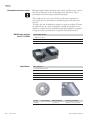
1
IEC CL40 - FL40 Series
User’s Manual
Analyze •
Detect •
Measure •
ControlTM
IEC CL40 - FL40 Series
User’s Manual
CL40 - FL40 Series
Carefully read this manual before operating your instrument.
Information contained in this document is the property of Thermo Electron Corporation; it may not be
duplicated or distribuited without the owner’s authorization.
The validity of the guarantee is subject to the observation of the instructions
and precautions described in this document.
Preface
MANUAL NUMBER
REV
ECR/ECN
DATE
DESCRIPTION
a
11290088
03/06
Initial release
Thermo Electron Corporation
BY
CL40 - FL40
i
Packing List
11210922
11210923
11210924
CL40,
CL40
CL40
230V 50/60 Hz
120V 60 Hz
100V 50/60 Hz
11210940
11210941
11210942
FL40
FL40
FL40
230V 50/60 Hz
120V 60 Hz
100V 50/60 Hz
11210926
11210927
11210928
11210929
CL40R
CL40R
CL40R
CL40R
230V 50/60 Hz
120V 60 Hz
100V 50 Hz
100V 60 Hz
11210943
11210944
11210945
11210946
FL40R
FL40R
FL40R
FL40R
230V 50/60 Hz
120V 60 Hz
100V 50 Hz
100V 60 Hz
Item number
Quantity
Check
Centrifuge
User manual
1
CE Declaration of compliance
1
Manual lid opening instructions
1
Imbalance protection instructions
1
64227001
Mains cord
1
26227005
Toolbox:
26339005
• Rotor removal tool
1
85241084
• Emergency unlooking tool
1
86000897
• 12 and 13 mm wrench
1
25055501
• 21 mm wrench
1
11290088
For missing parts call your nearest Thermo representative
ii
CL40 - FL40
Thermo Electron Corporation
WEEE Compliance
Great Britain
WEEE Compliance. This products is required to comply with the
European Union’s Waste Electrical & Electronic Equipment (WEEE)
Directive 2002/96EC. It is marked with the following symbol. Thermo
Electron has contracted with one or more recycling/disposal companies
in each EU Member State, and this products should be disposed of or
recycling through them. Further information on Thermo Electron’s
compliance with these Directives, the recyclers in your country, and
information on Thermo Electron products which may assist the detection of substances subject to the RoHS Directive are available at
www.thermo.com/WEEERoHS
Deutschland
WEEE Konformittät. Dieses Produkt muss die EU Waste Electrical &
Electronic Equipment (WEEE) Richtlinie 2002/96ECerfüllen. Das
Produkt ist durch folgendes Symbol gekennzeichnet. Thermo Electron
hat Vereinbarungen getroffen mit Verwertungs-/Entsorgungsanlagen in
allen EU-Mitgliederstaaten und dieses Produkt muss durch diese
Firmen widerverwetet oder entsorgt werden. Mehr Informationen über
die Einhaltung dieser Anweisungen durch Thermo Electron, die
Verwerter und Hinweise die Ihnen nützlich sein können, die Thermo
Electron Produkte zu identizfizieren, die unter diese RoHS Anweisung
fallen, finden Sie unter www.thermo.com/WEEERoHS
Italia
Conformità WEEE. Questo prodotto deve rispondere alla direttiva
dell’Unione Europea 2002/96EC in merito ai Rifiuti degli Apparecchi
Elettrici ed Elettronici (WEEE). È marcato col seguente simbolo.
Thermo Electron ha stipulato contratti con una o diverse società di
riciclaggio/smaltimento in ognuno degli Stati Membri Europei. Questo
prodotto verrà smaltito o riciclato tramite queste medesime. Ulteriori
informazioni sulla conformità di Thermo Electron con queste
Direttive, l’elenco delle ditte di riciclaggio nel Vostro paese e informazioni sui prodotti Thermo che possono essere utili alla rilevazione di
sostanze soggette alla Direttiva RoHS sono disponibili sul sito
www.thermo.com/WEEERoHS
Espana
WEEE. Este producto requiere cumplir con la Directiva 2002/96EC
WEEE (residuos de quipos electricos y electronicos). Este producto esta
marcado con el simbolo WEEE, como se describe. En cada Estado
Miembro de la Union Europea (EU), Thermo Electron ha contratado
con diversas companias para disponer y/o re-ciclar los residuos de equipos electricos y electronicos. Existe information adictional acerca de la
conformidad de Thermo Electron con esta Directiva, incluyendo los
nombres de las diversas companias autorizadas para disponer/recyclar
nuestros productos. Adicionalmente suministramos informacion acerca
Thermo Electron Corporation
CL40 - FL40
iii
WEEE Compliance
de los productos de Thermo Electron que puedes asistir en la deteccion
de substancian mensionades en la directiva RoHS, explicado en
www.thermo.com/WEEERoHS
France
iv
CL40 - FL40
Conformité WEEE. Ce produit doit être conforme à la directive européenne (2002/96EC) des Déchets d’Equipements Electriques et
Electroniques (DEEE). Il est merqué par le symbole suivant. Thermo
Electron s’est associé avec une ou plusieurs compagnies de recyclage
dans chaque état membre de l’union européenne et ce produit devrait
être collecté ou recyclé par celles-ci. Davantage d’informations sur la
conformité de Thermo Electron à ces directives, les recycleurs dans
votre pays et les informations sur les produits Thermo Electron qui
peuvent aider le détection des substances sujettes à la directive RoHS
sont disponibles sur www.thermo.com/WEEERoHS
Thermo Electron Corporation
Declaration of compliance
Declaration de conformite
We, Thermo Electron Industries S.A.S., Z.I. d’Aze Bellitourne 53200
CHATEAU-GONTIER, France, declare that the instrument defined
here below complies with the following European directives:
Declaration of compliance
Nous, Thermo Electron Industries S.A.S., Z.I. d’Aze Bellitourne 53200
CHATEAU-GONTIER, France, déclarons que le matériel désigné ciaprès est conforme aux directives européennes suivantes:
Konformitätserklärung
Wir, Thermo Electron Industries S.A.S. , Z.I. d'Aze Bellitourne 53200,
CHATEAU-GONTIER, France, erklären dass das hier beschriebene
Gerät sich in Übereinstimmung mit folgenden europäischen
Richtlinien befindet:
Declaración de conformidad
Nostros, Thermo Electron Industries S.A.S., Z.I. d’Aze Bellitourne
53200 CHATEAU-GONTIER, France, declaramos que el instrumento
bajo descrito está fabricado según las especificaciones establecidas por
las siguientes normas europeas:
Declaraçao de conformidade
Nós, Thermo Electron Industries S.A.S., Z.I. d’Aze Bellitourne 53200
CHATEAU-GONTIER, France, declaramos que o instrumento aqui
apresentado está de acordo com as normas européias abaixo listadas:
Dichiarazione di conformità
Noi, Thermo Electron Industries S.A.S., Z.I. d’Aze Bellitourne 53200
CHATEAU-GONTIER, France, dichiariamo che lo strumento sotto
descritto è conforme alle seguenti Direttive europee:
•
Machinery:
98 / 37 / CEE
•
Low voltage:
72 / 23 / CEE - 93 / 68 CEE
•
EMC:
89 / 336 CEE - 92 / 31 CEE - 93 / 68 CEE
•
Safety standard: EN 61010-1 - EN 61010-2-020
Château-Gontier, 28th June 2005
Managing Director
Christian Galiana
Thermo Electron Corporation
CL40 - FL40
v
Guarantee Terms
Thermo guarantees that this unit is free from defects in materials and
workmanship when it leaves the factory, and will replace or repair the
unit if it proves defective in normal use or during service for a period of
ONE YEAR from the delivery.
This guarantee is invalid if the unit is incorrectly used, poorly serviced
or neglected, mis-used or accidentally damaged.
There is no explicit guarantee other than as stated above.
vi
CL40 - FL40
Thermo Electron Corporation
For further information,
assistance or service
United States of America
Tel.: +1 800 522 77 46
Fax: +1 866 984 37 66
Canada or Latin America
Tel.: +1 800 522 77 46
Fax: +1 866 984 37 66
China (Shanghai)
Tel.: +86 21 68 65 45 88
Fax: +86 21 6445 7907, +86 21 6445 7830
India (Mumbai)
Tel.: +91 22 5542 9494
Fax: +91 22 5542 9495
Japan
Tel.: +81 454 53 9220
Fax:+ 81 454 53 9222
Other Asia-Pacific Countries
Tel.: +852 28 85 46 13
Austria
Tel.: +43 (1) 80 14 00
France
Tel.: +33 1 69 18 77 77
+33 2 28 03 20 00
Belgium
Tel.: +32 24 82 30 30
Italy
Tel.: +39 02 95 05 91
Netherlands
Tel.: +31 7 65 71 44 40
Russia/Cis
Tel.: +7 09 52 25 11 15
Spain and Portugal
Tel.: +34 9 32 23 31 54
Switzerland
Tel.: +41 (1) 4 54 12 12
United Kingdom and Ireland
Tel.: +44 87 06 09 92 03
Other Europe, Middle East, or Africa
Tel.: +49 61 8490 6940
Tel.: +33 2 2803 2000
In Other Countries:
Contact your local THERMO products distributor
or agent.
E-mail Technical Service Representative for
products at:
[email protected]
Visit our web site at: www.thermo.com
Germany
Tel.: +49 61 84 90 69 40
Fax: +49 61 03 40 81 012
Finland
Tel.: +35 89 32 91 00
Thermo Electron Corporation
CL40 - FL40
vii
Contents
viii
CL40 - FL40
Chapter 1
Use and Function........................................................................................1-1
User Manual......................................................................................1-1
Warning Symbols ..............................................................................1-1
Description ......................................................................................1-1
Refrigeration and Heating Systems....................................................1-2
Drive System ....................................................................................1-3
Safety Interlock System ....................................................................1-3
Imbalance Detection System ............................................................1-3
Relative Centrifugal Force ................................................................1-4
Chapter 2
Specifications ............................................................................................2-1
Dimensions and Weight ....................................................................2-1
Centrifugation Specifications ............................................................2-1
Electrical Specifications ....................................................................2-2
Chapter 3
Installation ..................................................................................................3-1
Environmental Conditions ................................................................3-1
Unpacking ........................................................................................3-1
Positioning ........................................................................................3-2
Mains Supply ....................................................................................3-2
Lid Opening and Rotor Checking ....................................................3-3
Manual Lid unlocking Procedure ......................................................3-3
Performance and Accessories ............................................................3-5
M4 Swing-out Rotor - Cat. N°: 11175338 ......................................3-5
Biocontainement Accessories ............................................................3-6
QG2.5 Swing-out Rotor - Cat. N°: 11175382..................................3-8
Angle Rotors ....................................................................................3-8
Glassware ........................................................................................3-10
Chapter 4
Instructions for Use....................................................................................4-1
Controls and Indicators ....................................................................4-1
Display Screens ................................................................................4-2
Control Panel Functions ..................................................................4-3
Control Panel Indicators ..................................................................4-4
Description of Certain Events with Respect to the Control System ..4-5
Preparing the First Run of the Day ..................................................4-7
Sample Loading ................................................................................4-7
Thermo Electron Corporation
Contents
Thermo Electron Corporation
Chapter 5
Hazards, Precautions and Limitations of Use ......................................5-1
IEC 1010-2-020................................................................................5-1
Cautions............................................................................................5-1
Speed Control ..................................................................................5-2
Operational Limitations ....................................................................5-2
Aerosol Risks ....................................................................................5-2
Chapter 6
Service and Maintenance ........................................................................6-1
Periodic Cleaning ..............................................................................6-1
Contamination Hazards ....................................................................6-1
Disinfection ......................................................................................6-2
Radioactive Decontamination ..........................................................6-2
Power Supply Circuit Breaker............................................................6-3
Rotor Removal ..................................................................................6-3
Trunnion Lubrication........................................................................6-3
Chemical Compatibility Table for Rotors, Tubes and Accessories......6-4
Chapter 7
Disposal of Product....................................................................................7-1
CL40 - FL40
ix
Chapter 1
User Manual
Use and Function
The user manual is part of the centrifuge, and contains important
information for your safety and for the best use of the equipment
Always keep the manual close to the appliance and in a safe place, so
that it is always available. Thermo strongly recommends that all users
read this manual carefully.
Warning Symbols
The following symbols are provided to help the operator take
advantage of the protection afforded by the equipment and to warn of
potential danger.
On the main switch, allows centrifuge to operate. ▲
On the main switch, disconnects the centrifuge from the main power
supply. ▲
Only authorized personnel can touch the parts close to this symbol
and, in any case, only after switching off the main power supply.
Coming in contact with high voltages could cause severe injuries. ▲
In this manual, this symbol means that you will find important
information for safety, which if unobserved could result in damage to
the appliance and/or harm to the operator. ▲
In this manual, this symbol means that you will find important
information about minimizing biological risk: if unobserved the result
could be harm to the operator. ▲
Description
The CL40 and FL40 centrifuges are designed for laboratory use.
They will separate the components of fluids into layers of varying
density by subjecting them to high forces.
Centrifugal force provided by the centrifuge can also be used to drive
solvents and low molecular weight solutes through the membrane of a
filtering device. Retained macrosolutes will therefore be found above
the membrane.
Relative Centrifugal Force (RCF) generated by a rotor is directly
Thermo Electron Corporation
CL40 - FL40
1-1
Chapter 1
Use and Function
proportional to its sedimentation useful radius and to the value of its
speed squared.
A control system permits the user, through an extremely intuitive
control panel, to set and control the speed, the g-force, the temperature
(on the thermostated and refrigerated versions) and the run time, as
well as to view different messages and warnings.
Refrigeration and
Heating Systems
The CL40 and FL40 are ventilated unit. A permanent air circulation
reduces the heat level in the bowl.
However the temperature in the bowl can reach 10 °C above the
ambient temperature after hours of continuous operation.
The CL40R and FL40R are equipped with a powerful refrigeration
system that allows samples to be processed at low temperature. The
refrigerant, R134a, is free of CFC (Chloro-Fluoro-Carbons) in
accordance with the Montreal Protocol directions for preservation of the
ozone layer in the atmosphere.
The actual temperature in the bowl is continuously displayed on the
front panel of the centrifuge. Under certain conditions (high speed,
long duration runs) the sample temperature can be higher than the
bowl temperature on the display. In this case, the user may compensate
manually after empirical determination of the temperature differential.
Condensation drain on
refrigerated units
The lid should remain closed when the refrigeration system is in use to
avoid condensation.
The centrifuge has a rubber hose that allows condensation to be
drained from the bowl. The drain hose exits at the back of the
machine. Near the drain hose you can find the following label:
To remove condensation, please follow this procedure:
1-2
CL40 - FL40
•
Switch off the centrifuge and disconnect the power.
•
Put a small basin under the hose.
•
Unplug the hose.
Thermo Electron Corporation
Chapter 1
Use and Function
•
Drain the centrifuge bowl.
•
Insert the plug back into the hose.
Attention Do not remove the plug from the drain hose during
centrifugation. ▲
Drive System
A three phase brushless motor drives the rotating equipment. The rotor
is contained in a sealed, armor plated centrifugation chamber.
The brushless motor requires no maintenance. A control system
ensures the correct drive speed, which is continuously monitored.
Safety Interlock
System
The CL40 and FL40 centrifuge series are equipped with an interlock
system that assures two basic safety features:
•
The run cannot be started if the lid is not correctly closed.
•
The centrifuge lid cannot be opened if the rotor is running.
The centrifuge will not operate until the lid is closed and latched in
place.
The lid remains latched until the rotor stops spinning. The lid access
lamp indicates when the rotor has stopped: consequently the handle on
the right hand side of the centrifuge can be used to open the lid.
If a power failure occurs, access to the samples in the centrifuge is
possible via a manual lid opening procedure (see appropriate
paragraph). For this operation a special tool (supplied with the
centrifuge) is required.
Bypass the interlock system only under emergency conditions as the
rotor could still be rotating.
Imbalance Detection
System
The CL40 and FL40 centrifuge series are equipped with a load
imbalance detector.
In case of excessive imbalance, the load imbalance indicator LED is
illuminated and the brake is applied immediately. The rotor will be
decelerated to rest in few seconds.
As soon as the motor stops, open the centrifuge and redistribute the
samples to produce an equal weight on diametrically opposite sides.
If the message persists, despite your efforts to balance the load, call
your Thermo Service representative.
Thermo Electron Corporation
CL40 - FL40
1-3
Chapter 1
Use and Function
Note Imbalance tolerance depends upon the rotor in use. The
centrifuge will tolerate 15 gr. of imbalance with the M4 rotor equipped
with standard buckets. Carefully balance the sample load to avoid
actuating the imbalance detection system. If the protection has not
been removed from the imbalance detection device during installation,
the centrifuge will consider this as an imbalance situation and will not
operate.
Relative Centrifugal
Force
Relative Centrifugal Force (RCF), at the circumference of a rotor and
bucket combination, is directly proportional to the speed (r.p.m.) and
radius of the rotor. Therefore, a greater r.p.m. and/or a larger radius
produces a greater RCF and improved faster separation of substances.
The centrifuge control system carries out and displays the results of all
calculations related to speed, radius and RCF.
Note : The value introduced for the radius can be adjusted to allow for
position within the tube such as at a boundary. Maximum radii are
quoted in the specifications tables. Use of improper radius will adjust
the speed setting, automatically applying the wrong RCF.
1-4
CL40 - FL40
Thermo Electron Corporation
Chapter 2
Specifications
Dimensions and Weight
CL40
FL40
CL40R
FL40R
Height - lid open (cm / in)
92/ 36.2
134/ 58.8
92/ 36.2
134/ 58.8
Height - lid closed (cm / in)
42/ 16.5
86/ 33.8
42/ 16.5
86/ 33.8
Width (cm / in)
58/ 22.8
58/ 22.8
85/ 33.5
58/ 22.8
Depth (cm / in)
66/ 26.0
66/ 26.0
66/ 26.0
66/ 26.0
Weight unpacked (kg / lb.)
80/176
95/209
106/233
115/253
Height (cm / in)
50/ 19.7
99/ 38.9
50/ 19.7
99/ 38.9
Width (cm / in)
70/ 27.6
68/ 26.7
97/ 38.2
68/ 26.7
Depth (cm / in)
67/ 26.4
78/ 30.7
67/ 26.4
78/ 30.7
Weight packed (kg / lb.)
91/201
120/264
116/256
145/319
Product Dimensions
Packing
Centrifugation Specifications
CL40
Max capacity
(4x750 mL) 3000 mL
(4x750 mL) 3000 mL
Fixed Angle
(8x100 mL)
(8x100 mL)
1200 kg/m3
1200 kg/m3
3.6 kg
3.6 kg
Swing-out (M4)
4000 rpm
4500 rpm
Swing-out (QG2.5)
5400 rpm
5400 rpm
Fixed Angle
7800 rpm
8000 rpm
Swing-out (M4)
3810 x g
4822 x g
Swing-out (QG2.5)
4140 x g
4140 x g
Fixed Angle
9862 x g
10375 x g
< 66 dBA
< 62 dBA
Max load
Max RCF
CL40R-FL40R
Swing-out
Max density
Max speed
FL40
Max noise
CL40
FL40
CL40R-FL40R
Microprocessor control
yes
yes
Programs (direct recall)
5
5
500 - 7800
500 - 8000
10 rpm at less than 1000 rpm
10 rpm at less than 1000 rpm
100 rpm at above 1000 rpm
100 rpm at above 1000 rpm
± 20 rpm (display)
± 20 rpm (display)
Speed set/display
Range
Step
Accuracy
Thermo Electron Corporation
CL40 - FL40
2-1
Chapter 2
Specifications
CL40
RCF set/display
Range
FL40
CL40R-FL40R
20 - 9900
20 - 10400
10 x g at less than 1000 x g
10 x g at less than 1000 x g
100 x g at above 1000 x g
100 x g at above 1000 x g
± 20 x g (display)
± 20 x g (display)
30 s - 99 min + continuous
30 s - 99 min + continuous
Temperature set/display
-
-9°C to +40°C -9°C to +60°C
Acceleration rates
5
5
Braking rates
5
5
Drive system
direct
direct
yes
yes
Step
Accuracy
Timer set/display
Brushless induction motor
Electrical specifications
CL40
FL40
CL40R-FL40R
Nominal operating voltage 230V
230 V ±10%
230 V ±10%
120V
120 V ±10%
120 V ±10%
1200 W
1500 W
3750 BTU / h
4435 BTU / h
Power requirements (maximum)
Heat output (maximum)
2-2
CL40 - FL40
Thermo Electron Corporation
Chapter 3
Environmental
Conditions
Installation
General conditions accepted for centrifuge transport and storage are:
•
Ambient temperature -20°C to +50°C.
•
Relative humidity up to 90%.
General conditions accepted for operating the centrifuge safely are:
Unpacking
•
Indoor use.
•
Temperature: 5 °C to 40 °C.
•
Maximum relative humidity of 85%.
•
Maximum altitude: 2000 m
•
Installation category: II
•
Polution degree: 2
Due to the weight of the machine, all lifting and transporting must be
carried out using proper handling equipment (i.e. fork lift trolley) that
complies with current regulations, and by people having undergone the
necessary training.
Thermo strongly recommends that all operators comply with the local
laws and regulations on safety and health in the workplace.
The machine must be supported from underneath. If it has to be
transported without its pallet, for example on a staircase, professional
handling assistance is required. ▲
Thermo Electron Corporation
•
Unpack the centrifuge, carefully removing any possible accessories
and the material supplied for ordinary operations and maintenance.
•
Check the contents of the package using the packing list provided
above.
•
Keep the packaging until the centrifuge has been tested and found
fully functional.
CL40 - FL40
3-1
Chapter 3
Installation
Positioning
The machine must be installed in a dust and corrosion free room.
Leave a 30 cm / 12 in. space free on each side of and behind the
machine for safety reasons, proper ventilation and maximum cooling
performances. ▲
Benchtop Units
Floor standing units
Place the centrifuge on a bench top, which must be rigid, horizontal
and sufficiently strong to support the centrifuge’s weight and small
vibrations.
Place the centrifuge on a horizontal floor.
After proper positioning is defined, LOCK BOTH WHEELS by
pushing with the foot on the wheel locks. ▲
Main Supply
Check mains and frequency: they must correspond to the values shown
on the instrument identification label.
Cat N°
Content
Voltage
Frequency
Type
Keypad control
11177560
CL40
11177563
CL40R
10 A single
11177566
FL40
+ ground
11177569
FL40R
11177561
CL40
11177564
CL40R
11177567
FL40
11177570
FL40R
+ ground
For your safety, check that mains wiring is effectively grounded.
Thermo declines all responsibility for any damages due to nongrounding of the machine. ▲
Remember that in order to respect the electrical safety standards related
to protection against indirect contact, the supply of power to the
instrument must be via a power socket fitted with a protection device
ensuring automatic cut-off in the case of an insulation fault. A supply
fitted with a circuit breaker of the correct rating complies with this
requirement.
3-2
CL40 - FL40
Thermo Electron Corporation
Chapter 3
Installation
Lid Opening and
Rotor Checking
Ensure that the centrifuge has been switched ON. Pull the handle on
the centrifuge right side towards the front of the unit : the lid is
automatically unlocked and opens.
In the case of a mains power outage, opening of the lid is prevented by
the lid lock safety device. It is recommended to wait for the mains
power to be switched back on so that this safety device enables the lid
to be unlocked (refer to 3.6 for manual lid opening).
Carefully clean the inside of the centrifugation chamber removing any
packing residues.
In fact, due to air turbulence, solid particles accidentally left in the
centrifugation chamber create excessive wear of the chamber itself and
of the outer rotating equipment surface. ▲
To install the rotor:
Manual Lid Unlocking
Procedure
•
Check that the motor shaft and rotor are clean
•
Put the rotor on the motor shaft
•
Secure the rotor on the shaft by turning the hexagonal nut counterclockwise (with the supplied tool)
•
Verify that the rotor cannot be removed by trying to pull it (gently)
off the shaft.
•
In case you are using a swing-out rotor:
•
Gently grease the trunnions
•
Put the buckets on the trunnions after verifying that the weight of
the buckets is identical (the weight is engraved on the bottom of
each bucket).
In the event of mains non-availability or power failure, opening of the
lid is prevented by the lid locking safety device. It is recommended that
the user waits for the mains to be switched back on so that this safety
device enables the lid to be unlocked.
Manual lid unlocking must only be done by someone informed of the
possible danger and of the necessary precautions.
Rotating parts are a risk as they could come in contact with the user or
be ejected. There is particularly high risk of injury if:
•
Thermo Electron Corporation
The user attempts to manually stop the rotor
CL40 - FL40
3-3
Chapter 3
Installation
•
Any object falls inside the centrifugation chamber while the rotor is
running. ▲
Manual lid unlocking may be necessary under a very limited number of
conditions, such as the urgent recovery of critical samples that could be
damaged if left in the centrifuge rotor.
In this case the lid can be opened by using the special tool supplied
with the centrifuge.
Always set the power switch to the OFF position before performing
this manual procedure, even in the case of a mains power outage. ▲
Should the emergency occur due to power failure during centrifugation
wait at least 10 minutes for the end of the rotor rotation. In spite of the
absence of noise, the rotor could still be rotating when you need to
open the lid manually. Upon opening, lift the lid by hand and observe
the rotor (be careful in this operation): if it is still rotating, close the lid
and wait.
Figure 1. Insert the unlocking tool horizontally into the hole on the right hand side of the instrument.
Figure 2. While pressing up with your finger, to press down with the unlocking tool, pull the lid lever toward you:
the lid opens upwards.
The protection sticker must be replaced after it has been pierced (item
N° 85241772).
Percer ici avec l'outil
!
Pierce here
with tool
85
24
17
72
3-4
CL40 - FL40
En cas de nécessité, pour le déverrouillage manuel du couvercle,
attendre 10 min. ou l’arrêt du rotor avant d’utiliser l’outil
spécifique fourni à cet effet.
Cette étiquette, après avoir été percée, doit être
changée.
If it is necessary to open the lid manually, wait 10 min. or until the
rotor has stopped rotating, before using the lid opening tool
provided.
This label must be changed once it has been pierced.
Thermo Electron Corporation
Chapter 3
Installation
Performance and Accessories
M4 Swing-out Rotor - Cat. N°: 11175338
M4: swing-out rotor 4x750 mL
• 4500 rpm /4822 x g
• For 4-750 mL bottles
• Up to 148-5 mL tubes
• Up to 12 standard microplates
• Certified sealed accessories are available
11174154
62813600
11174218
62814801
Standard buckets (4)
41193190
750 ml bottles (6)
85240471
Cushion (4) - for 750 ml bottles
Standard buckets (4) PTFE coated
41193190
750 ml bottles (6)
85240471
Cushion (4) - for 750 ml bottles
Sealed buckets (4)
41193190
750 ml bottles (6)
85240471
Cushion (4) - for 750 ml bottles
25144058
Spare sealing lid (certified biocontainment)
85241381
Spare seal
Sealed buckets (4) PTFE coated
41193190
750 ml bottles (6)
85240471
Cushion (4) - for 750 ml bottles
25144058
Spare sealing lid (certified biocontainment)
85241381
Spare seal
11175372
Bucket - for CORNING 250 ml conical bottles
11175378
Sealed bucket - for 250 ml conical bottles
11175385
Sealed bucket with liner - for blood bags
11175370
Bucket - for Nalgene 500 ml flat
11210823
11175371
Adapters (4) - for 250 ml conical bottle in 11175370
85240513
Adapters (4) - for 2 x 60 ml in 11175370
Inserts: see table
Inserts: see table
Rubber cushion - for flexible microtiter plates
Sealed microplate carriers (4)
11174207
11174203 600 ml
Inserts: see table
Microplate carriers (4)
11174207
11174223
Inserts: see table
Rubber cushion - for flexible microtiter plates
Stainless steel bottles (4)
41176423
Lid - for 600 ml bottle
Cytology accessories (for use with the insert 11174202):
11172499 Cytobuckets (2)
11203558 Cytobucket slides (50)
11203559 Cytobucket foam layers (50)
11203561 Tube of silicone
11203562 Blotting paper pad
Thermo Electron Corporation
CL40 - FL40
3-5
Chapter 3
Installation
Inserts Available for the Following Buckets
- 11174154 Standard buckets (4)
- 11174218 Sealed buckets (4)
- 62813600 Standard buckets (4) PTFE coated
- 62814801 Sealed buckets (4) PTFE coated
CL40-FL40
Cat. N°
Color of insert
Insert
Rotor
Max Tube
Max*
(set of 4)
or type
Capacity
Capacity
Ø [mm]
Tube
CL40R-FL40R
Max
Max
Max
Max
Max
tube height volume
Radius
Speed
RCF
Speed
RCF
[mm]
[mL]
[mm]
[rpm]
[x g]
[rpm]
[x g]
11174204
Black / light blue 30
120
8.5
40
0.8
165
4000
2952
4500
3736
11174201
Black / light blue 30
120
11.5
40
1.5 / 2
160
4000
2862
4500
3622
11174206
Black / coral
12
48
16.5
40
4 flat
184
4000
3291
4500
4166
11174205
Black / beige
9
36
18
40
4 flat
184
4000
3291
4500
4166
11174216
Black
16
64
17
60
5 flat
173
4000
3095
4500
3917
11174157
Black / grey
37
148
12.5
100
5
172
4000
3077
4500
3894
11174193
Black / grey
decanting
-
12.5
-
5
172
4000
3077
4500
3894
11174158
Black / light blue 30
120
13.5
100
6
172
4000
3077
4500
3894
11174224
Black
19
76
13.5
107
5 / 7 ven
172
4000
3077
4500
3894
11210821
Black
27
108
13.5
107
5 / 7 vac
172
4000
3077
4500
3894
11174160
Black / red
19
76
16.5
107
7 / 10 vac 172
4000
3077
4500
3894
11174219
White
16
64
17
120
5 / 10 flat 180
4000
3220
4500
4075
11174208
Black / orange
12
48
16.5
125
10 flat
184
4000
3291
4500
4166
11174188
Beige
9
36
18
120
10 flat
172
4000
3077
4500
3894
11174161
Brown
7
28
17.7
134
15 vac
185
4000
3309
4500
4188
11177573
Black
12
48
18
122
15 con
188
4000
3363
4500
4256
11174190
Orange
12
48
16.5
125
15
184
4000
3291
4500
4166
11174163
Coral
12
48
22.2
108
20
177
4000
3166
4500
4007
11174532
Black
7
28
25.5
93.5
25 flat
173
4000
3095
4500
3917
11174186
Dark red
7
28
30
115
25 flat
172
4000
3077
4500
3894
11174164
Dark red
7
28
30
115
50
182
4000
3256
4500
4120
11174225
Black
3
12
35.5
120
50
184
4000
3291
4500
4166
11174529
Black
7**
28
30
116
50 con
185
4000
3309
4500
4188
11177572
Black
5
20
30
116
50 con
-
4000
3363
4500
4256
11174199
Light blue
4
16
30
120
50 flat
172
4000
3077
4500
3894
11174165
Dark blue
4
16
35
120
50
185
4000
3309
4500
4188
11174166
Dark green
2
8
45
118
100
185
4000
3309
4500
4188
11174167
Turquoise
1
4
63
134
250 flat
185
4000
3309
4500
4188
11174227
Black
1
4
65
-
300 flat
185
4000
3309
4500
4188
11174192
Navy blue
1
4
80.5
125
450
185
4000
3309
4500
4188
11174202
Black
1
4
-
-
Cytoblock 180
4000
3220
4500
4075
11174203
-
1
4
-
-
600 flat
190
4000
3399
4500
4302
See Corning for adapters
1
4
-
-
500 con
190
4000
3399
4500
4302
81005750
1
4
100
133
750
178
4000
3184
4500
4098
3-6
Bottle (set of 6)
CL40 - FL40
Thermo Electron Corporation
Chapter 3
Installation
CL40-FL40
Cat. N°
Color of insert
Insert
Rotor
Max Tube
Max*
(set of 4)
or type
Capacity
Capacity
Ø [mm]
11174169
-
1
4
Blood bag
Tube
CL40R-FL40R
Max
Max
Max
Max
Max
tube height volume
Radius
Speed
RCF
Speed
RCF
[mm]
[mL]
[mm]
[rpm]
[x g]
[rpm]
[x g]
-
-
190
4000
3399
4500
4302
-
-
173
4000
3095
4300
3917
-
-
173
4000
3095
4500
3917
(pediatric)
11174223
Carriers
3
12
Microplates
(sealed)
11210823
Carriers
4
16
Microplates
11175372
Buckets
1
4
Corning 250 mL -
250 con
213
4000
3810
4500
4822
11175378
Sealed buckets
1
4
Corning 250 mL -
250 con
213
4000
3810
4500
4822
11175385
Sealed buckets
1
4
Blood bags
-
190
4000
3398
4500
4301
11175370
Buckets
1
4
Nalgene 500 mL -
500 flat
208
4000
3721
4500
4709
-
*
All holes filled in sealed buckets. Smaller quantities of taller tubes may be accommodated by omitting the
outer rings of holes.
** In open buckets only
Inserts Available for the 11175370 Bucket - for Nalgene 500 ml Flat:
CL40-FL40
Cat. N°
Color of insert
Insert
Rotor
Max Tube
Max*
(set of 4)
or type
Capacity
Capacity
Ø [mm]
11175371
-
Thermo Electron Corporation
1
4
-
Tube
CL40R-FL40R
Max
Max
Max
Max
Max
tube height volume
Radius
Speed
RCF
Speed
RCF
[mm]
[mL]
[mm]
[rpm]
[x g]
[rpm]
[x g]
-
250 con
208
4000
3721
4500
4709
CL40 - FL40
3-7
Chapter 3
Installation
Biocontainement Accessories
Biological spills outside biological safety cabinets will generate aerosols
that can be dispersed in the air throughout the laboratory. This is
particularly true when using ventilated centrifuges.
These spills can be very serious if they involve microorganisms or
agents that have the potential for transmitting disease by infectious
aerosols.
To reduce the risk of inhalation exposure in such an accident, Thermo
recommends the use of the sealing lids, available for the M4, rotors,
which are certified for biocontainment through worldwide recognized
testing procedures performed in recognized external laboratories.
QG2.5 Swing-out Roto
Cat. N°: 11175382
QG2.5: Swing-out rotor
• 5400 rpm / 4140 x g
• 2 x 6 microplates
• 2 x column/filter blocks
Angle Rotors
CD 1 angle rotor
• 8x100 mL tubes Ø 44.5 mm
• L min/max 106/115 mm.
• 8000 rpm / 9588 x g
• 35° angle
• round bottom
3-8
CL40 - FL40
Cat. No.
Insert capacity
Max tube Ø (mm)
Accessory description
64662300
1
16.5 Set of 8
adaptors for 10 mL vac tubes
Thermo Electron Corporation
Chapter 3
Installation
CD 2 angle rotor
• 10x50 mL tubes Ø 34mm
• L min/max 97/115mm
• 8000 rpm / 9302 x g
• 35° angle
• round bottom
Cat. No.
Insert capacity Max tube Ø (mm)
Accessory description
64726601
1
30
Set of 10 isolators
64724502
1
29
Set of 10 adaptors for 50 mL conical tubes
11174535
1
26
Set of 8 adaptors for 38 mL tubes
11174536
1
24
Set of 10 adaptors for 30 mL Corex® tubes
64814700
1
17.5
Set of 10 adaptors for 15-20 mL tubes
64726602
1
16
Set of 10 adaptors for 15 mL vac tubes
11210769
1
Set of 10 adaptors for 15 mL conical
CD 3 angle rotor
• 40x15mL tubes Ø 18.5 mm
• L min/max 93/110mm
• 8000 rpm / 10375 x g
• 35° angle
• round bottom
Thermo Electron Corporation
CL40 - FL40
3-9
Chapter 3
Installation
Glassware
Capacity
Material
Bottom
Type
Standard
Graduated
Insert
Rotor
tube Cat. No.
tube Cat. No.
Cat. No.
model
41191315
11174163
12 ml
Glass
conical
O
41191314
12 ml
Glass
round
C
41191212
16 ml
Glass
round
O
41191110
24 ml
PP
round
C
41193113
11174163
20 ml
Glass
conical
C
41191238
11174165
27 ml
Glass
conical
O
41191336
40 ml
Glass
round
C
41191232
47 ml
Glass
round
O
41191130
58 ml
PP
round
C
66 ml
Glass
conical
95 ml
Glass
104 ml
11174163
41192111
11174151
CD2
11174165
CD2
11174165
CD2
41193134
11174165
CD2
C
41191466
11174166
CD1
round
C
41191262
11174166
CD1
Glass
round
O
41191160
11174166
CD1
130 ml
PP
round
C
41193164
11174166
CD1
375 ml
Glass
round
O
41191186
11174192
485 ml
PP
round
C
41193189
11174192
PP: Polypropylene
3-10
CL40 - FL40
O: Open
41192337
11174163
41192131
C: Capped
Thermo Electron Corporation
Chapter 4
Instructions for Use
Controls and Indicators
All the controls are located on the front panel. The front panel is an intuitive interface: no previous
operational knowledge is necessary; every parameter can be set by pressing the cursor key (or rotating the
knob) from the minimum to the maximum and viceversa. All parameters can be accessed and changed both
during operation and while the machine is at rest.
7
Keypad version
6
19
18
20
21
1a
1
2a
15
2
3a
16
3
8a
4a
4
8
5a
10
5
9a
9
17
13
11
Buttons
1 - 5 Program Keys
6
Speed/RCF Toggle
7
Time/Radius Toggle
8
Acceleration rate set
9
Deceleration rate set
10
Stop Run
11
Pulse Run
12
Start Run
13
Temperature set (CL40R, FL40R)
Display Screens
15
Upper Screen: speed/RCF
16
Middle Screen: time/raduis
17
Lower Screen: accel./decel. rates/temp. (R mod.)
(CL40R, FL40R)
Thermo Electron Corporation
12
13
14
LED Lights
1a
Program 1 Indicator
2a
Program 2 Indicator
3a
Program 3 Indicator
4a
Program 4 Indicator
5a
Program 5 Indicator
8a
Acceleration Indicator
9a
Deceleration Indicator
13
Imbalance Indicator
14
Lid Opening allowed Indicator
18
Speed Indicator
19
RCF Indicator
20
Time Indicator
21
Radius Input Indicator
CL40 - FL40
4-1
Chapter 4
Instructions for Use
Display Screens
Screen
Description
Left screen (15)
This screen displays the set speed (rpm) or RCF (x g) for the given program when the centrifuge is
at rest, depending on which parameter is selected During a run, this screen displays actual speed
or RCF.
Middle screen (16)
This screen displays either the set run time or the centrifugal radius when the centrifuge is at rest,
depending on which parameter is selected.
During a run, this display shows only time remaining (timed runs) or time elapsed (during
deceleration, ‘hold’ runs and ‘pulse’ runs).
Right screen (17)
This screen displays either the acceleration or the deceleration profile selected for the given
program. The value of the acceleration profile is displayed either during acceleration or when the
acceleration set button (8) is pressed. The value of the deceleration profile is displayed either
during deceleration or when the deceleration set button (9) is pressed.
Right screen (17) on the R units
This screen displays either the acceleration or the deceleration profile selected for the given
program. The value of the acceleration profile is displayed either during acceleration or when the
acceleration set button (8) is pressed. The value of the deceleration profile is displayed either
during deceleration or when the deceleration set button (9) is pressed.
In addition, it shows the temperature in the bowl of the centrifuge. When the centrifuge is at rest, the
set bowl temperature is displayed (°C). During a run, the actual bowl temperature is displayed (°C).
4-2
CL40 - FL40
Thermo Electron Corporation
Chapter 4
Instructions for Use
Control Panel Functions
Function
Keystroke sequence and description
Start cycle
Press the start button (12).
Stop cycle, immediate
Press the stop button (10)
Pulse
Press the pulse button (11) and hold. The centrifuge will accelerate the rotor to the speed setting of
the active program. When the button is released, the rotor will be decelerated to rest.
Set speed
When the LED next to ‘RPM’ (18) is illuminated, the upper display shows speed values. To
increase/decrease the speed values, press on the corresponding up/down arrows.
Set RCF
When the LED next to ‘G’ (19) is illuminated, the upper display shows RCF values. To
increase/decrease the RCF values, press on the corresponding up/down arrows.
When using RCF as a control/display value, make sure the correct centrifugal radius is entered into
the control system (see below). If an incorrect radius value is in the control system, the RCF value
displayed will not be accurate.
Set run time
When the LED next to ‘TIME’ (20) is illuminated, the middle display shows time values. To
increase/decrease the run time values, press on the corresponding up/down arrows.
Set centrifugal radius
When the LED next to ‘RADIUS’ (21) is illuminated, the middle display shows the value of the centrifugal radius in millimeters. To increase/decrease the centrifugal radius, press on the corresponding up/down arrows. This parameter can only be viewed and set while the centrifuge is at rest.
It is essential that this value be correct for the RCF control/display function to be accurate. The correct value of the centrifugal radius depends on the combination of rotor/buckets/adapters being
used.
Set acceleration profile
When the button (8) is pressed, the lower display (17)
shows the number corresponding to the acceleration profile currently registered (1 to 5 : 5 being the
fastest).
To change the value, press the corresponding up/down arrows.
Set deceleration profile
When the button (9) is pressed, the lower display (17) shows the number corresponding to the
deceleration profile currently registered (1 to 5 : 5 being the fastest).
To change the value, press the corresponding up/down arrows.
Set temperature (R only)
To increase/decrease the temperature set values, press on the corresponding up/down arrows.
To pre-program the centrifuge
There are five available memory locations for pre-programmed protocols. Each corresponds to one
of the five memory buttons (1-5).
To enter/save a program into one of the locations, press the memory button corresponding to the
desired program position. The corresponding LED (1a-5a) will be illuminated. While the LED is illuminated, enter the desired parameter values. These values are automatically saved in memory.
To lock a program
To lock a program, press and hold the corresponding button for several seconds until the corresponding LED begins to flash. Release the button, and the program is locked. Parameters of the program
cannot be changed.
To unlock a program
To unlock a program (when a program is locked, the associated LED flashes), press and hold the
corresponding button for several seconds until the associated LED stops flashing. Release the button, and the program is unlocked.
Thermo Electron Corporation
CL40 - FL40
4-3
Chapter 4
Instructions for Use
Control Panel Indicators
Indicator
Description
When the lid interlock indicator LED (14) is illuminated, the lid interlock is not active. The lid can be
opened. The indicator will only be illuminated when the rotor is at rest and it is safe to open the lid.
When the lid interlock indicator LED is not illuminated, the lid cannot be opened. The rotor is still in
motion. This feature is in accordance with international safety standards.
When the load imbalance indicator LED (13) is illuminated, the centrifuge run has been
automatically ended due to excessive load imbalance. The rotor will be decelerated to rest, at
which time the lid can be opened and the load can be re-balanced.
When the lid is opened this indicator will go off.
4-4
CL40 - FL40
Thermo Electron Corporation
Chapter 4
Instructions for Use
Description of Certain
Events with Respect
to the Control System
Start and acceleration phase
When the start button is pressed, the centrifuge will begin to accelerate
the rotor. At this point the run timer will start and the middle display
will begin to show remaining run time. The upper display will show
either actual speed or actual maximum RCF values, whichever is
currently selected. The lower display shows the given acceleration
profile, and the LED corresponding to the acceleration button is
illuminated.
Set error
During acceleration, the centrifuge automatically detects the rotor type
and, therefore, its maximum allowed speed. If the operator sets a speed
exceeding this, the centrifuge stops acceleration when the maximum
allowed speed is reached, ensuring the operator’s safety. The display will
blink and an audible alarm will invite the operator to correct the speed
setting to a proper value.
During the run
During the run, the upper display will show either actual speed or
actual maximum RCF values, whichever is currently selected. The
middle display will show either remaining time (timed run) or elapsed
time (‘hold’ and ‘pulse’ runs).
During a run, the middle display will always show time. The user
cannot change the display to show the given ‘radius’ value during a
run.
Most set parameters can be changed during a run when the selected
program is not locked. Set speed can be changed by selecting speed as
the control parameter for the upper display, then by pushing the up or
down arrow, or turning the knob. Set run time can be changed by
pressing the up or down arrow corresponding to the middle display. Set
deceleration profile can be changed by first selecting the deceleration
profile (pushing the ‘B’ button) and then using the up/down arrows, or
turning the knob.
Stop and braking
(deceleration) phase
When the stop button is pressed (or when the run timer reaches zero),
the centrifuge will begin to decelerate the rotor. At this point the run
timer will stop and the middle display will begin to show elapsed
braking time. The upper display will show either actual speed or actual
maximum RCF values, whichever is currently selected. The lower
display shows the given deceleration profile, and the LED
corresponding to the acceleration button is illuminated.
End of run
At the end of a run, after the rotor has been decelerated to rest, the
centrifuge will produce an audible ‘beep’ and the middle display will
show the word ‘End’. Pressing any button or opening the lid will bring
the displays back to their normal ‘at rest’ configuration (display of set
parameters).
Thermo Electron Corporation
CL40 - FL40
4-5
Chapter 4
Instructions for Use
Error Codes
Error code
Origin
State of the centrifuge
User’s action
01, 02, 03
Incorrect speed
Stop without braking.
Wait for the centrifuge
measurement
Lid opening impossible till
to stop, try to launch
complete stop.
the cycle again.
If the problem remains,
please contact THERMO
service
04
CLOSE Lid
06
Speed > 0 RPM at
All controls are disabled
Wait for the speed to return
power ON.
till the speed returns to
to 0 RPM. Press any key to
0 RPM.
exit the alarm mode.
The centrifuge doesn‘t start if
Close the lid and press
the lid isn’t properly closed.
“START“ again.
Stop with braking.
Wait for the centrifuge to stop,
Lid open.
Lid open in
running mode
close the lid and try to launch
the cycle again.
If the problem remains, please
contact THERMO service
07
Imbalance.
Stop with braking.
Check the correct balancing of
the inserts, ensure that the
trunnions are regularly
lubricated if you use a
swing-out rotor.
If the problem remains, please
contact THERMO service
08
Motor
Stop with braking.
If the centrifuge is operated in
Overtemperature
good conditions and the
(Bad operating
problem remains, please
conditions or
contact THERMO service
motor failure)
09
Chamber
Stop with braking.
If the centrifuge is operated in
Overtemperature
good conditions and the
(Bad operating
problem remains, please
conditions or
contact THERMO service
cooling unit failure).
10
Electronic
malfunction.
4-6
CL40 - FL40
All controls disabled.
Reset the device by powering
it down.
Thermo Electron Corporation
Chapter 4
Instructions for Use
Preparing the First
Run of the Day
Before installation, the rotor should be thoroughly inspected for
evidence of corrosion or other damage and for cleanliness.
Chemical and stress corrosion of metallic parts will eventually lead to
disruption of the rotor with potential severe damage to the centrifuge.
Particles stuck inside the pockets can cause breakage of tubes and lead
to major imbalance and / or loss of sample and contamination.
The central hole of the rotor and the drive spindle should also be clean
and undamaged. These parts should be wiped clean before each use.
Carefully check the tightness of the rotor locking nut. Re-tighten if
necessary. ▲
The centrifuge also should be observed to verify proper appearance of
screws, lid hooks, latches and for evidence of corrosion.
In case of problems contact your Thermo Service representative,
because any deviation from the above mentioned advice may have
serious consequences for the safety of the appliance and of the
operators. ▲
Normal use of the centrifuge could require the manipulation of
biohazards. Users and service personnel must have specific training for
each substance they use, according to the “Laboratory Biosafety
Manual” from the World Health Organization. ▲
Sample Loading
The contents of each rotor pocket including sample, tube, cap and
adapter (where used) must be of the same weight as the one
diametrically opposite.
Imbalance of the rotor may cause major damage to the rotor and
centrifuge. ▲
Do not attempt to introduce liquids into rotor pockets or into tubes
already in the pockets.
Distribute the load correctly. Loads should be inserted two by two,
samples of equal weight, at 180 degrees from the rotation axis and at
equal distance (radius) from the center of rotation (see pictures).
When using fixed angle rotor, weight deviation between the tubes must
not exceed ±5 grams.
Thermo Electron Corporation
CL40 - FL40
4-7
Chapter 4
Instructions for Use
Correct
Incorrect
When using a swing-out rotor, the samples are placed in plastic inserts.
The load must be statically and dynamically balanced:
•
Static balancing consists of balancing the weight of the 2 inserts
which are in opposite locations in the rotor (±15 to 20 grams).
•
Dynamic balancing consists of placing the tubes in each insert
symmetrically according to the axis of the trunnions.
Dynamic Balancing : Correct
Incorrect
If less than the maximum complement of samples is loaded, the tubes
must be placed in opposite pockets.
An odd number of tubes requires an additional blank, water-filled tube
of identical total weight to balance.
Significant vibrations can damage the accessories, the unit and the
samples. Most vibration is caused by incorrect loading of the tubes. For
4-8
CL40 - FL40
Thermo Electron Corporation
Chapter 4
Instructions for Use
this reason, the centrifuge is equipped with an imbalance detector.
In case of excessive imbalance, the load imbalance indicator LED is
illuminated and the brake is applied immediately. The rotor will be
decelerated to rest in few seconds.
As soon as the motor stops, open the centrifuge and redistribute the
samples to produce an equal weight on diametrically opposite sides.
Also remember that the pins must be softly lubricated. Inadaquate
lubrication of the pins may cause incorrect swinging of the buckets
resulting in imbalance phenomen. See chapter 6.6 for details.
If the message persists, despite your efforts to balance the load, call
your Thermo Service representative.
Thermo Electron Corporation
CL40 - FL40
4-9
Hazards, Precautions and
Limitations of Use
Chapter 5
IEC 1010-2-020
This centrifuge conforms to the IEC 1010-2-020 international
standard, which specifies particular safety requirements for laboratory
centrifuges.
According to the standard warnings, the operator must respect the
following precautions:
Cautions
•
Mark a boundary area of 30 cm around the centrifuge.
•
No person or hazardous material can stay within this boundary
longer than necessary for operational reasons, while the centrifuge
is operating.
•
An emergency switch for disconnection of the mains, in case of
malfunction, has to be available and familiar to all the persons
operating the centrifuge. This switch has to be remote from the
laboratory centrifuge, preferably outside the room in which the
centrifuge is located, or adjacent to the exit from that room.
•
Moving or shifting the machine during centrifugation is dangerous.
•
Using the centrifuge with rotating equipment showing evidence of
corrosion and wear marks, manipulating and/or tampering with the
electronic and mechanical parts are dangerous operations.
•
Never try to bypass the lid lock safety while the rotor is spinning.
•
Do not try to open the lid until the display returns to the stand-by
mode.
•
Only use a correctly grounded power source.
•
Use only rotors and accessories designed for use in these
centrifuges. ▲
Pay special attention to the following:
•
5-1
CL40 - FL40
Installation of the unit: proper ventilation, leveling of the
centrifuge, rigidity and stability of the support.
Thermo Electron Corporation
Chapter 5
Hazard, Precautions and Limitations of Use
•
Rotor installation: verify that the rotor is locked in position before
use.
•
Cleaning of the accessories and of the rotor chamber is particularly
necessary when corrosive products are present in the samples
(saline, acids, bases).
•
Load balancing.
IF ANY DANGEROUS EVENT OCCURS, KEEP YOURSELF FAR
AWAY FROM THE INSTRUMENT AND SWITCH OFF THE
MAIN POWER SOURCE
Speed Control
A view port located on the lid allows the measurement of the actual
speed by a phototachometer.
Once a year, check for correct r.p.m. readout and speed control setting
which should be within 100 r.p.m. of the actual.
Operational
Limitations
The CL40 and FL40 series of centrifuges and their associated rotors
offer a high level of RCF performance. In some cases the maximum
possible RCF will exceed the one sustainable by the sample container.
The rotor RCF performance displayed is the maximum available in the
rotor pockets. Depending on the sample containers or on other
application needs, the maximum RCF which must be used is to be
determined by the operator.
The centrifuge is not explosion proof.
Using this centrifuge with explosive samples is entirely at the user’s own
risk. Do not under any circumstances use the centrifuge in an explosive
environment. ▲
Aerosol Risks
Due to the action of the turbulence created in the bowl, a centrifuge is
an aerosol generator.
A ventilated centrifuge (like the CL40 or FL40) exhausts, into the
room, air which has passed through its bowl.
Thus the risk of the spread of aerosols is significant in a ventilated
centrifuge.
In the case of samples presenting a biological or chemical risk, the
operator must take suitable precautions to prevent or reduce this risk.
Thermo Electron Corporation
CL40 - FL40
5-2
Chapter 5
Hazard, Precautions and Limitations of Use
Thermo recommends the use of sealed buckets, available for both the
M4, rotors, which are certified for bio-containment through worldwide
recognized testing procedures performed in recognized external
laboratories. ▲
Aerosols are produced naturally when using uncapped tubes or bottles.
They are also produced when a container deforms or breaks provoking
a small or large sample leak.
We draw your attention to the use of tubes in angle rotors. Even if the
liquid level does not touch the cap when in a static state, it could do so
during centrifugation and leak. You should therefore follow the
instructions of the tube supplier concerning the fill level and sealing of
the tube.
Once a biological risk is known or suspected, samples should be placed
in a sealed container. Should such containers not be available, sealed
accessories should be used, such as angle rotors with sealed lids.
;;;
;;;
;;;
;;;
;;;
;;;
;;;
;;;
Duration of aerosol presence
;;;;;
;;;;;
;;;;;
;;;;;
;;;;;
;;;;;
;;;;;
;;;;;
When aerosols are created in a centrifuge bowl, they persist in the air
for a period of 3-5 minutes after the rotor stops moving. Indeed, the
action of opening the lid itself causes the dispersion of aerosols into the
environment.
When an elevated risk of aerosols or of breakage is perceived the
accessories should be handled using gloves and opened in an
environment ensuring the protection of the operator (safety cabinet,
glove chamber, wearing a mask ...), even if they are apparently
sealed. ▲
5-3
CL40 - FL40
Thermo Electron Corporation
Chapter 6
Service and Maintenance
Chapter 6
Service and Maintenance
All cleaning operations should be performed with the centrifuge
disconnected from the power outlet. ▲
Periodic Cleaning
No daily cleaning is required, except in the case of accidental tube
breakage, or when there is a large amount of spillage in the bowl.
Daily
Weekly
Clean the bowl and the accessories with a cotton wool pad dipped in
70% alcohol.
Never use metallic brushes to clean accessories.
Contamination
Hazards
•
After cleaning the accessories, rinse them in running water,
preferably distilled water.
•
Dry the rotor with a soft absorbent non-woven cloth or tissue.
Drying may be finished off with a warm air jet (e.g. a hair dryer).
•
Make sure that the pockets are well dried.
•
Ideally, spray with Anti-Corrosion Spray (Cat N° 11175399)
•
Store unused buckets upside down on a non-metallic grid to allow
free passage of air.
The centrifuge is likely to be used in medical research where hazardous
substances, including radioactive chemicals, are frequently found.
ALWAYS USE THE APPROPRIATE DECONTAMINATION
PROCEDURES WHEN THE ROTOR IS EXPOSED TO THESE
CHEMICALS. ▲
Examples of commonly used techniques are outlined below. The
information is given as a guideline only.
It is the responsibility of the owner to use the most suitable procedure.
If decontamination procedures require the use of warming (i.e.
autoclave) the rotating equipment should always be completely
disassembled before being subjected to heat and after external chemical
cleaning.
Seals should be decontaminated with the method most suitable for
them.
Thermo Electron Corporation
CL40 - FL40
6-1
Chapter 6
Service and Maintenance
Disinfection
Alcohol (70% ethanol or isopropanol) applied for 10 minutes is ideal
for bacteria and viruses.
Autoclave for 20 minutes at 120°C to destroy micro-organisms.
Polypropylene components are autoclaveable.
Rotor lids must be disassembled from rotor bodies. ‘O’ rings,
autoclaved separately, should be replaced when deformed.
Any part which has been subjected to temperatures above 130 °C
must be discarded.
Hypochlorite “bleach” used at 0.1% concentration with 10 minutes
immersion is effective against bacteria, spores and viruses but, as an
oxidizing agent, is corrosive to metal alloys and must be thoroughly
rinsed off of metal parts and the parts dried. It should never be used if
there is surface damage to the rotor.
Formalin (37% formaldehyde in water) in contact for 10 minutes has a
similar effect to chlorine bleaches.
Rotors should be thoroughly rinsed under running water for 5 minutes
to remove all traces of formalin then dried completely.
Formaldehyde is toxic. ▲
Gluteraldehyde 2%, sold under many brand names such as Cidex and
Glutarex, requires total immersion for 10 minutes to ensure sterility.
Thorough rinsing and drying is essential to protect users.
Gluteraldehyde builds up to a toxic level in the fatty tissues of the body.
Phenols are very corrosive and should never be used. ▲
Radioactive
Decontamination
We recommend that all radioactive contamination be referred to your
Radioactivity Safety Officer.
Rotors may be decontaminated by a mixture of equal volumes of:
•
Distilled water,
•
SDS diluted to 10%,
•
Ethanol diluted to 70%.
The rotor should then be rinsed with ethanol followed by distilled
water and then dried completely.
6-2
CL40 - FL40
Thermo Electron Corporation
Chapter 6
Service and Maintenance
Thermo makes no claims as to the effectiveness of proprietary brands
of decontaminating solutions.
Power Supply Circuit
Breaker
Rotor Removal
Trunnion Lubrification
If the main circuit breaker of the centrifuge cuts off the power to the
instrument, do not attempt to switch it on before a Thermo Service
representative has checked over the unit.
To remove the rotor from the motor shaft:
•
Using the wrench supplied, remove the rotor lock nut by turning
the wrench clockwise.
•
Using the puller supplied, position its screw above the motor shaft
and position the puller arms to catch beneath the rotor hub.
•
With the wrench supplied, tighten the puller screw clockwise
against the motor shaft until the rotor loosens.
This operation is necessary to allow the buckets to swing freely. Clean
the trunnions regularly with a dry wipe (as well as the part of the
bucket that rotates on the trunnions). Then, put a very small quantity
of grease on the curved face of the trunnion. Do not apply too much
grease because it will eventually coat the bowl of the centrifuge as
centrifugal force pulls the grease from the trunnions.
If the centrifuge is having imbalance problems, try this operation
before calling Thermo service. In many cases, imbalance problems arise
due to the fact that poorly maintained bucket-trunnion interfaces
prevent the buckets from swinging freely. ▲
Thermo Electron Corporation
CL40 - FL40
6-3
Chapter 6
Service and Maintenance
Chemical Compatibility Table for Rotors, Tubes and Accessories
S = Satisfactory
D = Discoloration but OK
P = Pure chemical OK
M = Moderate resistance
U = Unsatisfactory
X = Explosion risk !!!
O = No information
d = Less resistance if T > 50°C
t = Unsatisfactory if T >50°C
Material
Chemical
Acetaldehyde
Acetamide
Acetic Acid (5%)
Acetic Acid (20 %)
Acetic Acid (60%)
Acetic Acid (80 %)
Acetic Acid (Glacial)
Acetic Anhydride
Acetone
Acetonitrile
Acetylene
Adipic Acid
Alanine
Allyl Alcohol
Aluminum Chloride
Aluminum Fluoride
Aluminum Hydroxide
Aluminum Nitrate
Aluminum Sulphate
Amino Acids
Ammonia
Ammonium Acetate
Ammonium Carbonate
Ammonium Chloride
Ammonium Hydroxide (10%)
Ammonium Hydroxide (conc)
Ammonium Oxalate
Ammonium Phosphate
Ammonium Sulphate
Ammonium Sulphide
n-Amyl Acetate
Amyl Alcohol
Amyl Chloride
Aniline
6-4
CL40 - FL40
AL
CAB
DL
NO
PA
PE
PPCO
SS
TZ
VA
= Aluminum
= Cellulose acetate butyrate
= Delrin
= Noryl
= Polyallomer (= PPCO)
= Polyethylene
= Polypropylene Copolymer
= Stainless steel
= Tefzel
= Viton A
AL BN CAB CN DL KY NO NY PA PC
PPCO
S U U U O O O O M U
O O O O O O O O S U
S M S S M S S S S S
S O O O O O O O S M
S U U U U S S M S U
S O O O O O O O S U
S U U U U S O O S U
S O O O O O O O Sd U
S U U U M M O U S U
O O O O O O O O Mt U
S O O O O O O O S O
O O O O O O O O S S
S O O O O O O O S S
O O U O S O O U O S
O O S S O S O S S S
O O O O O S O S S U
S O O O O O O O S Mt
M O O O O O O O S O
S O O O O O O O Sd O
S O O O O O O O S S
S O O O O O O O S U
O O O O O O O O S S
S U S S O S O S S U
M O O O O O O O St O
O S U O O O O S D U
O U U O O O O S D U
O O O O O O O O Sd S
U O O O O O O O S M
S S O O U O O S S S
O O O O O S O O S U
S O O O O O O O Sd U
S M U O S O O S S S
S O O O O O O O U U
S O O O O S O O U O
BN
CN
KY
NY
PC
PP
PS
TF
TI
=
=
=
=
=
=
=
=
=
Buna N
Cellulose Nitrate
Kynar
Nylon
Polycarbonate
Polypropylene
Polysulfone
Teflon
Titanium
PE PP PS SS TF TZ TI VA
M
S
S
S
M
St
M
U
S
S
S
St
U
S
S
S
Sd
O
S
S
S
S
S
St
S
S
S
S
S
O
Sd
S
U
S
M O
S S
D S
S S
D S
S M
D M
Sd U
M U
Mt U
S U
S S
S U
S O
S O
S O
S S
S O
Sd O
S S
S Sd
S O
S S
St O
D S
D O
Sd S
S O
S O
S O
Sd U
S O
U U
M O
S
O
S
O
S
O
S
O
S
O
O
O
O
O
U
O
O
O
O
O
O
O
S
O
S
S
O
O
S
O
O
O
O
O
S
O
S
O
S
O
S
O
S
O
O
O
O
S
S
S
O
O
O
O
O
S
S
O
S
S
O
O
S
S
O
S
O
S
M
O
S
O
S
O
S
O
M
O
O
O
O
S
S
O
O
O
O
O
O
S
S
O
S
S
O
O
S
O
O
S
O
S
S
O
S
O
S
O
S
O
S
O
O
O
O
S
S
S
O
O
O
O
O
S
S
O
S
S
O
O
S
O
O
S
O
S
U
O
M
O
U
O
U
O
U
O
O
O
O
O
O
O
O
O
O
O
O
O
O
O
S
U
O
O
O
O
O
M
O
O
Thermo Electron Corporation
Chapter 6
Service and Maintenance
Material
Chemical
Aqua Regia
Barium Chloride
Barium Hydroxide
Barium Sulphate
Benzaldehyde
Benzene
Benzoic Acid, Sat
Benzyl Acetate
Benzyl Alcohol
Boric Acid
Bromine
Bromobenzene
Bromoform
Butadiene
Butane
n-Butanol
n-Butyl Acetate
Butylene
Butyl Chloride
Butyric Acid
Caesium Acetate
Caesium Bromide
Caesium Chloride
Caesium Formiate
Caesium Iodide
Caesium Sulphate
Caesium Trifluoracetate
Calcium Carbonate
Calcium Chloride
Calcium Hypochlorite
Calcium Sulphate
Carbazole
Carbon Sulphide
Carbon Tetrachloride
Cedarwood Essence
Chlorine, dry
Chlorine, moist
Chloroacetic Acid
p-Chloroacetophenone
Chlorobenzene
Chloroform
Chlorosulphonic
Chromic Acid (5 %)
Chromic Acid (10%)
Chromic Acid (50%)
Cinnamon Essence
Citric Acid (10%)
Copper Nitrate
Thermo Electron Corporation
AL BN CAB CN DL KY NO NY PA PC
PPCO
U U U O U O O O U U
U O O O O O O O S O
U O O O O O O O S O
S O O O O O O O S O
S O O O O O O O Sd Mt
S U P O M O O S U U
St O O O O O O O Sd Sd
O O O O O O O O Sd Mt
S U U O M O O U U U
U O O O O O O O S U
U O O O O O O O U Mt
U O O O O O O O U U
U O O O O O O O U U
S O O O O O O O U U
S O O O O O O O O O
S S U O S O O U O M
S O O O O O O O S U
S O O O O O O O O O
O O O O O O O O U U
S O O O O O O O U Mt
M O O O O O O O S S
M O O O O O O O S S
M O S S O O O O S S
M O O O O O O O S S
M O O O O O O O S S
M O O O O O O O S S
M O M U O O O O S S
U O O O O O O O S O
M S S O S O O S S M
M U O O M S O S S M
M O O O O O O O S O
O O O O O O O O S U
S O O O O O O O U U
X U S S M S O S U U
O O O O O O O O U St
M O O O O O O O St Sd
U O O O O O O O Mt Sd
U O O O O O O O Sd Mt
O O O O O O O O S U
O O U U O S O O U U
X U M S M S O U U U
M O O O O O O O M O
U O O O O O O O S M
M U U U U S S O S M
U U U S U S O O D U
O O O O O O O O U St
S S S O M S S M S S
U O O O O O O O S O
PE PP PS SS TF TZ TI VA
U
S
S
St
S
U
S
S
U
Sd
U
U
U
U
O
S
S
S
U
U
S
S
S
S
S
S
S
St
O
S
St
S
U
U
U
St
St
S
S
U
U
M
S
S
S
U
S
S
U
S
S
S
Sd
U
Sd
Sd
U
S
U
U
U
U
O
S
S
O
U
U
S
S
S
S
S
S
S
S
D
S
S
S
U
U
U
St
Mt
Sd
S
U
U
M
S
S
S
U
S
S
O
O
O
O
M
U
M
U
O
U
U
U
U
U
O
M
U
O
U
S
S
S
S
S
S
S
S
O
S
S
O
U
U
S
M
O
O
U
U
O
U
O
U
U
U
M
S
O
O
O
O
O
O
S
O
O
O
O
O
O
O
O
O
O
O
O
O
O
O
O
S
O
O
O
M
O
S
U
O
O
O
M
O
O
O
O
O
O
S
O
O
U
U
O
S
O
S
O
O
O
O
S
O
O
S
O
O
O
O
O
O
S
O
O
O
O
S
S
S
S
S
S
S
O
S
S
O
O
O
S
O
O
O
O
O
S
S
O
O
S
S
O
S
O
S S
O O
O O
O O
O O
S S
O O
O O
S S
O O
O O
O O
O O
O O
O O
S S
O O
O O
O O
O O
S O
S O
S S
S O
S O
S O
O O
O O
O S
O S
O O
O O
O O
S S
O O
O O
O O
O O
O O
O S
M S
O O
O O
S S
S M
O O
S S
O O
CL40 - FL40
M
O
O
O
O
S
O
O
S
O
O
O
O
O
O
S
O
O
O
O
O
O
O
O
O
O
O
O
S
S
O
O
O
S
O
O
O
O
O
O
S
O
O
S
S
O
S
O
6-5
Chapter 6
Service and Maintenance
Material
Chemical
Copper Sulphate
Croesol
Cyclohexane
Cyclohexanol
Cyclohexanone
Cyclopentane
Decane
Dextran Sulphate
Diacetone
Diacetone Alcohol
o-Dichlorobenzene
p-Dichlorobenzene
Dichloroethane
Dichlorophenol
Diethylamine
Diethyl Benzene
Diethylene Glycol
Diethylene Glycol Ethyl Ether
Diethyl Ether
Diethyl Ketone
Dimethylacetamide
Dimethylformamide
Dimethylsulphoxide
Dioxane
Diphenyloxide
Dipropylene Glycol
Distilled Water
Ethanol (50%)
Ethanol (95%)
Ethyl Acetate
Ethyl Benzene
Ethyl Benzoate
Ethyl Butyrate
Ethyl Chloride
Ethylene Chloride
Ethylene Glycol
Ethylene Oxide
Ethyl Ether
Ethyl Lactate
Ethyl Malonate
Fatty Acids
Ferric Chloride
Ferric Nitrate
Ferric Sulphate
Ficoll Paque
Fluorine
Fluorhydric Acid (10%)
Fluorhydric Acid (50%)
6-6
CL40 - FL40
AL BN CAB CN DL KY NO NY PA PC
PPCO
U O O O O O O O S O
S O O O O S O U S U
S O O O O O O O Mt Sd
S O U O O O O S S M
O O O O O O O O Mt U
O O O O O O O O Mt U
O O O O O O O O Mt Mt
M O O O O O O O S S
S O U O O O O O S O
S O O O O O O O S O
O O O O O O O O Mt U
O O O O O O O O Mt U
O U U U S O S S U U
O O O O O O O O U U
S O O O O O O O St U
O O O O O O O O U Mt
S S S S S S O U S S
O O O O O O O O S Mt
S O O O O O O O U U
S O U U M O O U U U
O O O O O O O O S U
S O O O O O O O S U
S O O O O O O O S U
S U U O M S O O M U
S O O O O O O O U O
O O O O O O O O S Sd
S S S S S O S S S S
S S S S M S S U S M
S S U U M S S U S U
M U U U M S O U M U
O O O O O O O O Mt U
O O O O O O O O Sd M
O O O O O O O O St U
S O O O O O O O St U
S O O O O O O O St U
S S S S S S O U S S
O O O O O O O O M Mt
S O U U O O O O M U
O O O O O O O O O S
O O O O O O O O O S
S O O O O O O O Sd Sd
U S O O M S S S S O
M O O O O O O O S O
S O O O O O O O S O
M O O O O O O O S S
S O O O O O O O Mt Sd
U U M M U S O S S M
U U U U U S O O S U
PE PP PS SS TF TZ TI VA
St
S
Mt
S
U
U
Mt
S
S
S
Mt
Mt
U
U
U
U
S
S
O
M
St
S
O
M
O
S
S
S
S
S
St
S
St
St
St
S
M
M
St
Mt
Sd
S
St
S
S
St
S
S
S
S
Mt
S
U
U
Mt
S
S
S
Mt
Mt
U
U
St
U
S
S
U
M
S
S
S
M
U
S
S
S
S
U
Mt
Sd
St
St
St
S
M
M
S
S
Sd
S
S
S
S
Mt
S
S
O O
O O
U O
O O
U U
U U
Sd O
S O
O O
O O
U O
U O
O O
U O
Sd O
U O
S O
M O
O O
O O
U O
O O
O S
O O
O O
S O
S S
S S
S S
U O
U O
U O
U O
U O
U O
S O
S O
O O
S M
S M
S O
O U
M O
O O
S O
U O
S U
M U
O
S
O
S
O
O
O
S
S
O
O
O
S
O
O
O
S
O
O
S
O
S
S
S
O
O
S
S
S
S
O
O
O
O
O
S
O
S
O
O
O
S
O
O
S
O
S
S
O
M
O
O
O
O
O
S
O
O
O
O
S
O
O
O
S
O
O
M
O
M
M
S
O
O
S
S
S
S
O
O
O
O
O
S
O
M
O
O
O
S
O
O
S
O
S
S
O
S
O
S
O
O
O
O
S
O
O
O
S
O
O
O
S
O
O
S
O
S
S
S
O
O
S
S
S
S
O
O
O
O
O
S
O
S
O
O
O
S
O
O
O
O
U
U
O
O
O
O
O
O
O
O
O
O
O
O
S
O
O
O
S
O
O
O
O
O
O
U
O
O
S
S
S
U
O
O
O
O
O
S
O
O
O
O
O
S
O
O
O
O
O
M
Thermo Electron Corporation
Chapter 6
Service and Maintenance
Material
Chemical
Formaldehyde (20%)
Formaldehyde (40%)
Formaldehyde (50%)
Formic Acid (100%)
Freon TF
Fuel Oil
Glucose
Glutaraldehyde
Glycerine
Glycerol
Heptane
Hexane
Hydrazine
Hydrochloric Acid (5%)
Hydrochloric Acid (37 %)
Hydrochloric Acid (50%)
Hydrochloric Acid (conc).
Hydrofluoric Acid (10%)
Hydrofluoric Acid (50%)
Hydrogen Peroxide (3%)
Hydrogen Peroxide (100%)
Iodine, Crystals
Isobutyl Alcohol
Isopropyl Alcohol
Isopropylbenzene
Kerosene
Lactic Acid (20%)
Lactic Acid (100%)
Lead Acetate (aq.)
Lemon Essence
Lime, (conc).
Magnesium Chloride
Magnesium Hydroxide
Magnesium Nitrate
Magnesium Sulphate
Manganese Salts
Mercury
Methanol (100%)
Methyl Acetate
Methyl Alcohol (100%)
Methyl Butyl Ketone
Methyl Ethyl Ketone
Methyl Isobutyl Ketone
Methyl Isopropyl Ketone
Methylene Chloride
Mineral Oil
Nickel Chloride
Nickel Salts
Thermo Electron Corporation
AL BN CAB CN DL KY NO NY PA PC
PPCO
S O O O O O O O S Sd
M M O S O S S S S S
S O O O O O O O S Sd
S M U O U S S U S M
U O O O O O O O Sd Sd
O O O O O O O O Sd Sd
S O O O O O O O S O
O O O O O O O O Sd Sd
S O O O O O O O S S
S O O S O S S O S S
S O O O O O O O M O
S O O O O O O O S O
O O O O O O O O U U
U O O O O O O O S S
U O O O O O O O Sd U
U U U U U S S O M U
U U U O U O O O S U
U U M M U S O S S M
U U U U U S O O S U
S M S S S O S S S S
S U S S U O S O S S
S O O O O O O O Mt U
O M U O S O O U S S
U M U U S O S U S M
O O O O O O O O Mt U
S O O O O O O O Sd S
O S O O O O S O S S
O S O O O O O O S S
U O O O O O O O S S
U O O O O O O O O O
M O O O O O O O S U
M O O O O O O O S S
U O U O O S S O S U
M O O O O O O O S O
S O O O O O O O S O
M O S O O O O O S O
O O O O O O O O S U
S S U U M S O U S M
S O O O O O O O M U
S S U U M S O U S M
O O O O O O O O U O
S U U U M M O U S U
St O O O O O O O S U
O O O O O O O O U U
X U U U S S O U U U
O O O O O O O O Mt U
U O O O O O O O S O
M S S O O O O S S S
PE PP PS SS TF TZ TI VA
S
S
S
S
Sd
Mt
S
S
S
S
S
M
U
S
S
S
O
S
S
S
S
U
S
S
Mt
Mt
S
S
St
O
S
S
S
Sd
St
S
S
S
M
S
O
S
S
S
M
Mt
St
S
S
D
S
S
Sd
Sd
S
Sd
S
S
M
S
U
S
Sd
M
S
S
S
D
D
Mt
S
S
Mt
Sd
S
S
S
O
S
S
S
S
S
S
S
D
M
D
O
S
S
U
U
Mt
S
S
Sd
S
Sd
O
Sd
Sd
O
Sd
S
S
O
O
U
S
S
O
O
S
M
S
S
U
O
M
U
St
S
O
O
O
S
S
O
O
O
O
S
S
U
S
O
U
U
U
U
Mt
O
O
O
S
O
U
O
O
O
O
O
S
O
O
O
O
O
U
U
U
U
S
S
O
O
O
O
O
S
S
O
O
O
O
O
O
O
O
O
S
O
S
O
O
O
O
S
O
O
S
O
S
O
S
O
O
O
O
O
S
O
O
O
O
O
S
S
S
S
S
S
O
S
S
O
O
S
S
O
O
O
S
S
O
O
S
O
S
O
S
O
S
O
O
S
O
O
S
O
S
O
S
O
O
O
O
O
S
O
O
O
O
O
S
S
S
S
S
S
O
S
S
O
O
S
S
O
O
O
S
O
O
O
O
O
S
O
S
O
M
O
O
S
O
O
S
O
S
O
S
O
O
O
O
O
S
O
O
O
O
O
S
S
U
U
S
U
O
S
S
O
O
S
S
O
O
O
O
S
O
O
S
O
S
O
S
O
S
O
O
S
O
O
S
CL40 - FL40
O
S
O
U
O
O
O
O
O
O
O
O
O
O
O
M
O
O
M
S
M
O
S
S
O
O
S
S
O
O
O
O
O
O
O
O
O
U
O
U
O
U
O
O
M
O
O
S
6-7
Chapter 6
Service and Maintenance
Material
Chemical
Nickel Sulphate
Nitric Acid (10%)
Nitric Acid (20%)
Nitric Acid (50%)
Nitric Acid (95%)
Nitric Acid (conc.)
Nitrobenzene
Octane
Octyl Alcohol
Oleic Acid
Orange Essence
Oxalic Acid
Oxygenated Water (20%)
Oxygenated Water (50%)
Oxygenated Water (90%)
Ozone
Paraffin
Pentane
Perchlorethylene
Perchloric Acid
Perchloric Acid (10%)
Perchloric Acid (70%)
Petrol
Phenol (5%)
Phenol (50%)
Phenol, crystals
Phenol, liquid
Phenyl Ethyl Alcohol
Phosphoric Acid (10%)
Phosphoric Acid (conc.)
Picric Acid
Pine Oil
Potash, conc.
Potassium Bromide
Potassium Carbonate
Potassium Chlorate
Potassium Chloride
Potassium Hydroxide (5%)
Potassium Hydroxide (conc.)
Potassium Nitrate
Potassium Permanganate
Propane Gas
Propionic Acid
Propyl Alcohol
Propylene Glycol
Propylene Oxide
Pyridine
Resorcinol, Sat’d., Sol
6-8
CL40 - FL40
AL BN CAB CN DL KY NO NY PA PC
PPCO
U O O O O O O O S S
M U S S U S S M D S
U O O O O O O O S Sd
M U M M U S S M D M
M U U O U O O U M U
St O O O O O O O U U
O O O O O O O O U U
O O O O O O O O S Sd
S O O O O O O O O O
S U S S S S O S S S
S O O O O O O O Mt M
M M S S O S O S S S
S O O O O O O O S S
S O O O O O O O S S
S O O O O O O O S S
O O O O O O O O Sd Sd
S O O O O O O O S O
S O O O O O O O U O
S O O O O O O O U U
X O O O O O O O St U
U O O O U S O O S U
X O O O O O O O M U
S O O O O O O O St M
S U O O U S O U M U
U O O O O O O O U U
U O O O O O O O St U
U O O O O O O O U U
O O U O O O O S S O
O M S S U S S O S S
O U M M U S O O S U
S O O O O O O O U U
O O O O O O O O Sd St
U O O O O O O O S U
U O O O O O O O S S
M O S S O S S S S U
M O S S O S S S S S
U O O O O O O O S S
U M S M U O O S S U
U M U U U O O O S U
S O O O O O O O S O
S O O O O O O O S S
S O O O O O O O U St
O O O O O O O O Sd U
S O O O O O O O S O
S O O O O O O O S Sd
O O O O O O O O S St
U O O O O O O O M U
O O O O O O O O S Sd
PE PP PS SS TF TZ TI VA
St
S
S
M
U
Mt
U
S
S
S
Mt
S
S
S
S
S
S
U
U
St
M
M
St
S
U
St
U
S
S
S
U
St
S
S
S
S
S
S
S
S
S
U
M
St
S
S
S
S
S
S
S
M
M
U
U
S
O
S
Mt
S
S
S
S
Sd
S
U
U
St
M
M
St
M
U
St
U
S
S
S
U
Sd
S
S
S
S
S
S
S
S
S
U
Sd
S
S
S
M
S
O O
S D
St O
O D
U S
U O
U O
Sd O
O O
S S
M O
S S
S O
S O
S O
S O
O O
O O
U O
U O
O U
U O
M O
U S
U O
U O
U O
O O
S S
S M
U O
M O
S O
O O
O S
O S
S O
S S
O S
O O
D O
M O
S O
O O
S O
S O
O O
U O
O
S
O
S
S
O
O
O
O
S
O
S
O
O
O
O
O
O
O
O
S
S
O
S
S
O
O
S
S
S
O
O
O
O
S
S
S
S
S
O
S
O
O
O
O
O
O
O
O O
S S
O O
S S
S S
O O
O O
O O
O O
S S
O O
S M
O O
O O
O O
O O
O O
O O
O O
O O
S S
S O
O O
S U
M O
O O
O O
O S
S O
S M
O O
O O
O O
O O
S S
O S
S O
S M
S U
O O
S O
O O
O O
O O
O O
O O
O O
O O
O
S
O
S
S
O
O
O
O
M
O
S
O
O
O
O
O
O
O
O
S
O
O
S
O
O
O
O
S
S
O
O
O
O
O
O
O
S
M
O
O
O
O
O
O
O
O
O
Thermo Electron Corporation
Chapter 6
Service and Maintenance
Material
Chemical
Rubidium Bromide
Saccharose
Salycylic Acid, Sat
Serum
Silver Acetate
Silver Nitrate
Sodium Acetate
Sodium Bisulphate
Sodium Borate
Sodium Bromide
Sodium Carbonate (2%)
Sodium Chloride (10%)
Sodium Chloride (Sat’d.)
Sodium Hydroxide (>1%)
Sodium Hydroxide (10%)
Sodium Hydroxide (conc.)
Sodium Hypochlorite (5%)
Sodium Iodide
Sodium Nitrate
Sodium Sulfate
Sodium Sulphide
Stearic Acid
Sulphuric Acid (10%)
Sulphuric Acid (20%)
Sulphuric Acid (50%)
Sulphuric Acid (conc.)
Sulphuric Anhydride, dry or moist
Tetrachloroethane
Tetrachlorethylene
Tannic Acid
Tartaric Acid
Tetrahydrofuran
Thionyl Chloride
Toluene
Trichlorethylene
Trichloroacetic Acid
1,2,4 - Trichlorobenzen
Trichloroethane
Triethylamine
Triethylene Glycol
Tris Buffer (neutral)
Trisodium Phosphate
Triton X-100
Turpentine
Undecyl Alcohol
Urea
Urine
Vinylidene chloride
Thermo Electron Corporation
AL BN CAB CN DL KY NO NY PA PC
PPCO
M O O O O O O O S S
U O O O O O O O S S
O O O O O O O O S Sd
S O O O O O O O S S
O O O O O O O O S Sd
U O O O O O O O S S
S O O O O O O O S Sd
M O S S O S S S S S
M O O O O O O O S S
U O O O O O O O S S
M S S S S S S S S S
S S S S S O O S S S
S S O O S O O S S O
U M S S U S O S S U
U M U U U S O S S U
U M U U U O O O M U
M M S S U S S S D S
M O O O O O O O S S
S O O O O O O O S O
S O O O O O O O Sd O
S S S O O S O S S U
S O O O O O O O S Sd
M U S S U S S S S M
U O O O O O O O Sd Sd
U U U U U S S U S S
U U U U U S O U D U
S O O O O O O O S Sd
M O O O O O O O M O
O O O O O O O O U O
M O O O O O O O S O
M O O O O O O O S Sd
S O O O O O O O U U
O O O O O O O O U U
S U P S M S O U U U
S U O O O S O U U U
U O O O O O O O Mt Mt
O O O O O O O O U U
S U S O M S O S U U
O O O O O O O O U O
O O O O O O O O S Sd
S O O O O O O O S S
O O S O M O O S S O
S O O O O O O O S S
S O O O O O O O Sd Mt
O O O O O O O O Sd Sd
M O S S S O O S S S
O O S O S O O S S S
O O O O O O O O U U
PE PP PS SS TF TZ TI VA
O
S
S
S
S
S
S
S
Sd
O
S
S
S
S
S
S
S
O
Sd
Sd
S
S
S
S
S
M
S
O
S
Sd
S
U
U
U
U
Mt
U
U
O
S
S
S
S
St
St
S
S
U
S O
S S
S S
S S
S S
S S
S S
S O
S O
S O
D O
S S
S O
S S
S S
M O
S S
S O
S O
Sd O
S O
S S
S S
Sd S
S S
D U
S S
M O
U O
S O
S S
U U
U U
U U
U U
Mt S
U U
U M
U O
S S
S S
S O
S S
Sd U
Sd M
S S
S O
U U
O
O
O
O
O
O
O
S
O
O
S
S
S
S
S
S
M
O
O
O
S
O
U
O
U
M
O
O
O
O
O
O
O
S
U
O
O
O
O
O
O
O
O
O
O
S
O
O
O
O
O
S
O
S
O
S
O
O
S
S
S
S
S
S
S
O
O
O
S
O
S
O
S
S
O
O
O
O
O
S
O
S
S
O
O
S
O
O
S
S
S
O
O
S
S
O
O
O
O
S
O
S
O
O
O
O
S
S
S
S
S
S
S
O
O
O
S
O
S
O
S
S
O
O
O
O
O
S
O
S
S
O
O
S
O
O
S
S
M
O
O
S
S
O
O
O
O
O
O
O
O
S
O
O
S
M
S
S
S
M
S
O
O
O
M
O
S
O
M
U
O
O
O
O
O
O
O
M
M
O
O
S
O
O
O
S
O
O
O
S
S
O
CL40 - FL40
O
O
O
O
O
O
O
O
O
O
S
S
S
S
S
U
S
O
O
O
S
O
S
O
S
S
O
O
O
O
O
O
O
M
S
O
O
S
O
O
O
S
O
O
O
O
O
O
6-9
Chapter 6
Service and Maintenance
Material
Chemical
Xylene
Zinc Chloride
Zinc Hydrosulphite
Zinc Sulphate
AL BN CAB CN DL KY NO NY PA PC
PPCO
S U P O M S O U U U
M S S O O O O S S S
U O O O O O O O O O
U O O O O O O O Sd O
PE PP PS SS TF TZ TI VA
U
S
O
S
U
S
O
Sd
U
S
O
O
S
M
O
O
S
S
O
O
S
S
O
O
S
S
O
O
S
S
O
O
* This table is intended as a guide only because of the difficulty in quantifying, cross-checking and monitoring the results under
different conditions of temperature, pressure and purity relating to the solvents and samples dissolved therein. It is strongly
recommended that you carry out your own trials, particularly before protracted work periods.
6-10
CL40 - FL40
Thermo Electron Corporation
Chapter 7
Disposal of Product
The following disposal recommendations are valid for the machine (or
its accessories) at the end of its useful life, or the parts that be disposed
f because they are worn out or degraded during use.
Prior to disposal, the machine and accessories must be decontaminated.
In this respect the user is required to submit the enclosed
decontamination certificate, completed and signed, to the company or
persons who are in charge of disposal.
The elements of the product that may become noxius during the life of
the product are the folowing:
•
Electric batteries and accumulators situated in the front panel of
the machine among the other electrical and electronic
componenets,
•
Oil in the compressor of the refrigeration systems,
•
Refrigerant
Disposal of these elements must be in accordance with applicable
regulations and recommendations defined by the relevant regulatory
bodies. In additions, these elements must be disposed of differently
based on the different noxious substances they contain (possibly by a
specialized disposal company).
Thermo Electron Corporation
CL40 - FL40
7-1
Certificate of Decontamination and Cleaning
Read carefully the instructions below before sending an instrument, or
parts of it, to Thermo Service Dept. or to any Authorized Technical
Assistance Service. ▲
Mr / Mrs (name) .................................................................... Establishment ............................
Department ......................................................................................................................................
Address ................................................................................... Post / Zip code ............................
City ......................................................................................... State / Country ..........................
Declares the cleaning and decontamination of the following:
Product type .................................................................................................... Serial N° ............
Rotor ................................................................................................................ Serial N° ............
Rotor ................................................................................................................ Serial N° ............
Accessory - Description................................................................................... Serial N° ............
Accessory - Description................................................................................... Serial N° ............
Nature of contamination
..........................................................................................................................................................
..........................................................................................................................................................
Decontamination Procedure used
..........................................................................................................................................................
..........................................................................................................................................................
Decontamination certified by:
Mr / Mrs ................................................................................ Institution ..................................
Date ........................................................................................ Signature ....................................
When an instrument, or parts of it, requires servicing by Thermo
personnel, the following procedure must be accomplished to ensure
personnel safety:
I-1
CL40 - FL40
•
Clean the instrument and proceed to its decontamination from any
kind of dangerous products.
•
Compile this Decontamination Certificate with all the information
required.
Thermo Electron Corporation
Certificate of Decontamination and Cleaning
•
Attach this Certificate to the instrument (or part) before sending it to
Thermo Service or other authorized technical service.
Thermo personnel will not accept to work on instruments deprived of
this Decontamination Certificate.
If an instrument is received at our Service facilities and, in our opinion, is
a radioactive or biological hazard, the item will be refused and resent to
the Customer. Disposition costs will be borne by the sender.
Instructions for decontamination and cleaning are explained in the User
Manual. Additional certificates are available from your local technical or
Customer Service representative. In the event these certificates are not
available, a written statement certifying that the instrument or part has
been properly decontaminated and outlining the procedures used will be
acceptable.
For your convenience, use a copy of this page
Thermo Electron Corporation
CL40 - FL40
I-2
11290088a