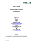
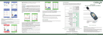
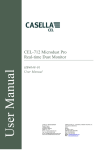
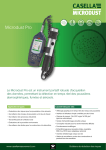
1
“DUST DETECTIVE”
Static Air Sampling Enclosure
For CEL-712 Microdust Pro
User Manual
HB3341-05
CASELLA
Regent House
Wolseley Road
Kempston
Bedford
MK42 7JY
Tel: 00 44 1234 847799
Email: [email protected]
www.casellasolutions.com
COPYRIGHT
The copyright in this document which contains Proprietary information is vested in CASELLA. The contents
of this document must not be used for purposes other than for which it has been supplied or reproduced or
disclosed wholly or in part without the prior written permission of the author.
Rev 5 – 17/07/14
1
TABLE OF CONTENTS
WARNINGS! ................................................................................................................... 3
DUST DETECTIVE - STATIC AIR SAMPLING ENCLOSURE UNIT .............................. 3
Introduction.......................................................................................................................... 3
System Overview ................................................................................................................. 4
Power Supply ....................................................................................................................... 4
USING THE DUST DETECTIVE UNIT ............................................................................ 5
Installation............................................................................................................................ 5
PUF Filter Adaptor ............................................................................................................... 5
Storage of PUF Filters ......................................................................................................... 5
Inserting / Removing PUF Filters ....................................................................................... 5
Collection Filter Cassette ................................................................................................... 5
Powering up and using the system ................................................................................... 6
Checking the Instrument’s Zero ........................................................................................ 6
Checking Probe Span ......................................................................................................... 6
Sampling Pump ................................................................................................................... 6
Starting a Sample Run ........................................................................................................ 6
SERVICE ........................................................................................................................ 7
Enclosure Specification ...................................................................................................... 8
TUFF Pump Specification ................................................................................................... 8
PUF SPARES ................................................................................................................. 8
ORDERING INFORMATION ........................................................................................... 8
Figure 1 - Components and controls for dust detective.
Figure 2 - External view of Dust Detective.
Figure 3 - PUF Filter configurations.
Figure 4 - Adaptor and Filter configurations.
Rev 5 – 17/07/14
9
9
10
10
2
WARNINGS!
The Microdust Pro and associated Static Sampling Unit is non-intrinsically
safe and MUST NOT be used within a hazardous area.
DISPOSAL OF BATTERIES: Batteries and battery packs must never be
disposed of by placing in a fire or incinerator, nor must they be punctured,
crushed or otherwise mutilated or opened up in any way. Disposal must be
in accordance to local environmental legislation.
Ensure the TUFF and Microdust Pro are held firmly by the Velcro straps
provided, otherwise damage to the instruments could occur.
All optical measurement systems are sensitive to the presence of moisture
droplets both in the air and bonded to particulate matter. To prevent
possible measurement errors, the system should not be used in conditions
of high humidity, rainfall or condensation.
The purge valve must be fully removed during operation. Failure to remove
will result in pump shutdown errors.
Dust Detective - Static Air Sampling Enclosure Unit
Introduction
With increased awareness of environmental pollution from fine particulate in the workplace and
increasing enforcement of COSHH and environmental legislation, the demand for more area and
perimeter monitoring on a short to medium term basis is on the increase. This need for real-time
particulate information is a requirement in general industry, when looking at Total Suspended
Particulate (TSP), and at inhalable and respirable dust levels as a health issue.
CASELLA has introduced the “Dust Detective” Static Air Sampling enclosure for exactly this
application. This accessory Provides a simple solution to short to medium term fixed area
monitoring with the Microdust Pro and TUFF sampling pumps and is designed specifically for use
in indoor applications, but some short term outdoor perimeter samples can be undertaken with
the unit.
The IP65 case is designed to accommodate a standard Microdust Pro as well as a TUFF air
sampling pump which Provides a precise inlet flow rate.
The Dust Detective has been designed as an accessory for existing Microdust Pro users as well
as for potential customers looking for a complete system when supplied complete as the Dust
Detective.
(In this format, the enclosure also doubles as the equipment carry case for the Microdust Pro.)
Rev 5 – 17/07/14
3
The complete system would require the purchase of the static air sampling enclosure (Part
number 206105D), plus the following additional items:Microdust Pro,
TUFF air sampling pump
TUFF starter kit or suitable Flow Meter Kit
Pre weighed GFA filters.
The key component to this accessory is the sampling inlet which utilises PUF size-selective filter
techniques. Size-selective filters were originally developed for operation in the Conical Inhalable
Sampler (CIS) as detailed within the Health and Safety Executive publication MDHS 14/4. The
foam filter specifications and dimensions determine the desired aerosol size selection
characteristics and eliminate particle sizes greater than PM10, PM2.5 or Respirable (4 um) as
appropriate. The larger particles become trapped and collect within the foam matrix, whilst all
particles below these “cut-off points” pass through the PUF filters and enter the measurement
chamber, where the real time mass concentration is established.
After passing through the Microdust Pro, particulate matter is deposited on a 37mm filter which
may be used for gravimetric or chemical analysis.
Remember however, although the Dust Detective system has been designed to monitor
particulate fraction concentrations in a variety of environments, it does have some operating
limitations. The instrument is not designed to operate continuously out of doors for long periods
over 13 hours.
Due to the light scattering principle used within the instrument, any moisture which individual
particles attract at periods of high humidity or temperatures aproaching “dewpoint” will be “seen”
by the instrument as larger particles. This biases results towards greater concentrations. Also,
during these periods, any air being drawn through the instrument which is high in humidity may
condense on the optics and distort the light beam, Producing spurious results.
System Overview
The internal configuration of the Dust Detective is shown in Figure 1. The system incorporates an
TUFF sampling pump to draw the sample air through the inlet pipe at a user selected flow rate.
PUF filters are designed to operate at a flow rate upto 3.5 L/min. The inlet head is designed to
prevent the ingress of insects and other large foreign objects. A dust cap is Provided to seal the
inlet port on the case lid whenever the inlet tube is removed for transit purposes.
Size selection of the sample stream is performed by passing the sample through a PUF foam
filter appropriate to the chosen sampling strategy, (PM 10, PM2.5 or Respirable). PUF filter adaptors
are described in Figures 3 and 4. A nozzle on the mounting block is a push fit into the inlet fitting
on the case lid.
Power Supply
The Microdust Pro is powered via internal AA sized dry cells. (This allows the unit to run for
typically 13 hours.)
The TUFF pumps are powered by internal rechargeable cells.
Rev 5 – 17/07/14
4
Using the Dust Detective Unit
Installation
Cutouts are Provided in the foam for the Microdust Pro and TUFF sampling units. Ensure both
units are fully charged up or have new AA cells if required before insertion.
Note: Ensure the TUFF and Microdust Pro are held firmly by the Velcro straps provided;
otherwise damage to the instruments could occur.
Important! The enclosure is fitted with purge valve which must be removed during
operation (see Figure 1). Failure to remove will result in pump shutdown errors.
Connect the TUFF pump to the sampling spigot (X).
Connect the Microdust Probe into the Adaptor Block and correctly align such that the locating
spigot on the PUF Filter Holder locks into the Probe Measuring Chamber. When locked correctly
into position, the complete assembly is prevented from rotating or moving laterally on the Probe.
(see figure 4). The body of the Probe will be located into the retaining clip.
PUF Filter Adaptor
For size-selective monitoring applications, it is necessary to load the apPropriate foam filter(s)
into the inlet adapter. If TSP (Total Suspended Particulate) monitoring is required, then no foams
should be fitted within the inlet assembly and the pump run at 3.5L/min.
The type of foam filter loaded into the adapter determines the size of particulate matter being
monitored by the Microdust Pro and collected on the filter. Although the PUF foam inserts have
been designed as size-selective filters to capture particles larger than a specified mean
aerodynamic size, it is also possible to weigh the PUF inserts before and after measurement to
establish both the total suspended particulate (TSP) value and the desired size fraction.
Storage of PUF Filters
The PUF filters should be kept in a clean and preferably air-conditioned environment.
Inserting / Removing PUF Filters
The PUF filters should be carefully inserted or removed from their respective cassettes using
clean tweezers and plastic gloves. Avoid subjecting the filters to physical damage, creasing or
folding.
Filters should be loaded into the relevant housing as shown in Figure 3,4.
Collection Filter Cassette
A Filter Cassette a 37mm filter. The desired filter type (typically of the GFA type) should be
conditioned and pre-weighed (if required) before being loaded into the cassette. Always handle
filters with care to prevent contamination or physical damage.
Rev 5 – 17/07/14
5
Powering up and using the system
Checking the Instrument’s Zero
Check the zero calibration for the Microdust Pro before every use. This can be achieved either as
described in the Microdust Pro handbook, utilising the purge air bellows connected to the Probe
purge points. Alternatively to calibrate in situ, remove the inlet cowl, and connect the in-line air
filter to the inlet tube, start the TUFF pump. With clean air in the Probe, the display should be
zeroed.
Checking Probe Span
The span of the Microdust Pro should be checked in accordance with the relevant User Manual.
The span can also be checked by inserting the calibration filter and checking the reading. If
required, adjust the span control according to the User Manual.
Sampling Pump
The Dust Detective enclosure is designed to use the TUFF range of personal samplers. This
allows the user to take a standard personal sampling pump, charge the unit up and install inside
the enclosure. The pumps are designed to provide a flow rate capability of up to 4.5 L/min whilst
using a 37 mm GFA filter head. Automatic flow control circuitry is used to maintain a stable
sample flow rate over varying pressure drop conditions.
To switch the pump on, press the enter key on the pump. When running a real time flow meter
symbol will appear on the display and a green flashing light will be visible at the top of the pump.
To switch the pump off, press and hold the enter key and the pump will countdown to off.
PUF filters are designed to operate at a flow rate of 3.5 L/min.
Check the performance and calibrate the TUFF sampling pump according to the manual and
adjust the flow rate to 3.5 L/min.
If the pump is unable to maintain the selected flow rate due to excessive pressure drop or an inlet
blockage, the red LED will begin to flash and the warning tone will bleep rapidly.
Starting a Sample Run
1.
2.
3.
4.
5.
Remove the Protective dust cap and fit the sample inlet tube/head to the case (see
fig 2).
Insert the PUF filter foam(s) and in line sample filter (if required) (see figure 3, 4).
Switch the Microdust Pro and TUFF pump on. Confirm zero using the in-line filter
connected to the sample inlet.
Check that the TUFF flow rate is set to 3.5L/min.
Locate unit in required location. Start pump and Microdust data logger according to
their respective user manuals.
Rev 5 – 17/07/14
6
SERVICE
It is recommended that the unit is serviced annually, more frequently when used in areas of high
dust concentrations.
CASELLA’s in house service department offers a comprehensive range of repair and calibration
services, designed to effect a fast and efficient back-up for all our Products. The service
department is operated under the scope of our BSI registration for Products manufactured by us.
We will however, undertake the repair of other manufacturers’ equipment.
For further information please contact CASELLA’s Service Department at our Bedford premises.
We will be happy to Provide quotations for individual repairs or provide annual maintenance
under contract.
We recommend factory service by technicians trained and equipped to repair your
instrumentation.
Should you wish factory repair/calibration please complete a ‘Returns Material Authorisation’
online form http://rma.casellameasurement.com/ to obtain an RMA number.
Send your equipment in suitable transit packaging, insured to full value and ship pre-paid. Please
quote the RMA number with any accompanying paperwork which will help us to identify the
correct number of items and what needs to be done.
Send to:
CASELLA Service Department
Regent House
Wolseley Road
Kempston
Bedford
MK42 7JY
If purchased outside the United Kingdom, please return to your distributor.
Rev 5 – 17/07/14
7
TECHNICAL INFORMATION
Enclosure Specification
Operating temperature range:
Storage temperature range:
Humidity range:
Storage humidity range:
Size:
o
+5 to +40 C in the absence of condensation
o
-25 to +55 C
30 to 90% RH Provided there is no condensation
0 to 90% RH in the absence of condensation
410 x 330 x 175 mm
TUFF Pump Specification
Flow range
Flow control accuracy
Operating temperature
.
0.8 to 4.5 L/min
±5% for selected flow
o
0 to +45 C
PUF Spares
Foam filter - PM2.5 (pk of 10)
Foam filter - PM10 (pk of 10)
Foam filter - Respirable (pk of 10)
P118204
P118206
P118208
Ordering Information
Static Air Sampling Enclosure
Microdust Pro Kit
TUFF 4 I.S. Sampling pump with charger
Rev 5 – 17/07/14
206105D
CEL-712/K1
P314221
8
Accessories
in pouch
Filter cassette
and adaptor
Probe
Inlet Head
TUFF pump
Calibration insert
Spare batteries
PM2.5
adaptor
CEL-712
Microdust
Pro
Purge valve – Remove
during operation!
Figure 1 - Components for dust detective.
Figure 2 - External view of
Dust Detective.
Rev 5 – 17/07/14
9
Figure 3 - PUF Filter configurations.
Pump connection
Dia. 37mm filter
holder
Measuring
chamber
O-Ring
O-Ring
Locating spigot
Microdust probe
Adaptor
Alternatives
PUF filter holder
PM10 / Respirable
(optional)
} {
Locating spigot
PUF filter holder PM2.5
PUF filter head cap
Figure 4 - Adaptor and Filter configurations.
ALTERATION WITHOUT NOTICE
The contents of this manual are subject to change without notice
Rev 5 – 17/07/14
10